1. Introduction
Nowadays, it is common to investigate the effects of various process parameters on the properties of molded parts prepared using Inconel 738 laser direct deposition molding. However, the properties of the molded parts are more affected by changes in the morphology of individual passes and layers. The influence of inclusions between passes on the properties of the molded parts is even more significant under different combinations of process parameters. Currently, there are very few studies of this nature. Inconel 738 exhibits an excellent high-temperature strength, toughness, hardness, and resistance to heat corrosion, making it a popular choice for various applications, such as ships, industrial gas turbines, nuclear reactors, and petrochemicals. It is also used in high-end components, such as aeroengines and supersonic airplanes [
1,
2]. However, Inconel 738 faces problems with weldability and susceptibility to hot cracking, which significantly impact its machinability and the performance of its components. At present, the inclusion cracking issue of Inconel 738 alloy can be addressed through three main approaches: optimizing the powder composition, optimizing the process parameters of laser additive manufacturing, and incorporating physical field technology. It has attracted great attention in various fields, and related research work has been carried out [
3,
4,
5]. Compared to other popular alloys, such as Inconel 718, Inconel 600, Monel 400, and Ti6Al4V, Inconel 738 holds a greater economic and industrial significance. Driven by the increasing demand in recent years, the market size of nickel-based alloys has grown significantly. It is projected that the market value in 2020 will reach approximately CNY 11.096 billion. In the field of aerospace engines, the use of nickel-based alloy materials comprises from 40% to 60% of the total, with a market value of CNY 6.203 billion. In the field of nuclear power, the market is worth CNY 1.979 billion. In recent years, China has experienced a steady growth in the production of nickel-based alloys. In 2020, the output of nickel-based alloys reached approximately 27,600 metric tons, with a sales volume of about 50,900 metric tons. Among them, the use of Inconel 738 has surpassed one-third of the total utilization of nickel-based alloys. With the continuous growth of the downstream nickel-based alloy industry, the industry scale is also projected to expand in the future. It is expected that the industry value will reach CNY 55.034 billion by 2027.
Laser additive manufacturing (LAM) can create a three-dimensional model of the metal parts by using professional software to slice and layer the data, resulting in a two-dimensional deposition path. Through the use of digital technology, a high-energy laser beam will be employed to achieve the direct formation of three-dimensional parts with a high degree of freedom. This will be accomplished by melting and depositing the material point by point, line by line, and surface by surface [
6,
7]. Direct laser deposition (DLD) is based on the principle of discrete/stacking by layering the 3D CAD model of the part, obtaining the 2D contour information of each layer’s cross-section, and generating the machining path. In an inert gas-protected environment, high-energy-density lasers are used as the heat source to melt and stack powders or wires layer by layer along a predetermined machining path. This process enables the direct manufacturing and repair of metal parts. The most effective approach to address the issues of poor forming and cracking in the manufacturing of Inconel 738 using direct laser deposition technology is to optimize the parameters of the forming process. The change in process parameters will directly affect the deposition geometry, microstructure, residual stress, and mechanical properties. Therefore, it is necessary to conduct relevant studies on the process parameters in order to obtain dense and high-performance depositions [
8]. The selection of process parameters, such as the laser power, scanning speed, and powder feeding rate, plays a crucial role in the quality of the mold [
9]. The deposition gradually transitions from a single to multiple coats, and the quality of the single coat directly affects the overall quality [
10,
11]. Quality assessment requires a defect-free surface, without cracks, with appropriate values for the height, width, height-to-width ratio, and wetting angle size. In recent years, numerous scholars have developed models and empirical formulas to examine the impact of process parameters and their combinations on deposition morphology and properties. This has been achieved through the use of response surface analysis and linear regression analysis [
12]. Perevoshchikova et al. [
13] achieved a microcrack-free and macroscopic porosity of only 0.5% in molded samples by using a low-energy laser, setting a medium scanning speed, and employing a small scanning pitch. The interaction among scanning speed, laser power, and scanning spacing greatly influences the formation of microcracks and pores. Mondal et al. utilized the width and depth of the deposition as indicators to investigate the impact of each process parameter on deposition. This was achieved through the implementation of an orthogonal experimental design, an artificial neural network, and analysis of variance [
14]. Barekat et al. investigated the relationship between the laser power, scanning speed, powder feed rate, and the geometrical characteristics of single-layer, single-pass depositions. They conducted a linear regression analysis and designed a guide for selecting the process parameters to achieve the desired deposition characteristics [
15]. Ansari [
16] proposed the use of a regression model to predict the deposition morphology. This was achieved by analyzing the effect of laser additive manufacturing parameters on the deposition morphology using nickel-based alloy powder. T. Muthuramalingam [
17] utilized the Taguchi–Grey correlation method to examine the impact of process parameters on surface property measurements while machining titanium alloys. It was found that the laser power (3 kW), nozzle distance (1.5 mm), focal length (−2 mm), and gas pressure (2 bar) were determined to be the optimal combinations of process parameters, resulting in less plasma energy and an accuracy of 2.2%. Ammar H. Elsheikh [
18] conducted statistical analysis to examine the impact of various laser cutting parameters on the kerf characteristics. The results showed that increasing in cutting parameters leads to an increase in the top and bottom width of the saw kerf, while increasing in cutting speed or laser power leads to an increase in the taper of the kerf. Ahmed B. Khoshaim [
19] utilized the Taguchi L18 hybrid design to investigate the impact of four process parameters (laser power, cutting speed, auxiliary gas pressure, and plate thickness) on five process responses: the kerf deviation, top heat-affected zone, bottom heat-affected zone, maximum surface roughness, and roughness area. The results show that as the laser power increases, the cutting speed decreases, the surface roughness worsens, and the heat-affected zone widens. Ammar H. Elsheikh [
20] proposed a solution to address the margin problem in order to accurately calculate the transient temperature field during laser heating. The experiments were conducted using a continuous-wave CO
2 laser with a maximum power of 150 W to validate the findings. Ammar H. Elsheikh [
21] utilized the Taguchi L18 orthogonal array design to examine the impact of four input variables—gas pressure, sheet thickness, laser power, and cutting speed—on five kerf quality metrics: the rough zone ratio, upper and lower heat-affected zone width, maximum surface roughness, and kerf taper angle. The results show that the RVFLEO model has a strong ability to accurately predict the laser-cutting characteristics of PMMA sheets.
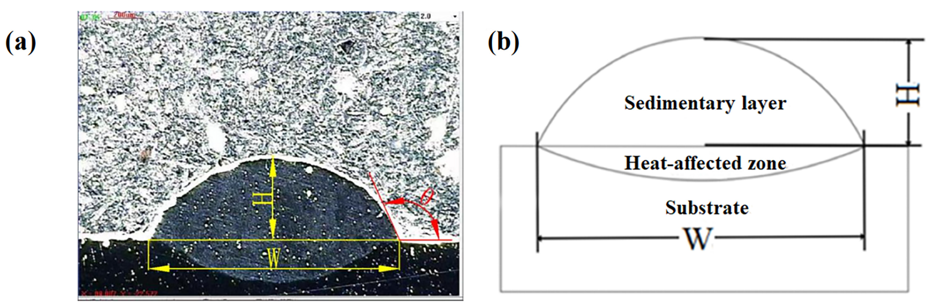
In this paper, a multi-factorial and multi-level experimental design was adopted to investigate the effects of changes in the process parameters on the morphology of the deposited layer and the inclusions between channels. This was achieved through one-way analysis, extreme analysis, and analysis of variance (ANOVA) using three process parameters: the laser power, scanning speed, and powder feeding rate, as the influencing factors. The responses measured were the wetting angle, height, width, and their ratios. The goal was to determine the optimal values of the process parameters that would result in the lowest number of inclusions in the multi-channel deposited layer. The optimal value for each process parameter is obtained when there is a minimum of multi-channel sedimentary layer inclusions. At the same time, a mathematical model was developed to characterize the relationship between the geometrical parameters of the cross-section and the surface tension and gravity. This was conducted in conjunction with the theoretical derivation of the spherical crown model.
3. Experimental Results and Analysis
Based on the multi-factorial and multi-level experimental design, five levels of laser power, four levels of scanning speed, and three levels of powder feeding rate were selected. The width of the deposited layer W, the height H, the aspect ratio H/W, and the wetting angle θ were used as the four response variables.
As shown in
Figure 3 and
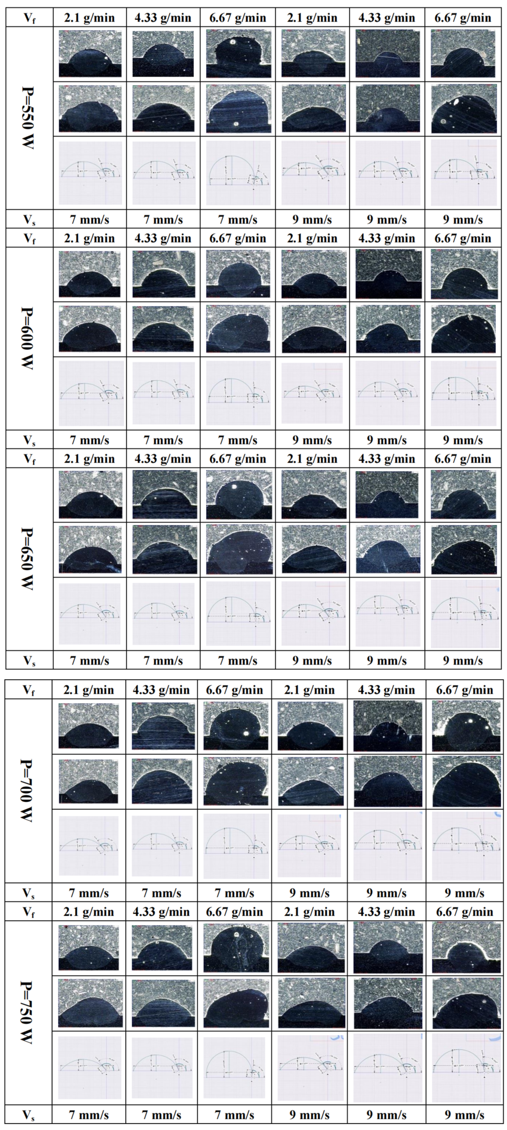
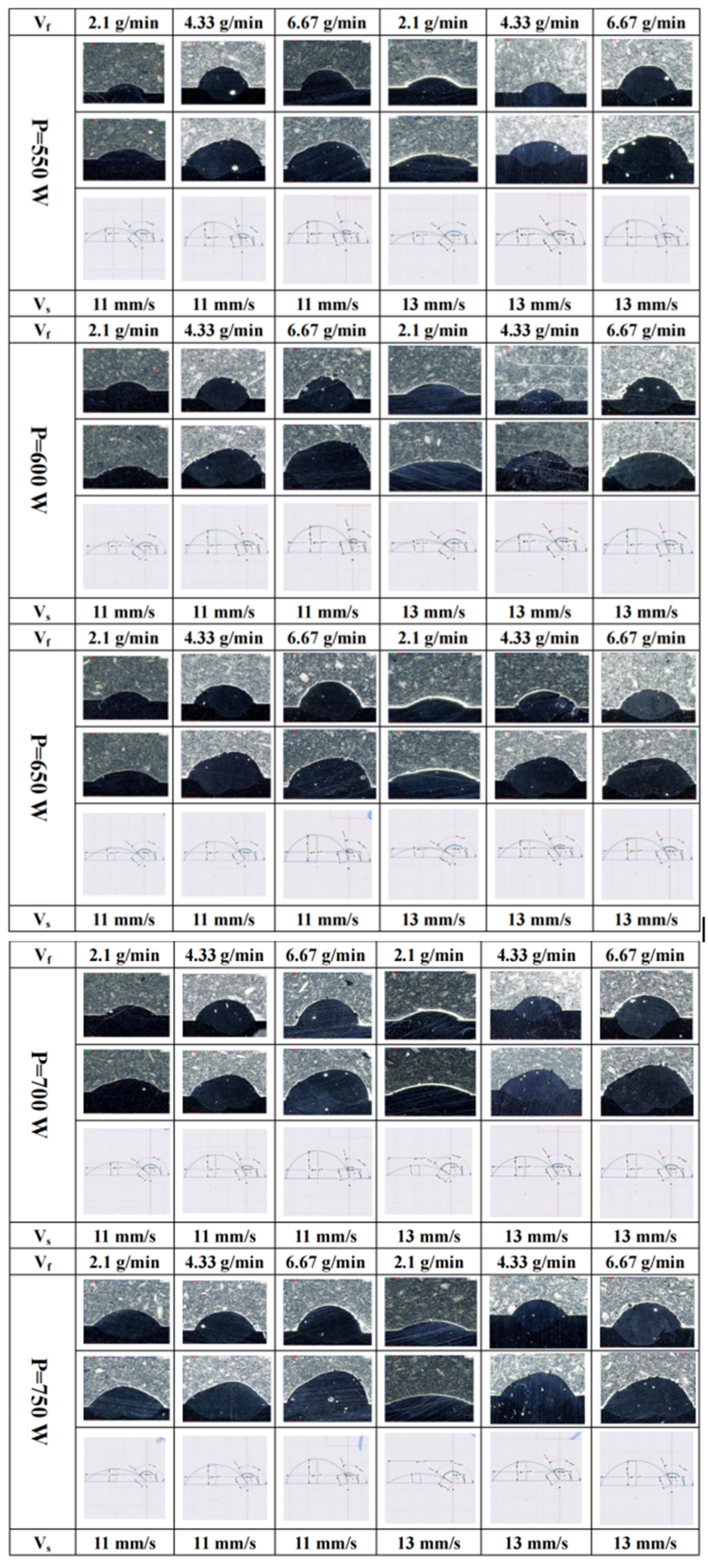
Figure 4, 60 sets of single-layer, single-pass, single-layer multi-pass, and single-layer, single-pass theoretical cross-sections are demonstrated at laser powers of 550 W, 600 W, 650 W, 700 W, and 750 W; scanning speeds of 7 mm/s, 9 mm/s, 11 mm/s, and 13 mm/s; and powder feeding rates of 2.1 g/min, 4.33 g/min, and 6.67 g/min. The single-layer, single-pass theoretical cross-sections were drawn using Shapr3D software (Version number: 3.46.1).
Table 2 displays the 60 groups of single-layer, single-pass physical cross-sections, along with the corresponding height and width measurements obtained using the optical imager. By using Shapr3D software, the height and width of each physical cross-section were sequentially defined. This allows the creation of a theoretical single-layer, single-channel cross-section. In this case, each group of process parameter combination experiments was repeated three times, which ensures the sufficient reproducibility and high accuracy of the obtained data.
3.1. One-Way Analysis of Variance
- (1)
The widths of the depositions
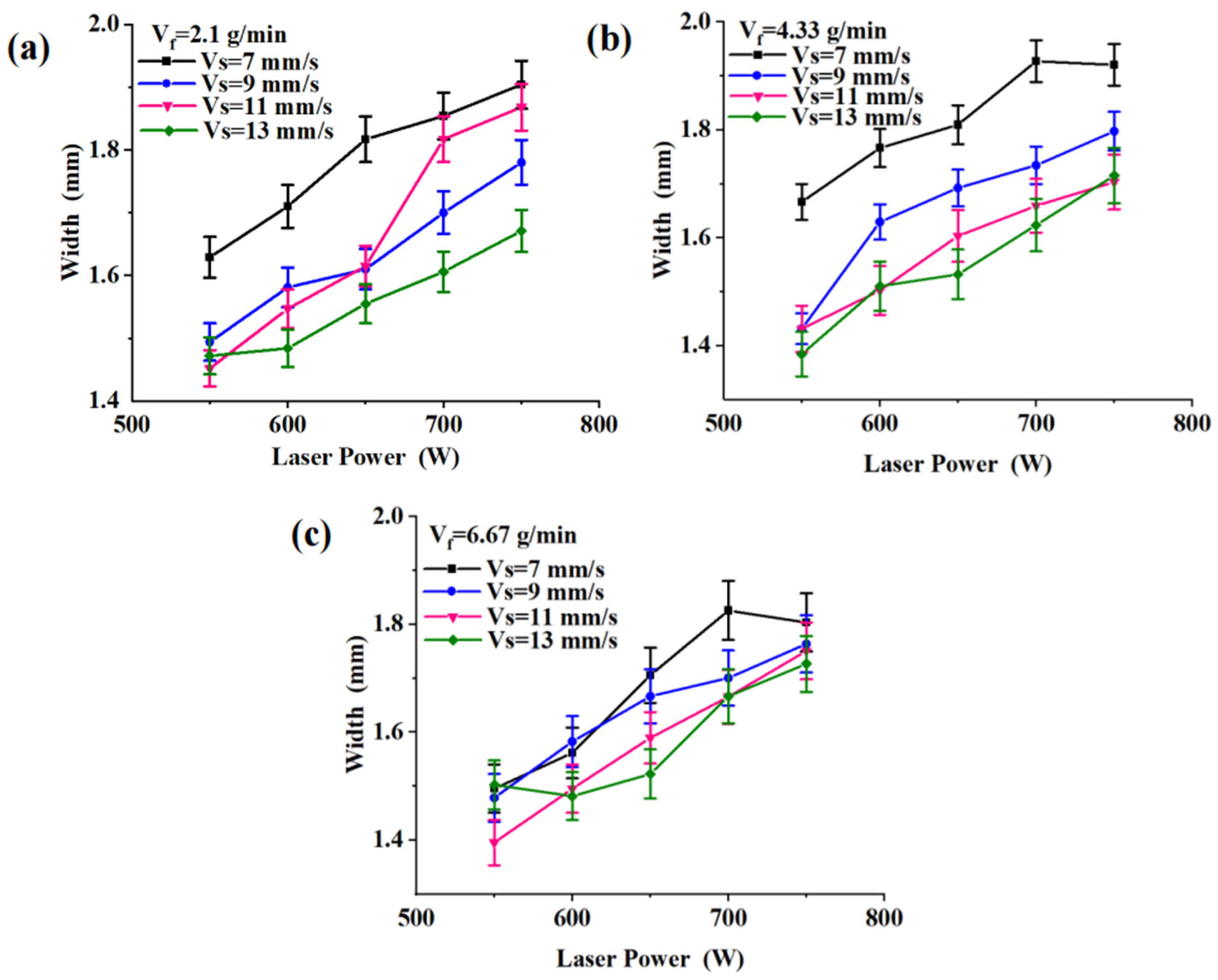
We used Origin 2018 to plot the trend curve for the width of the layer deposited via laser power. As shown in
Figure 5, the width of the deposited layer exhibits an increasing trend with the rise in laser power, assuming all the other conditions remain constant. This is because as the laser power increases, it primarily impacts two factors. Firstly, the energy input to the substrate’s surface increases, leading to an expansion in the size of the molten pool. Consequently, the width of the molten pool also increases. Secondly, the quantity of laser-melted metal powder increases, resulting in a larger amount of material involved in the formation of the deposited layer. This, in turn, contributes to a wider width. The scanning speed has a negative effect on width, and increasing the scanning speed will, to some extent, cause the width to decrease. This is because a scanning speed that is too fast reduces the amount of linear energy input per unit length.
- (2)
The heights of the depositions:
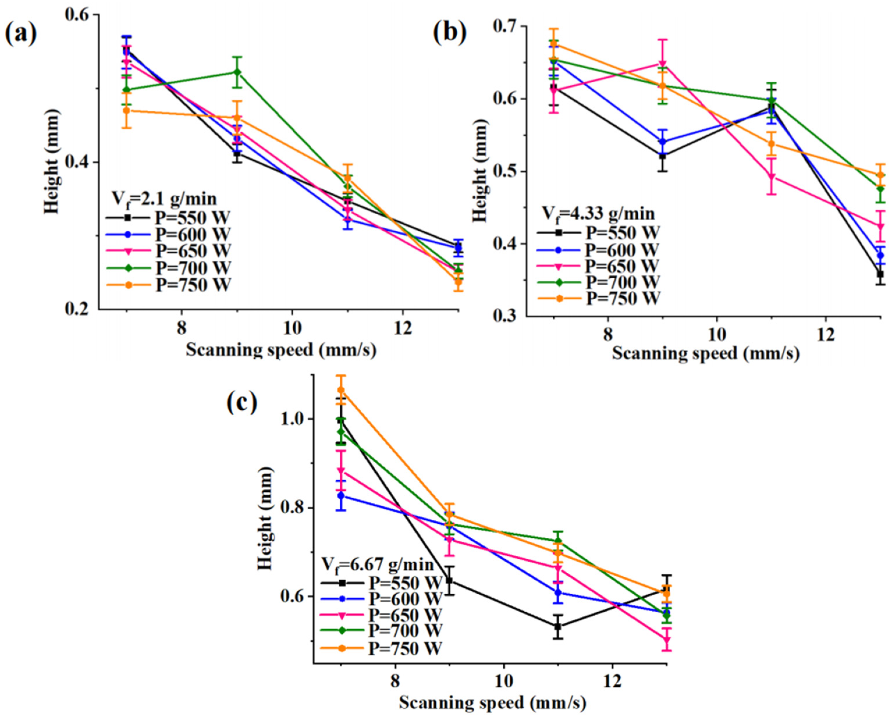
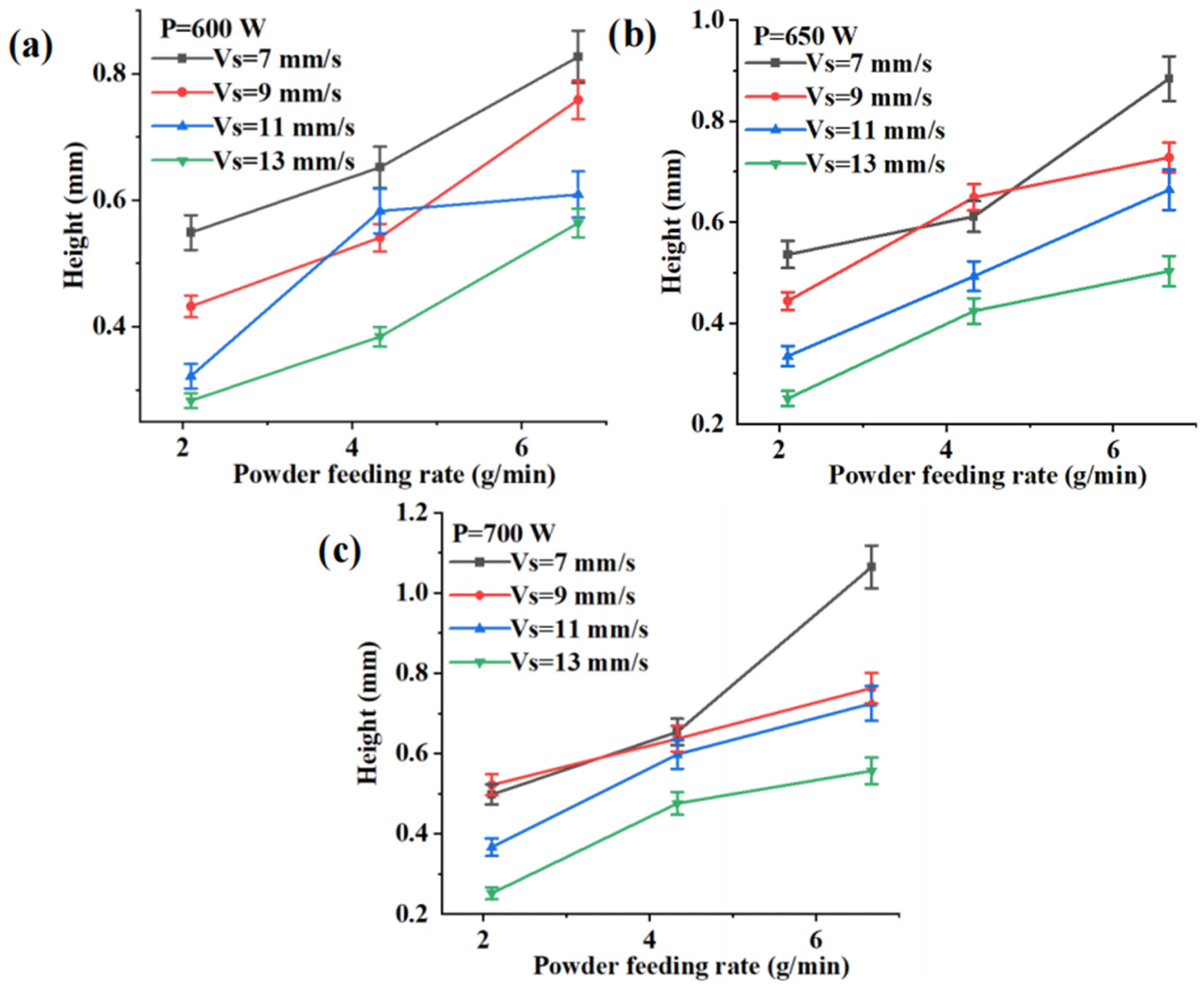
As can be seen in
Figure 6 and
Figure 7, the height of the deposited layer decreases with an increase in the scanning speed and increases with an increase in the powder delivery rate, while keeping the other parameters constant. The reason for this phenomenon can be explained as follows: The increase in scanning speed causes the laser to spend less time at a specific position on the substrate. This leads to a decrease in the amount of energy applied per unit length, resulting in a reduction of melted metal powder and a smaller or shallower molten pool. Secondly, under the premise of maintaining a constant powder feeding rate, increasing the scanning speed will result in a decrease in the mass flow rate per unit length of the powder. The increase in the powder feed rate results in a higher amount of powder that can be melted by the laser per unit of time. This, in turn, leads to a greater amount of powder being involved in the formation of the deposition layer, resulting in an increase in height.
- (3)
The wetting angles of the depositions:
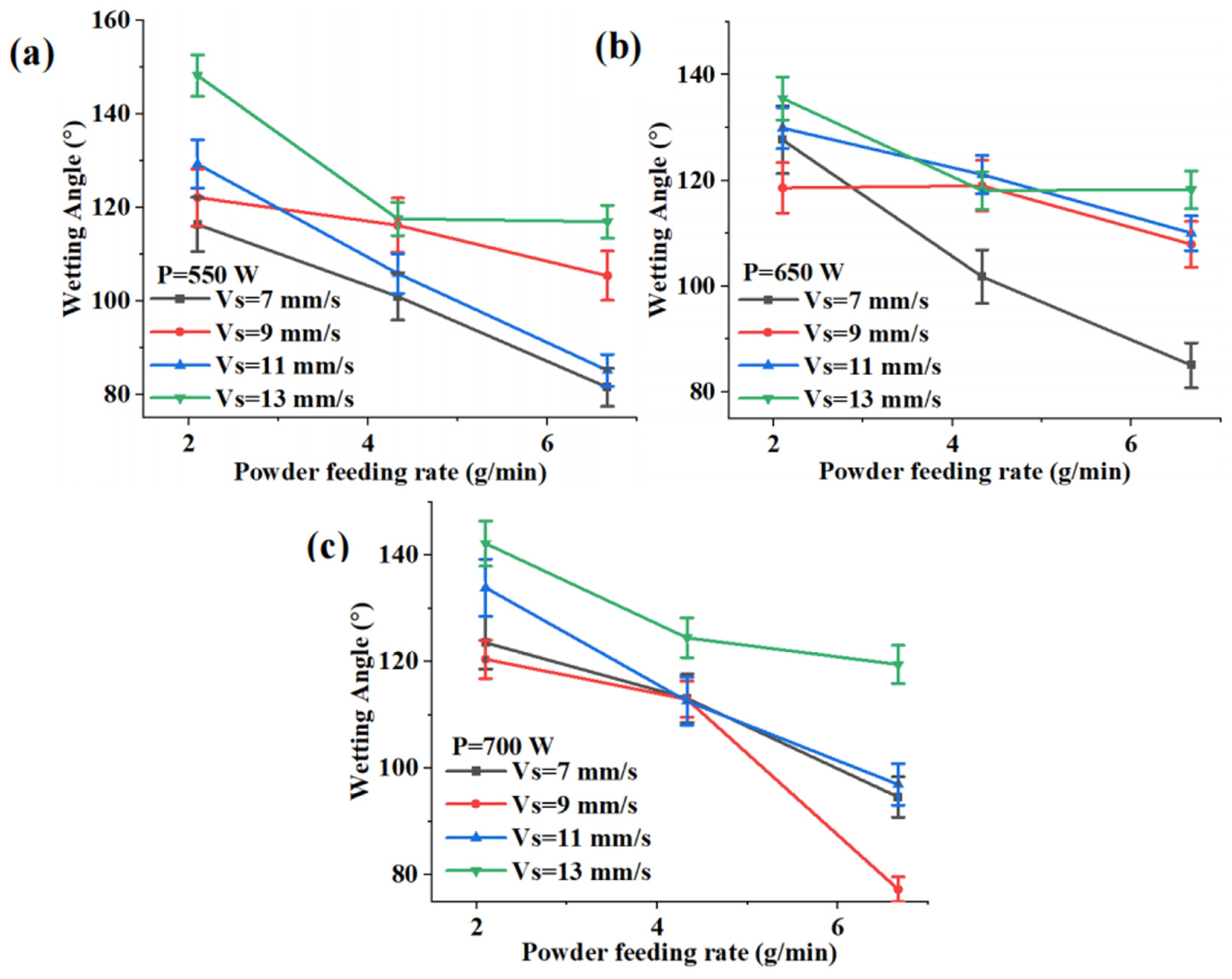
From
Figure 8, it can be observed that the wetting angle gradually decreases as the powder feeding rate increases, while keeping the laser power and scanning speed constant. This can be attributed to the previous variations in height. From
Figure 7, it can be observed that when other parameters are held constant, an increase in the powder feeding rate leads to a gradual increase in height. Consequently, the wetting angle becomes steeper and smaller. With the increase in scanning speed, the wetting angle gradually becomes larger. This is because the increase in scanning speed leads to a decrease in height, resulting in a larger wetting angle. As shown in the figure, when the laser power is increased to over 650 W, the wetting angle formed at a scanning speed of 7 mm/s is greater than the angle formed at 9 mm/s, while the powder feeding rate remains at 2.1 g/min. This indicates that, under this specific combination of parameters, the excessively high power level leads to a sudden alteration in the formation of the wetting angle.
3.2. Extreme Analysis
Based on the 60 groups of multi-factorial and multi-level experimental data in
Table 4, single-factor analysis was conducted to determine the impact of each group of process parameter combinations on the geometrical shape of the fused deposition layer. Therefore, based on single-factor analysis, it is important to select representative combinations of process parameters for orthogonal experimental extreme analysis. Using the wetting angle as the reference index, the data results were obtained from 23 groups of parameter combinations with a single-pass wetting angle greater than 120°. These results were selected from a total of 60 groups of process parameter combinations. The laser power values of 600 W, 650 W, and 700 W; scanning speeds of 9 mm/s, 11 mm/s, and 13 mm/s; and powder feeding rates of 2.1 g/min, 4.33 g/min, and 6.67 g/min were analyzed using polar analysis and an orthogonal experimental design. The analysis aimed to determine the primary and secondary orders of influence for each factor. An orthogonal experimental design was used for polar analysis to determine the primary and secondary orders of influence of each factor. According to the calculation rule of the orthogonal experiment, the results of the orthogonal experiment with three factors and three levels were calculated and are listed in
Table 4.
In
Table 4, K1, K2, and K3 represent the average values of the three levels of the respective indicators in the columns where the factors are located. R represents the calculated range, and the subscripts W, H, and θ represent the values associated with the width, height, and wetting angle of the fused deposition layer, respectively.
From
Table 4, it can be observed that RW (P) > RW (V
S) > RW (V
f), RH (V
f) > RH (V
S) > RH (P), and Rθ (V
f) > Rθ (V
S) > Rθ (P). This indicates that the deposition width is primarily influenced by the laser power, followed by the scanning speed, and lastly, the powder feeding rate. On the other hand, both the deposition height and the wetting angle are mainly affected by the powder feeding rate, followed by the scanning speed, and finally the laser power.
According to the results of orthogonal experiments, Mini Tab software (The version number: 21) was used to analyze the height of the deposition layer H, width W, aspect ratio H/W, and wetting angle θ as the response indices for data processing. The order of the influence of each factor on the response indices as well as the trend of change were determined using the mean value response table (in which the levels of A, B, and C represent the laser power, scanning speed, and powder feeding rate, respectively). The design is summarized in
Table 5, and the mean response tables for the four responses are shown in
Table 6,
Table 7,
Table 8 and
Table 9.
As can be seen from the mean response tables in
Table 6,
Table 7,
Table 8 and
Table 9, the results obtained from processing the data through Mini Tab are consistent with the experimental results calculated in
Table 4. This indicates that the experimental calculations are reasonable.
From the orthogonal experiments, it can be seen that the deposition inclusions and morphology are determined jointly by various process parameters. Therefore, when selecting process parameters, it is important to consider different parameters for deposition inclusions and the morphology they cause due to their distinct effects. Based on this, ANOVA will be performed to investigate the effect of the interaction between the two factors on the deposition inclusions and morphology.
3.3. ANOVA (Analysis of Variance)
3.3.1. Influence of Process Parameters on Heights of the Depositions
It is important to control the height in order to obtain a homogeneous sediment layer. Therefore, it is important to study the effect of each factor on height and determine the percentage contributed by each factor. ANOVA was used to analyze the effect of the height of the sedimentary layer in relation to each factor, and the results are presented in
Table 10.
From
Table 10, the F value of the model is 19.58, with a
p-value < 0.0001, indicating that the model is statistically significant. The regression model explains 96.62% of the variation in the coating height, as shown by the regression coefficient R-sq in
Table 10. The value of R-sq in this model is also very close to unity, which indicates that the adopted DOE model explains the relationship between height and the other factors well. The
p value for the scanning speed, powder delivery rate, and their interaction is less than 0.05. Therefore, statistically, the scanning speed and powder delivery rate have the most significant impact on height. The
p value for laser power was found to be 0.065, indicating that its impact on height was not statistically significant.
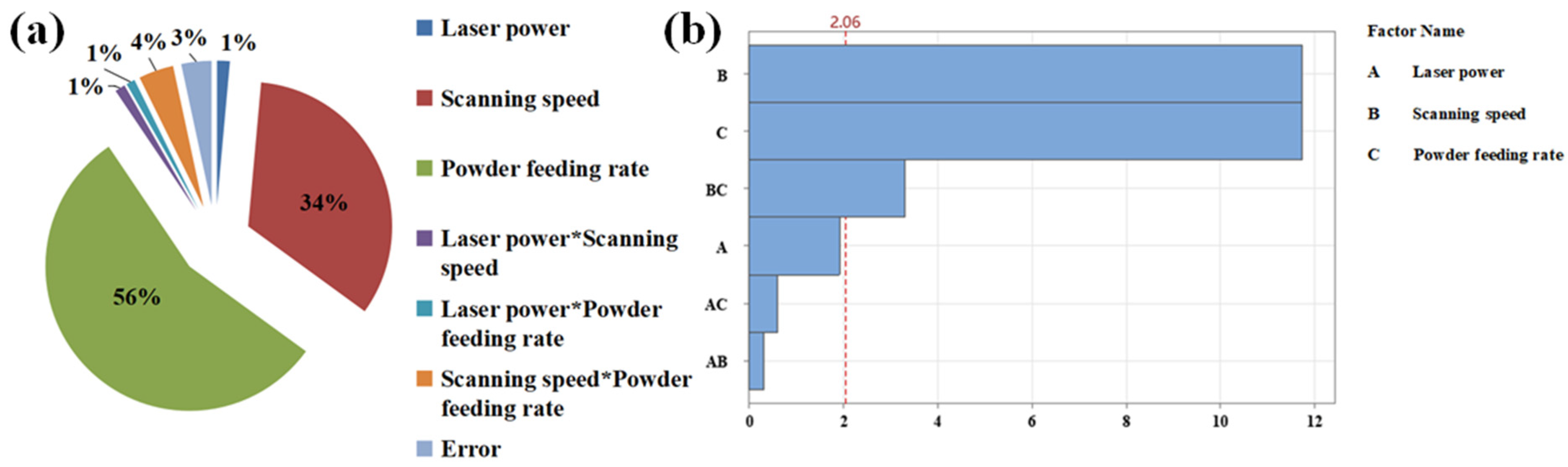
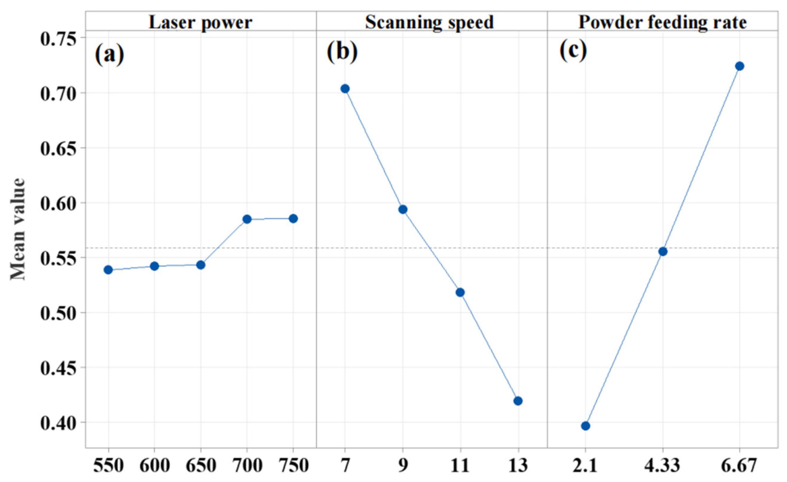
To determine the proportional effect of each factor, pie charts were created using the sum of the squares from the ANOVA table, as depicted in
Figure 9a, and Pareto charts, as illustrated in
Figure 9b.
As shown in
Figure 9a, the powder feeding rate is responsible for 56% of the variation in height, making it the most significant parameter affecting the height. The scanning speed accounts for 34% of the variation, making it the second most important parameter. The laser power, on the other hand, only contributes to 1% of the variation in the height of the deposited layer.
Figure 9b also indicates that the scanning speed, powder feeding rate, and their interaction have the most significant impact on the height, which aligns with the findings presented in
Table 9 and
Figure 9a.
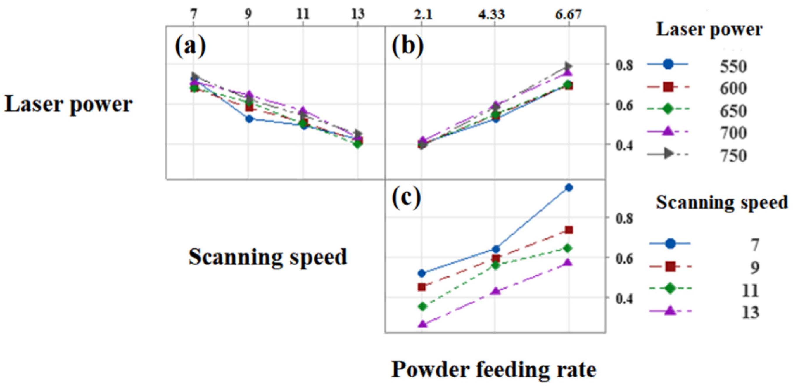
The main effect plots and interaction plots of the main study parameters on height are shown in
Figure 10 and
Figure 11, respectively.
From the main effect plot, it can be observed that the maximum impact on the height of the deposited layer was achieved when the laser power was set at 750 W, the scanning speed was set at 7 mm/s, and the powder feeding rate was maintained at 6.67 g/min. And the effect on the height is much greater than the mean value level when the powder feeding rate is 6.67 g/min, followed by the scanning speed, and finally, the laser power. The change in laser power has no significant effect on the height. In fact, the heights remain almost the same at 550 W, 600 W, 650 W, 700 W, and 750 W. The heights of the layers at 550 W, 600 W, 650 W, 700 W, and 750 W are almost the same. This phenomenon can be explained by the fact that as the laser power increases, the amount of energy input also increases, resulting in a larger melt pool. However, the growth rate of the deposited layer will no longer increase significantly when the powder feed rate is maintained at a constant level. Therefore, it is also necessary to control the domain value of the laser power; otherwise, it will result in some degree of wastage. From the interaction plot, it can be seen that there is no significant interaction between the laser power and scanning speed. This is because the trend of height change is consistent with the increase in scanning speed at various laser powers. Similarly, there is no interaction between laser power and powder feeding rate.
3.3.2. Influence of Process Parameters on Widths of the Depositions
The width of the single-pass deposition layer is an important factor that affects its forming efficiency. As indicated by the regression coefficient R-Sq, the model accurately represents 97.51 percent of the width variance, demonstrating a strong fit. This is evident in
Table 11.
As shown in
Table 11, the model has an F value of 26.85, with a
p value < 0.0001, indicating its statistical significance. Additionally, the R-Sq value is close to unity, suggesting that the DOE model accurately represents the relationship between the widths and each parameter. The standard error of the model was only 0.03, indicating that the model is accurate. The analysis results of the
p values indicate that the laser power, scanning speed, powder feeding rate, and the interaction between scanning speed and powder feeding rate all have statistically significant effects on width, with values less than 0.05. The sum of squares values of the individual factors in the ANOVA table were used to determine the ratio effect of the influencing factors on width. Pie charts illustrating the practical significant factors for width were constructed, as depicted in
Figure 12a, and Pareto charts are shown in
Figure 12b.
As can be seen from
Figure 12a, the laser power affects the width by 60% and is the most significant factor in determining the width. The scanning speed is the second most important factor, accounting for 28%. Among all the factors, only 2% of the variation is caused by the powder feeding rate. The Pareto chart also demonstrates that the laser power, scanning speed, and the interaction of the scanning speed and powder feed rate have the greatest influence on width.
The main effect plots and interaction plots of the main study parameters on width are shown in
Figure 13 and
Figure 14, respectively.
From
Figure 13, it can be seen that the width of the deposited layer is most affected when the laser power is set to 750 W, the scanning speed is 7 mm/s, and the powder feeding rate is 2.1 g/min. The effect on the width is much greater than the mean value when the laser power is 750 W, followed by the scanning speed, and finally, the powder feeding rate. The variation in the powder feed rate does not have a significant impact on the mean width value. Additionally, there is minimal change in the width at powder feed rates of 2.1 g/min, 4.33 g/min, and 6.67 g/min. From the interaction plots, it can be seen that there is no interaction between the laser power and scanning speed, or between the laser power and powder feeding rate. On the contrary, when the scanning speed is 9 mm/s and the powder feeding rate is 11 mm/s, and the powder feeding rate is 2.1 g/min and 4.33 g/min, the response quantity changes differently at different levels of the other parameter. This indicates that there is a clear interaction between these two factors.
3.3.3. Influence of Process Parameters on Wetting Angles of the Depositions
The wetting angle is one of the most crucial parameters for assessing the uniformity of the deposited layer, and a wetting angle of less than 120° results in an inadequate formation.
From
Table 12, the F value of the model is 6.99, with a
p value < 0.0001, indicating that the model is statistically significant. The regression coefficients indicate that the laser power, scanning speed, powder feed rate, and their interaction collectively explain 91.06% of the variation in the wetting angle. The comparison with the mean square of the other parameters yielded a low standard error, indicating that the model is satisfactory. From the
p value results, it is clear that the
p values of the scanning speed and powder feeding rate are both less than 0.05. Therefore, statistically, these two factors have a significant effect on the wetting angle results. The
p value for the laser power and the interaction between two of the three factors is greater than 0.05. Therefore, none of their effects on the wetting angle are statistically significant. The sum of the squares values of the individual factors in the ANOVA table were used to determine the effect ratio of each influencing factor on the wetting angle. Pie charts depicting the practical significant factors were constructed, as shown in
Figure 15a, and Pareto charts are shown in
Figure 15b.
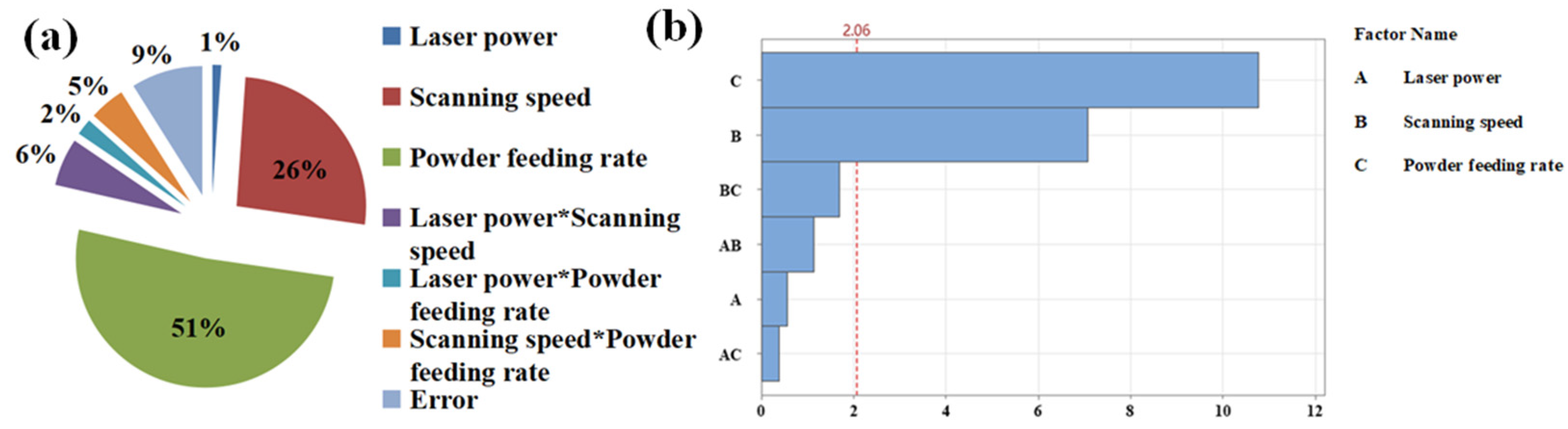
From
Figure 15a, it can be seen that the powder feeding rate has a significant effect on the wetting angle, accounting for 51% of the variation in the wetting angle. This indicates that the powder feeding rate is the most influential factor in determining the wetting angle. The scanning speed is the second most important factor, accounting for 26%. Of all the factors, only 1% of the variation is attributed to the laser power. The Pareto chart also demonstrates that the powder feeding rate and scanning speed are the most influential factors affecting the wetting angle.
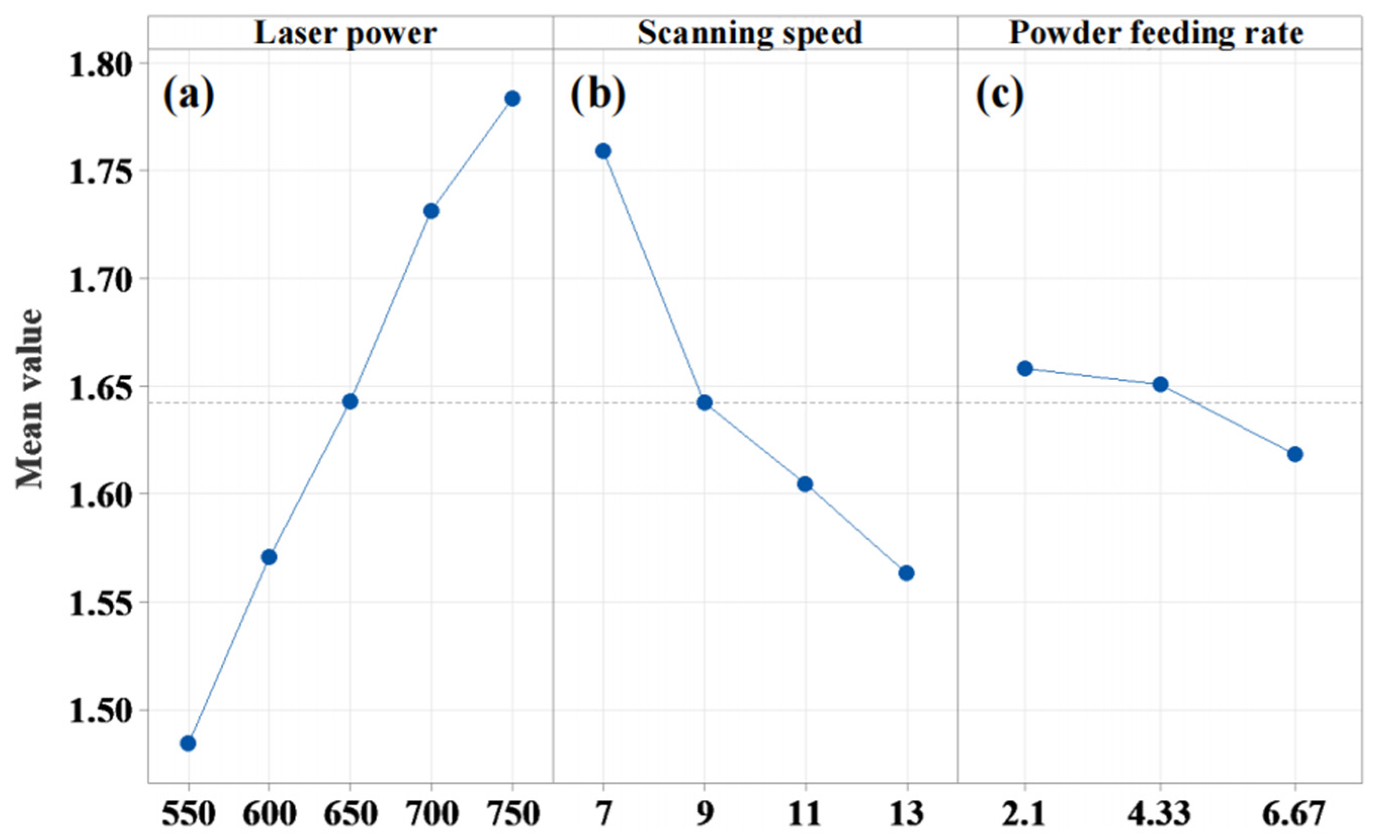
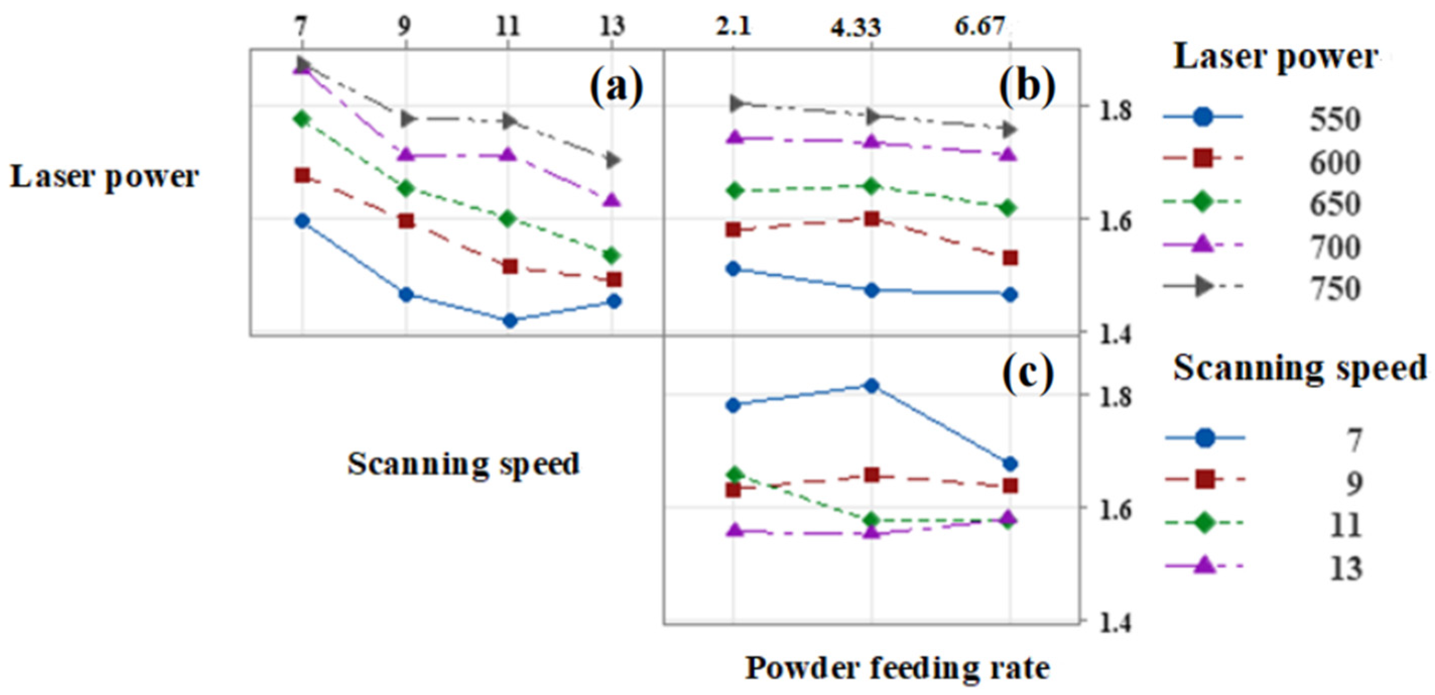
The main effect plots and interaction plots of the studied parameters on the wetting angle are shown in
Figure 16 and
Figure 17, respectively.
As shown in
Figure 16, the wetting angle of the deposited layer is most affected when the laser power is 600 W, the scanning speed is 13 mm/s, and the powder feeding rate is 2.1 g/min. The effect on the wetting angle is significantly greater than the mean value when the powder feeding rate is 2.1 g/min, followed by the scanning speed, and finally, the laser power. The change in laser power does not have a significant effect on the mean value of the wetting angle, and there is almost no noticeable change in the wetting angle from 550 W to 750 W. However, the impact of laser power on the wetting angle is still considerable. From the interaction plot, it can be seen that there is no significant effect of two-by-two interactions among the three factors. Additionally, with different parameter values, the wetting angle shows a consistent change trend.
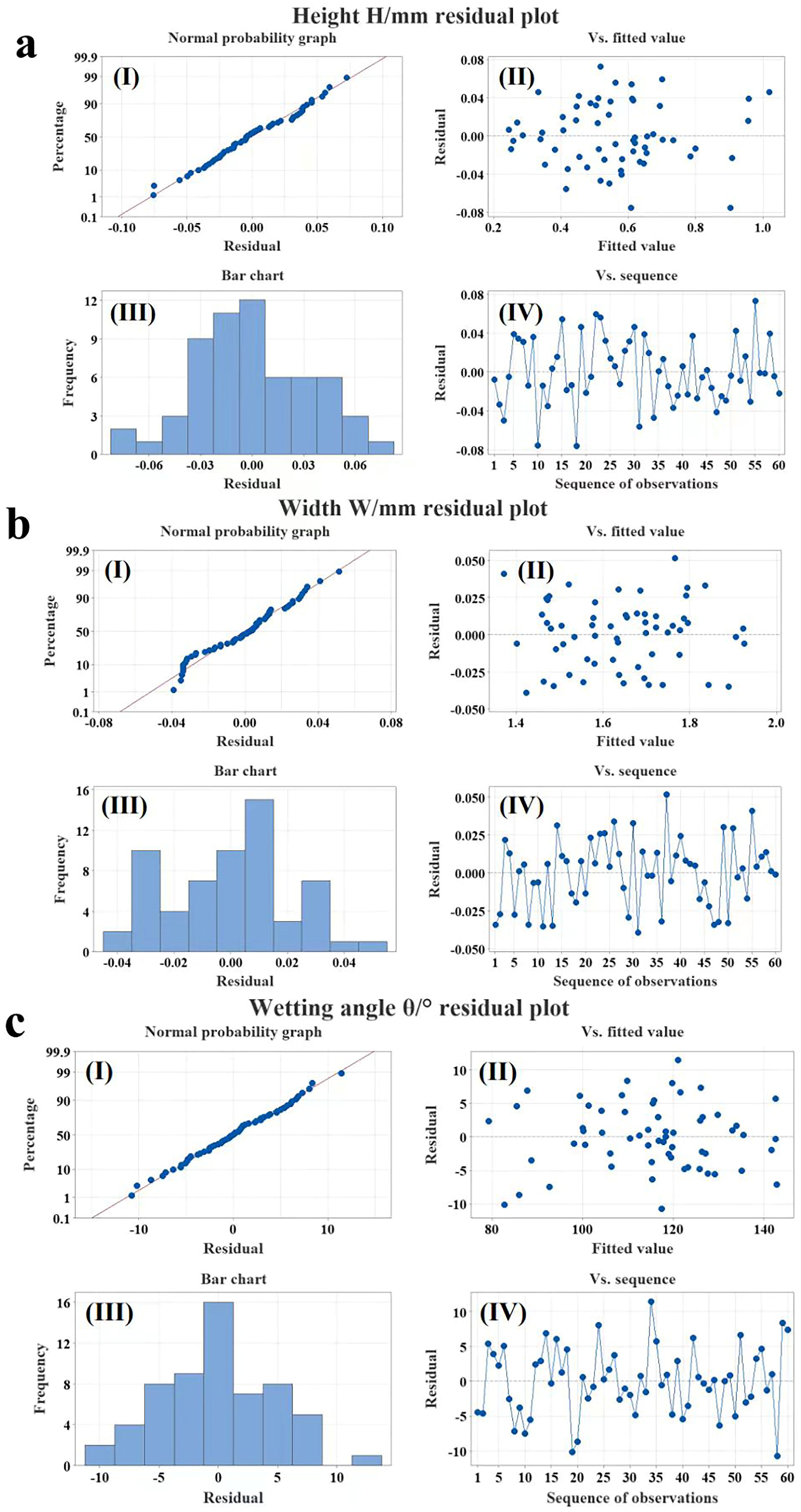
The results of the residual plots for the height, width, and wetting angle of the sedimentary layer are presented alongside the analysis of variance (ANOVA) results. Additionally, pie charts depicting the significant influences, Pareto charts, main effect plots, and interaction plots are included. These are given to ensure the validity of the results by strictly adhering to the assumptions of homogeneity of variance and normality of residuals. As depicted in
Figure 18, the analysis of the height, width, and wetting angle of the 60 groups of sedimentary layers reveals a close approximation to a straight line. This suggests that the assumption of normality is satisfied, indicating a strong fit for the model.
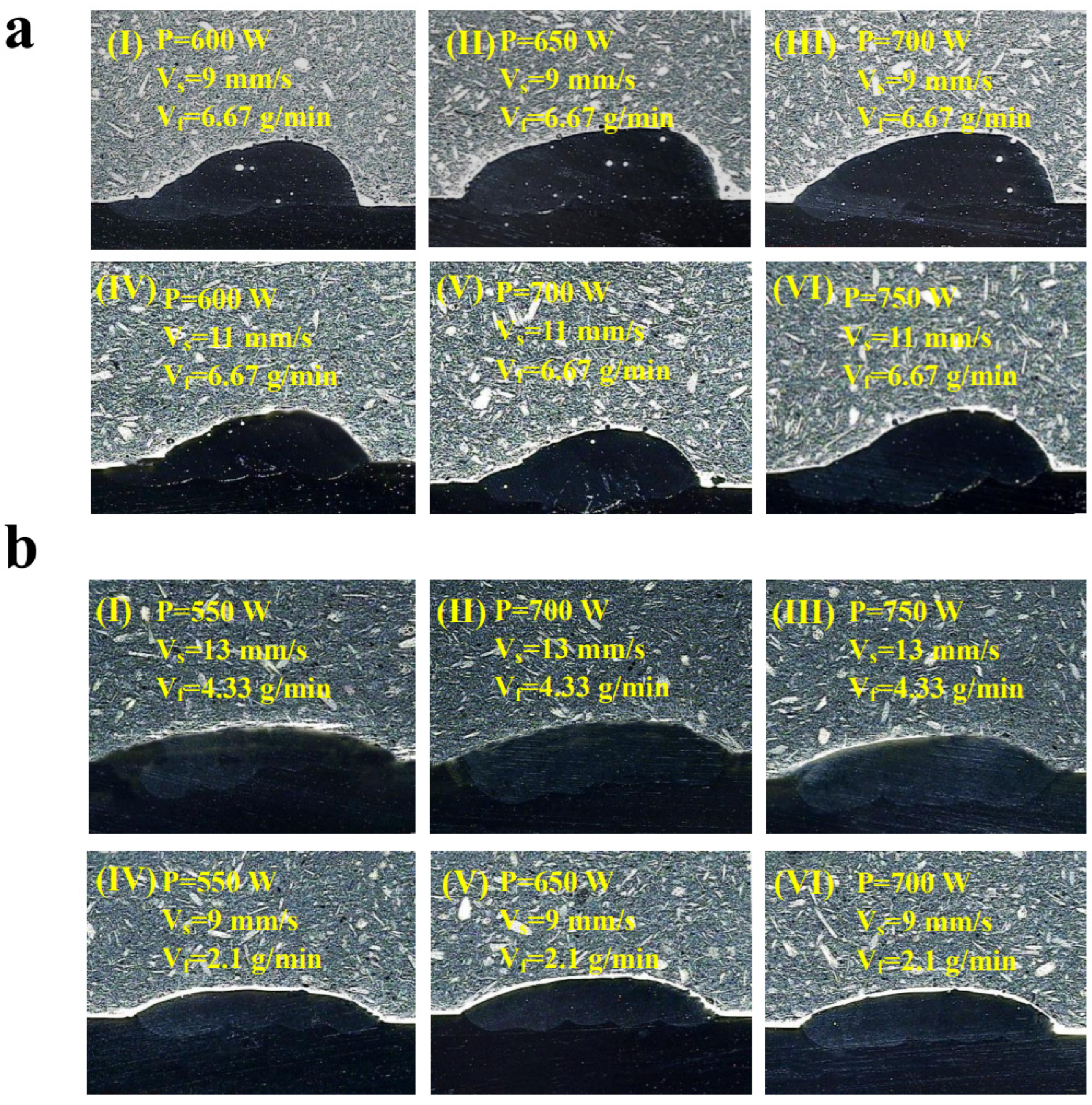
A laser power of 600~750 W, scanning speeds of 9 mm/s and 11 mm/s, and a powder feeding rate of 6.67 g/min were selected to laser additively fabricate a single multi-layer, multi-channel deposition layer. In this case, the aspect ratio ranged from 0.4 to 0.5, and the wetting angle was less than 120°. As shown in
Figure 19a, the cross-sectional morphology of the single-pass, multi-layer deposited layer exhibits a porous and pronounced steepening phenomenon. The wetting angle gradually decreases, and there are noticeable inclusions within the deposited layer, which will adversely affect the mechanical properties. On the contrary,
Figure 19b shows that six sets of single multi-layer, multi-channel deposited layers were fabricated using direct laser deposition, with a laser power of 550 W~750 W, scanning speeds of 9 mm/s and 13 mm/s, and powder feeding rates of 2.1 g/min and 4.33 g/min. The aspect ratios ranged from 0.2 to 0.3, and the wetting angles were greater than 120°. The cross-sectional morphology of group (b) shows that the surface of the deposited layers in this value range is smooth, and the defects, such as porosity and inclusions, are significantly reduced.
4. Theoretical Deduction
Wettability is an important property of a material surface, and the degree of wetting is commonly measured using the wetting angle θ [
22]. Young’s equation describes the relationship between the contact angle and the three interfacial tensions [
23]. Young’s equation, also known as the wetting equation, holds a significant position in the field of material surface interfaces. It serves as the foundation for quantifying the surface wettability of a material [
22] and calculating the surface tension of a solid material using the wetting angle [
24]. As the research progressed, it was found that Young’s equation needed to be corrected by introducing line tension when the droplets are small [
25]. The cross-section of a single-pass coating exhibits morphological similarities to the lying drop and spherical crown models. Therefore, deriving a mathematical model of the relationship between the geometrical parameters of the deposited layer by combining surface tension and gravity requires the assistance of Young’s equation, which is based on the laying drop and crown models.
Here, it is important to emphasize that the spherical crown model is solely a theoretical derivation of the cross-section parameter relationships for a single layer with a more regular single-channel cross-section morphology profile. Some irregular cross-sectional morphologies appear in
Figure 3 and
Figure 4. These irregular morphologies indicate that this parameter combination is not within the optimal range, and this particular parameter is not applicable to the theoretical derivation of the ball-and-crown model.
The model the crown of the sphere, as shown in
Figure 20, is based on the formula for the area of a circle:
The formula for calculating the volume of a spherical crown is:
And the other geometric relationships:
The associations (1)–(3):
Therefore, the crown height h, volume V, and contact area S satisfy the equation:
Equation (5) is a cubic equation, which has a unique real root determined by solving for the roots of a cubic equation in one variable:
The relationship between the crown height h, crown volume V, and contact area S, as well as the wetting angle θ and crown height h, is determined using the crown model.
However, in reality, the deposited layer’s surface will assume a spherical shape due to surface tension, as illustrated in
Figure 20. This occurs when the tension per unit length of the spherical shell is set to σ, the
Z axis serves as the axis of symmetry, and there is a difference in air pressure between the inside and outside of the spherical crown, which is denoted as ΔF.
Once the spherical shell is in equilibrium, the difference between the internal and external pressures, ΔF, must be cancelled out by the surface tension of the shell, as shown in
Figure 20.
This can be introduced as
The relationship between the wetting angle θ, crown height h, internal and external pressures P and P0, and line tension σ was determined by solving the crown model in conjunction with the surface tension.
The surface wettability of a material is influenced by three factors: the physicochemical properties of the material itself, surface tension, and gravity. A previous spherical crown model has taken into account the effect of surface tension, but it has not considered the influence of gravity on shape. When considering the effect of gravity, the analysis of the spherical crown model is performed in conjunction with Young’s equation, which is also known as the wetting equation.
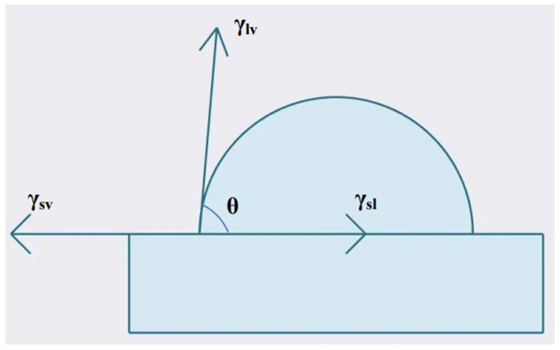
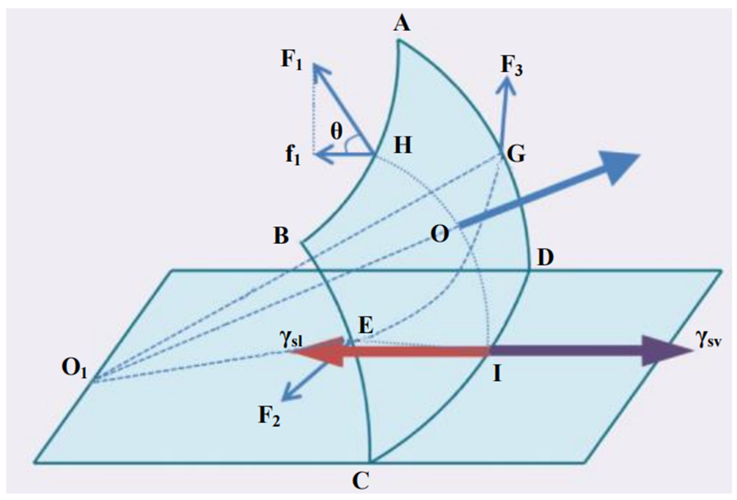
As shown in
Figure 21, the relationship between the wetting angle θ and the interfacial tension is described by Young’s equation, proposed by T. Young through mechanical analysis, i.e.,
where γ
sv represents the solid surface tension, γ
lv represents the liquid surface tension, and γ
sl represents the solid–liquid interfacial tension. Some studies [
21] have explored the relationship between gravity and the wetting angle. However, further analyses were carried out based on the schematic of the spherical crown model, in conjunction with the previously described surface tension. A small section of the rectangle ABCD is intercepted from the edge of the spherical crown, as shown in
Figure 22.
Combining
Figure 21 and
Figure 22 shows that the side AB of the small rectangle ABCD is affected by surface tension:
The component force in the horizontal direction:
Similarly, sides BC and AD are subject to surface tension:
The component force in the horizontal direction:
The surface tension on the edge CD:
Consider the case under a gravitational field and let the height of the droplet be denoted as h. The rectangle ABCD is subjected to pressure from the droplet in the direction of OO
1. The magnitude of this pressure is determined by the relationship between the force, pressure, and area:
The component force in the horizontal direction:
The reason for this is that the magnitude of the combined force in the horizontal direction is zero:
The formula tidied up is as follows:
From the relationship between the line tension σ and l, γ
lv, let γ
lv∙l=σ, then the equation can be written as
When the droplets are small and the height of the droplet is negligible, there is
When the droplets are large and the line tension is negligible, there is
Combining the relationship between the wetting angle θ, the crown height h, the internal and external pressures P and P
0, and the line tension σ, which was derived earlier based on the spherical crown model combined with the surface tension solution, and substituting it into the above equation, it can be expressed as
In conjunction with (15), there is
The novelty of this study is demonstrated by the combination of cross-sectional morphology diagrams and previously obtained data for 60 sets of process parameter combinations, in conjunction with Equation (33). The parameter values can fluctuate within different environments. When CD, ρ, g, and γlv in Equation (33) are determined, there exists a quantitative relationship between the height of the sedimentary layer h and the wetting angle θ. Based on this relationship, a set of h and θ can be determined by selecting the process parameters before conducting an experiment or engineering project. This allows us to assess whether the selected set of process parameters can produce a single-layer, single-pass morphology that meets the requirements of the latter. By selecting fewer consumables and ensuring high-level efficiency, the suitability of the process parameters can be determined to the greatest extent possible, and the wear can be minimized.


