Abstract
A new type of coating brush plating solutioncontaining stannous sulfate and potassium pyrophosphate was prepared by solution mixing method.Its structures, physicochemical properties, and the application effect in power equipment contact were also investigated by electrochemical workstation, X-ray photoelectron spectroscopy (XPS), scanning electron microsco (SEM), Mapping, and infrared thermometer. The results showed that the tin coating has good adaptability to the ambient temperature and good adhesion with the copper substrate. Cerium nitrate was evenly distributed over the tin plating layer, reduced the crystal refinement of tin and lead to a uniform distribution of microdefects. When the cerium nitrate content, the amount of additives, the amount of complex agent, and the number of brush plating operations are 0.1%, 10.0%, 8.0%, and 5 times, respectively, the tin plating layer has the best electrochemical performance. For application, the damaged contacts of power equipment can fully meet the demand of power use after being treated by the new brush plating solution.
1. Introduction
With the rapid development of electric power system and the improvement on the demand of power supply quality by consumers, the power stabilization technology is facing a new challenge. As one of the keys of power system equipment, the power electrical equipment joint’s safety relates to security and stability of power system equipment [,]. It has been found that the service reliability of power system largely relies on condition of the electrical equipment joint []. According to statistics, about 20% of power equipment failures are caused by overheating of the contact such as the guide joint and terminal post of the equipment, and almost 80% of power failures are caused by overheating of the contact during the peak period of power consumption. The contact damage to power equipment is one of the key factors that lead to joint overheating and power failure. Therefore, a variety of brushes protective coating is widely used to protect power equipment joints from corrosion or damage.
Among many brushes coating technologies, electrodeposition technology is widely used because of its high efficiency and easy operation [,,]. Electrodeposition technology mainly includes electroplating and brush plating. Brush plating is widely used to repair and strengthen the surface of parts of electric power facilities because of its advantages of light equipment, flexible process and little environmental pollution [,,].
Due to its excellent physical and chemical properties, abundant raw materials and low price, tin plating solution has become the most commonly used brush plating solution in the anticorrosion of power facilities []. Wang et al. [] prepared a tin-based coating on 316LN stainless steel, the results indicated that the coatings on stainless steel improved corrosion resistance. The traditional tin plating solution usually contains other heavy metals (such as chromium, lead, etc.), and toxic gases may be released during the brush plating process, which will cause great harms to people’s health and the environment.
Therefore, some strategies have been used to improve the brush plating solutions, such as incorporating rare earth elements. Jinet al. [] investigated the effect of rare earths (La, Ce, and Pr) on residual stress in iron coatings, the result showed that rare earth elements could purify detrimental element and absorb hydrogen atoms in the coating. Rare earth elements are important constituents of permanent magnets, rechargeable batteries, anticorrosion coatings, and catalysts [,,]. It was found that after the addition of rare earth elements, the rare earth elements will be uniformly deposited on the surface of the work piece together with the metal ions of the coating in the brush plating deposition process, which further refines the grain of the metal deposition, significantly improves the flatness, brightness and uniformity of the microscopic grain of the coating, and also reduces the cracks of the coating to a certain extent.
Among the rare earths, cerium is the most abundant, comprising 66 ppm of the earth’s crust, cerium-based oxides are attractive materials for technological applications such as catalysis, corrosion prevention, electrochemical cells, photocatalysis, UV-absorbers, biomaterials, and so on [,,,,]. Tang et al. [] prepared a cerium-oxide-based coating on AA2024 Alloy by brush plating, the results showed that the cerium oxide brush plated coatings on Al alloys improved corrosion resistance. However, there are few reports on the effects of cerium-based oxides on the repair of electrical equipment contacts of tin brush plating solution.
Therefore, the aim of this work was to develop a new type of coating tin brushes plating solution based on stannous sulfate and potassium pyrophosphate, and investigated the influences of cerium nitrate, additives, complex agent, and number of brush plating on the anticorrosion behavior of metal components. We anticipate the development of a type of coating that combines the advantages of cerium nitrate.
2. Experimental Work
2.1. Plating Composition
Preparation of the additive: 1 g ascorbic acid, 0.075 g 2-mercaptobenzothiazole, 1 g N, N-dimethylformamide, 5 g fatty alcohol–polyoxyethylene ether, 10 g polyethylene glycol 400, 2.5 g catechol, and 12.5 mL methanol were added in deionized water to make 100 mL.
Preparation of the auxiliary salt: trisodium citrate and sodium nitrate are mixed by the weight 1:1.
The composition of the plating solution is summarized in Table 1. The above drugs were added to a beaker according to the specific content and stirred by a motor-stirrer at room temperature for at least 30 min to dissolve. Then the pH of the solution was adjusted to neutral by sodium hydroxide and nitric acid.

Table 1.
Plating solution formula.
2.2. Brush Plating Process
Preparation of the activation solution: 130 g trisodium citrate dihydrate, 90 g citric acid monohydrate, and 2 g nickel chloride hexahydrate were added to a beaker with 1000 mL water, and then the pH of the solution was adjusted from 3.5 to 4 by sodium hydroxide and hydrochloric acid.
Copper pretreatment: to facilitate the experimental characterisation, the substrate was selected from pure copper sheets measuring 50 mm × 20 mm × 0.2 mm. The copper sheet were polished in one direction with 2000 mesh sandpaper for 10 times to obtain a bright and smooth surface finish. Then, the copper sheet were washed with acetone for 3 times to remove the oil on the surface of copper. After it, the treated copper sheet was reactivated with an activation solution to remove oxide on the surface of copper; then, the copper sheet were immersed in ethanol solution to later use.
Brush plating process: when the brush was plated, the anode of the power source was brushed, and the cathode was connected to the pretreated copper piece. Brush plating conditions entailed a voltage of 6.5 to 7.0 V applied at room temperature, with brush plating being used 5 to 10 times. The brush plating method and the number of brush plating operations directly affected the thickness of the tinplated layer and the surface gloss. After the brush plating was completed, the residual plating solution on the surface of the plating layer was quickly removed and dried.
2.3. Experimental Characterisation
Microstructural analysis: the microstructure of the coating on the surface of the copper substrate was analyzed by scanning electron microscopy (SEM, 300/VP, Zeiss, Jena, Germany). The surface morphology of the coating was observed to determine whether the coating was blistering, detached from the matrix, contained obvious defects, and assess its grain distribution. In addition, the contact between the two layers of the coating and the substrate could be found, and the specific thickness of the coating was visually measured through the graticule scale provided with the scanning software. The effects of trace rare earth elements on the crystallization and low-light morphology of the metal particles were compared. The cross-section of the substrate after brush plating (the cross-section of the substrate was cut by a paper cutter) was observed by SEM, and the interface between the plating layer and the copper substrate was analyzed, and the thickness of the plating layer measured.
Binding force test: in this experiment, the thermal shock test required by GB5933-86 and the requirements of GB/T 5270-2005 were combined by the scribing method to test the adhesion of the coating. The copper plate that had been plated under the same conditions (baking it at 20, 30, 50, 70, 90, and 110 °C for 2 h) was prepared, then after rapid cooling to room temperature with deionized water, a 30° sharp edge hard knife was used on the base copper coated surface of each sample when separated by 1 mm and arranged perpendicular to each other, so that the engraved line could divide the surface of the base plating into grid blocks. The requirement of the scribing was to ensure that the edge of the knife was drawn below the base metal. Finally, the processed copper sheets were magnified under a polarizing microscope for observation and analysis.
Electrochemical performance analysis: The electrochemical properties of the coating were examined with a traditional three-electrode system []. The coating was enlisted as the working electrode, while the saturated calomel electrode (SCE) and platinum wire were used as a reference electrode and a counter electrode, respectively. Before conducting the electrochemical experiment, the copper sheet on the back side of the brush plating layer was first insulated with a resin. Through polarization curve and impedance test analysis, the effects of rare earth elements, additives, complexing agents, and number of brush plating times on the electrochemical properties of the coating were compared. The surface of the copper plate (50 mm × 20 mm × 0.2 mm) was plated, and the polarization curve and impedance performance test of the brush coating was carried out in a 3.5% sodium chloride solution using a three-electrode system of calomel and platinum electrodes.
Elemental analysis: Field-emission scanning electron microscopy (FESEM, Zeiss Merlin Ultra 55, Zeiss, Jena, Germany), elemental mappings, and X-ray photoelectron spectroscopy (XPS, 250, Thermo Fisher, Waltham, MA, USA) were used to analyze the elemental and valence states of the prepared samples to determine the composition of the coating.
3. Results and Discussion
The microstructure of the coating indirectly reflects the performance of the coating. Figure 1 demonstrated the SEM images of the surfaces and cross-sections of the plating layer at different magnifications. As can be seen from the low-magnification SEM images (Figure 1a,b), the coating textures showed clear, continuous structures with some rough and similar to the microscopic grain after the copper base grinding, and negligibly changed before and after adding cerium nitrate. It can be seen from the high-magnification SEM images (Figure 1c–f) that the tin plating layer exhibited a smooth, compact, and continuous surface with a dense and small size crystal and few defects.
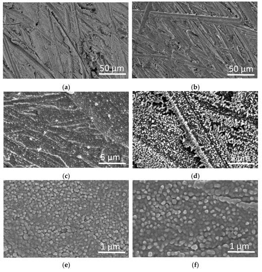
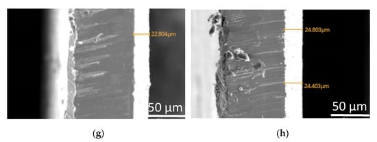
Figure 1.
SEM image of the surfaces and sections of the tin plating layer (a,c,e,g) containing cerium nitrate; (b,d,f,h) not containing cerium nitrate.
As can be seen from Figure 1d,f, the crystals of the coating without cerium nitrate had a smooth, compact, and continuous structure with some defects, which suggested that the plating solution based on stannous sulfate and potassium pyrophosphate had a good stability, thus to a dense and uniform plating effect. The addition of cerium nitrate into the plating solution led to a remarkable change in the surface topography, and a better structure was generated. A smaller, more homogenous, and denser surface structure with fewer cracks was obtained when cerium nitrate was added, which indicated that cerium nitrate was contributed to a denser and less defective coating.
Observing the SEM image of the cross-section of the coating (Figure 1g,h), it can be seen that the interface between the coating and the substrate is obvious and homogenous with a tight bond and that there are no obvious defects. At the same time, the thickness of the plating layer exceeds 22 μm, and the thicknesses of the plating layers in Figure 1g,f are similar. The results show that the rare earth cerium nitrate could improve the microstructure of the coating but not have a significant effect on the thickness of the coating. In industrial applications, the thickness of the plating layer can be adjusted to some extent by controlling the number of plating operations.
The copper-based tin-plated layer was treated at different ambient temperatures (from 20 to 110 °C), and the surface quality of the coating was magnified 50 times using a polarizing microscope and showed in Figure 2. It can be seen from the figures that in the temperature range of the experimental treatment, there is no shedding or foaming on the surface of the coating, and the surface is still smooth and flat; the tin-plated layer at the scratch remains in close connection with the copper matrix and does not exhibit defects such as shedding and foaming. The results showed that the coating exhibits strong adhesion to the copper substrate, and the basic performance of the tin-plated layer obtained by the process is unaffected by the temperature change within a certain range of ambient temperatures.
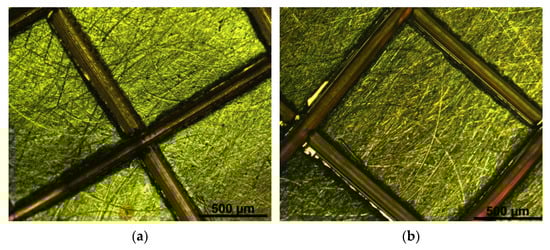
Figure 2.
Microscopic enlargement of the coating after treatment at different temperatures (a) 20 °C, (b) 30 °C, (c) 50 °C, (d) 70 °C, (e) 90 °C, (f) 110 °C.
The tin whiskers begin to slowly elongate under the action of high temperature, high humidity, and external stress. Figure 3 shows the micrographs of the coating before and after treatment for 7 days at 55 °C and 85% humidity. Figure 3d,f are the plating diagrams when bent to 90°. It can be seen that the crystal structure of the plating layer before and after treatment was similar; only the crystal grains of the coating layer without adding cerium nitrate and subjected to bending through 90° were laterally elongated, and whiskers start to appear. The results showed that the coating of this system can inhibit the elongation of whiskers.
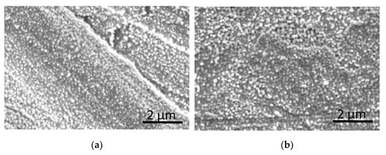
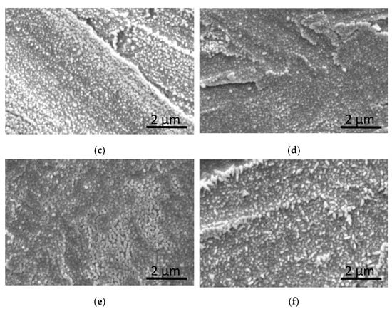
Figure 3.
SEM image of the surface and section of the tin plating(a,c,e) containing cerium nitrate; (b,d,f) not containing cerium nitrate; (a,c,d) before treatment; (b,e,f) after treatment.
The 0 line segment of the four figures is a Tafel curve of pure copper. Figure 4a shows the samples with different amounts of cerium nitrate: 1–0%; 2–0.05%; 3–0.1%; 4–0.15%. Figure 4b shows the samples with different amounts of additive: 1–0%; 2–5.0%; 3–10.0%; 4–15.0%. Figure 4c shows the samples with different amounts of complexing agent: 1–0%; 2–4%; 3–8%; 4–12%. Figure 4d shows the samples with different times of brush plating operations: 1–2 times; 2–5 times; 3–8 times).
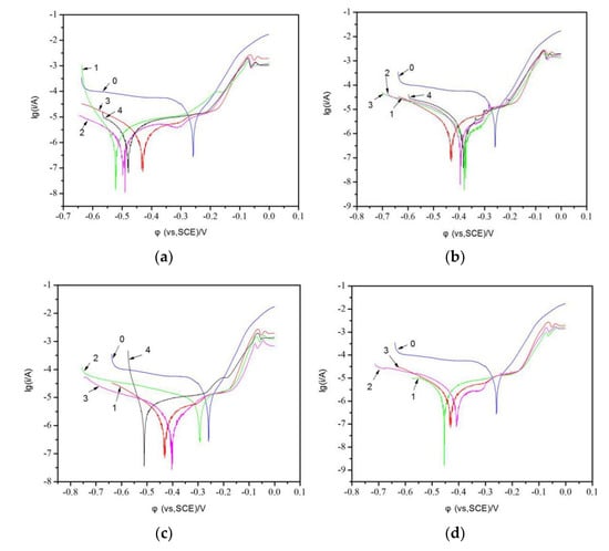
Figure 4.
Plating electrochemical workstation Tafel polarization curve. (The 0 line segment of the four figures is (a) Tafel curve of pure copper; a showed the samples with different amounts of cerium nitrate: 1–0%; 2–0.05%; 3–0.1%; 4–0.15%; (b) showed the samples with different amounts of additives: 1–0%; 2–5.0%; 3–10.0%; 4–15.0%; (c) showed the samples with different amounts of complexing agent: 1–0%; 2–4%; 3–8%; 4–12%; (d) showed the samples with different times of brush plating operations: 1–2 times; 2–5 times; 3–8 times.)
As shown in Figure 4 and Table 2, there are different levels of cerium nitrate, additives, complexing agents, different times on the Tafel curves and eigenvalues of copper layer. As can be seen, the corrosion potential and corrosion current of the tin plating layer were obviously lower than that of the copper sheet, which suggested that the tin plating was more susceptible to corrosion than the pure copper, but the tin plating is etched at a lower rate than the pure copper. Comparing the polarization curves in Figure 4a–d, it can be seen that the cerium nitrate content, additive content, complexing agent content, and number of brush plating operations had no effect on the corrosion current and corrosion rate of the coating. With the increase of cerium nitrate content, additive content, complexing agent content, and brush plating times, the corrosion potentials tended to first decrease and then increase, indicating that these four variables have an effect on the corrosion resistance of tin plating, but the corrosion current changed negligibly. The self-corrosion rate of metal increased with the increased of self-corrosion current; however, the corrosion resistance of metal improved with the increased of self-corrosion voltage. Those data indicated that the incorporating appropriate of cerium nitrate, complexing agent, and additive to the plating solution could enhance the corrosion resistance of tin coating.
Table 2.
Corrosion current and corrosion voltage of tin plating under different influencing factors.
Figure 5 showed the impedance curves of pure copper and tin plating. It was found that in the low frequency region, the slopes of both curves were basically 1; however, in the high frequency region, the arc of curve 2 was larger than that of curve 1. In other words the impedance of tin plating was higher than that of pure copper, which indicated that tin coating could enhance the corrosion resistance of metal matrix.
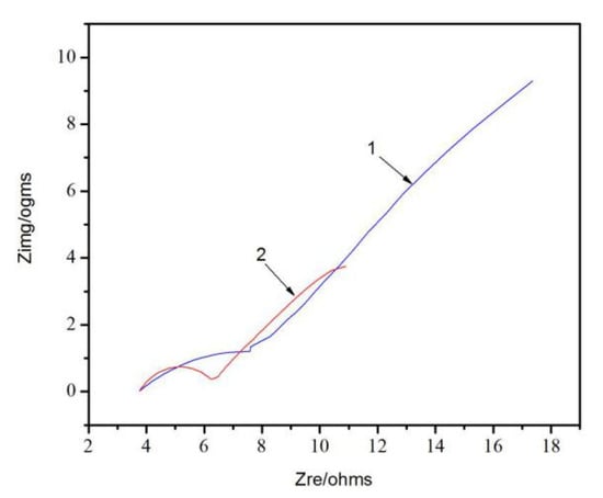
Figure 5.
Impedance curve of copper surface before and after brush plating. (Curve 1: pure copper sheet; Curve 2: tin plating layer).
As shown in Figure 6 and Figure 7, the elemental composition of the coating and the valence of the element were characterized by combination of element mapping and XPS spectroscopy. The elemental composition of the coating can be clearly seen, the tin element was uniformly coated on the surface of the copper layer substrate, and the small amount of cerium element was homogeneously dispersed in the tin coating layer, which showed that the coating solution has good stability and homogeneity. To further verify the valence state of Sn and Ce in the coating layer, XPS analysis of the coating was conducted. Figure 7a,b show that main peaks appeared at 486.3and 494.6 eV, which corresponds to Sn 3d3/2 and Sn 3d5/2, respectively, indicating that Sn atoms were in oxidation state of Sn4+, thus verifying that Sn was coexisted in the coating sample as compounds [,]. The peaks of Ce 3d contained two peaks: V (885.7 eV) and U (905.4 eV) in Figure 7c, where the peak marked V and U were assigned to Ce 3d3/2 and Ce 3d5/2, respectively. The peaks labeled V and U were all related to Ce3+ [,].
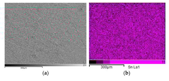
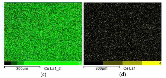
Figure 6.
Elemental mapping diagram of the tin plating. (a) electron image, (b) distribution of tin, (c) distribution of copper, and (d) distribution of cerium.
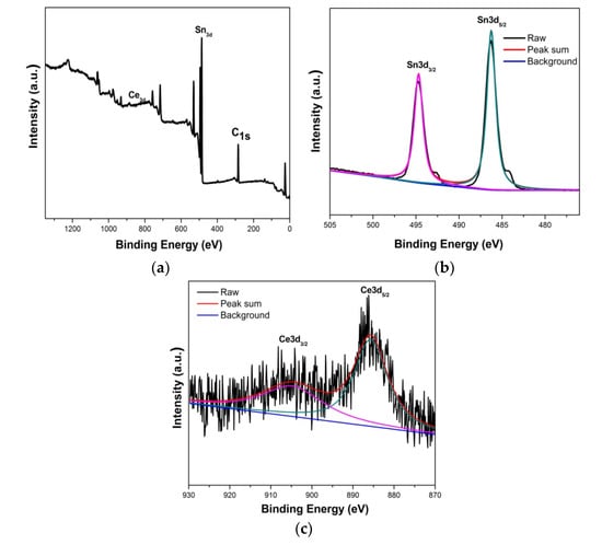
Figure 7.
XPS spectra: tin plating. (a) Total peak figure, (b) Satellite peak of tin, (c) Satellite peak of cerium.
According to the above experimental data, when cerium nitrate content, the amount of additives, the amount of complexing agent, and the number of brush plating operations were 0.1%, 10.0%, 8.0%, and 5 times, respectively, the coating had the best properties; therefore, this formula of the coating solution was used for subsequent application experiments.
4. Application
After power equipment runs for a period of time, the contacts, especially outdoor equipment, such as transformers, circuit breakers, disconnectors, voltage, and current transformers show corrosion, oxidation, damage and other problems that cause abnormal heat and lead to a power failure. Therefore, these parts need to be repaired regularly. Figure 8 shows the main equipment usually used in the electrical equipment repair process, including brush plating power supply and brush plating pen. Figure 9 shows the grinding and brush plating process of electric equipment during field brush plating.
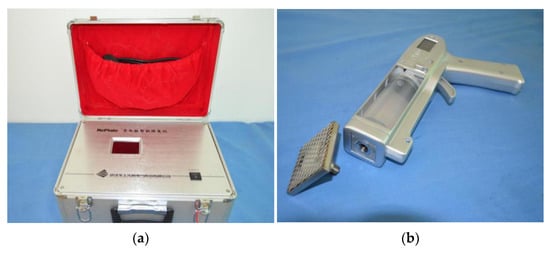
Figure 8.
Brush plating main tool. (a) Brush plating power supply, (b) brush plating pen.
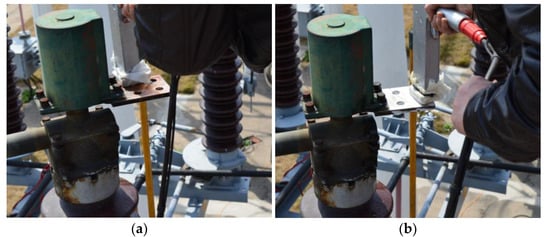
Figure 9.
On-site brush plating processing diagram for large instrument parts. (a) brush plating before, (b) brush plating after.
In order to explore the repair effect of the brush plating solution on electric equipment, an infrared thermometer was used to measure the temperature of the disconnecting switch before and after the repaired by the tin coating solution. As can be seen from Figure 10, before repair, the disconnecting switch showed a high temperature at 122 °C during full load operation; however, a low temperature of 35 °C was found when the disconnecting switch repaired with the tin coating solution. This phenomenon showed that the coating solution system could effectively repair the power equipment, reduce the contact resistance of the disconnecting switch, and effectively solve the abnormal heating phenomenon during the normal operation of the equipment.
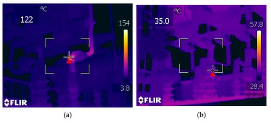
Figure 10.
Infrared temperature measurement on running equipment. (a) before brush plating; (b) after brush plating.
5. Conclusions
A new type of coating brush plating solution was obtained using stannous sulfate, potassium pyrophosphate, and cerium nitrate through mixing and was then used for repairing the disconnecting switch. Results indicated that good stability, dispersion, and corrosion resistance of the coating solution could be obtained by using the appropriate content of stannous sulfate, potassium pyrophosphate, cerium nitrate, and so on. The tin plating layer of the brush plating on the copper substrate had good adhesion, the thickness of the coating could reach 24 μm, and the tin ions were fine and uniform. The cerium nitrate could further refine the grains of tin ions to make the material more uniform, denser, and less defective. When cerium nitrate content, the amount of additives, the amount of complexing agent, and the number of brush plating operations were 0.1%, 10.0%, 8.0%, and 5times, respectively, the coating had the best physicochemical properties, best corrosion resistance, and lowest cost. In application, the tin coating solution could effectively repair the damaged disconnecting switch. This system based on the coating solution showed potential for repairing electrical equipment.
Author Contributions
Investigation, Z.M.; Project administration, W.L.; Supervision, C.H. and C.Q.; Writing—original draft, K.Z. All authors have read and agreed to the published version of the manuscript.
Funding
This project was supported by the Science and Technology Department of Hubei Province of China (Grant No. 2018ACA152). Research Project of Hubei Provincial Department of Education (Grant No. B2015041).
Institutional Review Board Statement
Not applicable.
Informed Consent Statement
Not applicable.
Data Availability Statement
Data sharing is not applicable to this article.
Conflicts of Interest
The authors declare no conflict of interest.
References
- Seki, K.; Tsuchida, T.; Oka, N.; Sugihara, H.; Akiba, A.; Hiroki, T.; Tada, H.; Yamazaki, M.; Sekioka, S. Earth system and improvement plan for shield of cable with separable connector. In Proceedings of the 2018 34th International Conference on Lightning Protection (ICLP), Rzeszow, Poland, 2–7 September 2018; pp. 1–6. [Google Scholar]
- Vera, R.; Delgado, D.; Rosales, B. Effect of atmospheric pollutants on the corrosion of high power electrical conductors—Part 2. Pure copper. Corrison Sci. 2007, 49, 2329–2350. [Google Scholar] [CrossRef]
- Vera, R.; Delgado, D.; Rosales, B. Effect of atmospheric pollutants on the corrosion of high power electrical conductors: Part 1. Aluminium and AA6201 alloy. Corrison Sci. 2006, 48, 2882–2900. [Google Scholar] [CrossRef]
- Ren, Y.; Deng, H.; Huang, F.; Xu, Q. Research progress of brush plating technology in surface engineering. Surf. Technol. 2013, 42, 83–87. [Google Scholar]
- Kim, G.; Kim, Y.; Kim, H. Review of brush painting for cost-efficient paintable electronics. Appl. Sci. Converg. Technol. 2021, 30, 1–5. [Google Scholar] [CrossRef]
- Li, Q.; Qin, G.; Huang, J.; Gui, C.; Bei, J.; Huang, H.; Li, P.; Dong, Q.; Chen, Z. Polymer brush-induced electroless copper plating to fabricate Cu/CaCO3composite powder. Surf. Rev. Lett. 2021, 28, 2050053. [Google Scholar] [CrossRef]
- Zhong, Z.; Clouser, S. Nickel-tungsten alloy brush plating for engineering applications. Surf. Coat. Technol. 2014, 240, 380–386. [Google Scholar] [CrossRef]
- Liu, H.; Wang, X.; Ji, H. Fabrication of lotus-leaf-like superhydrophobic surfaces via Ni-based nano-composite electro-brush plating. Appl. Surf. Sci. 2014, 288, 341–348. [Google Scholar] [CrossRef]
- Huang, J.; Gui, C.; Ma, H.; Li, P.; Wu, W.; Chen, Z. Surface metallization of PET sheet: Fabrication of Pd nanoparticle/polymer brush to catalyze electroless nickel plating. Compos. Sci. Technol. 2021, 202, 108547. [Google Scholar] [CrossRef]
- Walsh, F.C.; Low, C.T.J. A review of developments in the electrodeposition of tin. Surf. Coat. Technol. 2016, 288, 79–94. [Google Scholar] [CrossRef] [Green Version]
- Wang, X.; Li, S.; Peng, J. Corrosion Behaviors of 316LN Stainless Steel Joints brazed with Sn-plated silver filler metals. Int. J. Mod. Phys. B 2018, 32, 1850198. [Google Scholar] [CrossRef]
- Jin, G.; Lu, B.; Hou, D.; Cui, X.; Song, J.; Liu, E. Influence of rare earths addition on residual stress of Fe-based coating prepared by brush plating technology. J. Rare Earths 2016, 34, 336–340. [Google Scholar] [CrossRef]
- Rahbar, M.; Shannon, L.; Gray, B.L. Design, fabrication and characterization of an arrayable all-polymer microfluidic valve employing highly magnetic rare-earth composite polymer. J. Micromechan. Microeng. 2016, 26, 055012. [Google Scholar] [CrossRef]
- Cao, Y.; Li, H.; Zhang, J.; Shi, L.; Zhang, D. Promotional effects of rare earth elements (Sc, Y, Ce, and Pr) on NiMgAl catalysts for dry reforming of methane. RSC Adv. 2016, 6, 112215–112225. [Google Scholar] [CrossRef]
- Agafonov, R.Y.; Vilkov, F.E.; Kasitsyn, A.N.; Predko, P.Y.; Marchenkov, A.Y. Aluminum based alloys with rare-earth metals additives application for rocket-and-space engineering. Metallurgy 2016, 23, 174–180. [Google Scholar]
- Song, G.; Cheng, N.; Zhang, J.; Huang, H.; Yuan, Y.; He, X.; Luo, Y.; Huang, K. Nanoscale cerium oxide: Synthesis, biocatalytic mechanism, and applications. Catalysts 2021, 11, 1123. [Google Scholar] [CrossRef]
- So, Y.M.; Leung, W.H. Recent advances in the coordination chemistry of cerium (IV) complexes. Coord. Chem. Rev. 2017, 340, 172–197. [Google Scholar] [CrossRef]
- Castano, C.E.; O’Keefe, M.J.; Fahrenholtz, W.G. Cerium-based oxide coatings. Curr. Opin. Solid State Mater. Sci. 2015, 19, 69–76. [Google Scholar] [CrossRef]
- Xu, J.; Yu, H.; Zhang, C.; Guo, F.; Xie, J. Development of cerium-based catalysts for selective catalytic reduction of nitrogen oxides: A review. New J. Chem. 2019, 43, 3996–4007. [Google Scholar] [CrossRef]
- Arshad, T.; Khan, S.A.; Faisal, M.; Shah, Z.; Akhtar, K.; Asiri, A.M.; Ismail, A.A.; Alhogbi, B.G.; Bahadar Khan, S. Cerium based photocatalysts for the degradation of acridine orange in visible light. J. Mol. Liq. 2017, 241, 20–26. [Google Scholar] [CrossRef]
- Tang, J.; Han, Z.; Zuo, Y.; Tang, Y. A corrosion resistant cerium oxide based coating on aluminum alloy 2024 prepared by brush plating. Appl. Surf. Sci. 2011, 257, 2806–2812. [Google Scholar] [CrossRef]
- Zou, Y.; Cai, C.; Xiang, C.; Huang, P.; Chu, H.; She, Z.; Xu, F.; Suna, L.; Kraatz, H.-B. Simple synthesis of core-shell structure of Co-Co3O4 @ carbon-nanotube-incorporated nitrogen-doped carbon for high-performance supercapacitor. Electrochim. Acta 2018, 261, 537–547. [Google Scholar] [CrossRef]
- Meng, X.; Tian, H.; An, X.; Yuan, S.; Fan, C.; Wang, M.-J.; Zheng, H.-X. Field effect transistor photodetector based on two dimensional SnSe2. Acta Phys. Sin. 2020, 69, 137801. [Google Scholar] [CrossRef]
- Modiba, F.; Arendse, C.J.; Oliphant, C.J.; Jordaan, W.A.; Mosterta, L. Evolution of the chemical composition of Sn thin films heated during x-ray photoelectron spectroscopy. Surf. Interfaces 2019, 17, 100378. [Google Scholar] [CrossRef]
- Tao, X.; Cong, W.; Huang, L.; Xu, D. CeO2 photocatalysts derived from Ce-MOFs synthesized with DBD plasma method for methyl orange degradation. J. Alloys Compd. 2019, 805, 1060–1070. [Google Scholar] [CrossRef]
- Xiao, K.; Liang, F.; Liang, J.; Xu, W.; Liu, Z.; Chen, B.; Jiang, X.; Wu, X.; Xu, J.; Beiyuan, J.; et al. Magnetic bimetallic Fe, Ce-embedded N-enriched porous biochar for peroxymonosulfate activation in metronidazole degradation: Applications, mechanism insight and toxicity evaluation. Chem. Eng. J. 2022, 433, 134387. [Google Scholar] [CrossRef]
Publisher’s Note: MDPI stays neutral with regard to jurisdictional claims in published maps and institutional affiliations. |
© 2022 by the authors. Licensee MDPI, Basel, Switzerland. This article is an open access article distributed under the terms and conditions of the Creative Commons Attribution (CC BY) license (https://creativecommons.org/licenses/by/4.0/).