Abstract
This study was concerned with the adhesion of resin cement to metal surfaces obtained by selective laser melting process (SLM), and how it could be improved the bond strength at the biocomposite-metal junction. The SLM substrates were manufactured out of pure titanium (Ti), Ti6Al7Nb, and CoCr alloys. The metallic surfaces were covered with 5 types of biocomposites: 2 commercially resin-modified glass-ionomer cements (GC Fuji Plus and KETAC CEM) and 3 types of in-house developed materials. These biocomposites were mechanical characterized under compression and bending trials. The biocomposites-metal adhesion was settled both on as built metallic surfaces and after they were sandblasted with alumina. All the sandblasted SLM surfaces presented higher adhesion strength in comparison with the untreated specimens. The CoCr specimens show the highest bonding value. Additionally, the morphological aspects of joining interfaces were investigated using a scanning electron microscope (SEM). The mechanical properties and metal adhesion of these biocomposites were influenced by the liquid powder ratio. It is essential to apply a surface treatment on SLM substrate to achieve a stronger bond. Also, the chemical composition of biocomposite is a major factor which may improve the adhesion of it on different metallic substrates.
1. Introduction
The composition of the implant material and its surface characteristics are of special interest in implantology, as they initially influence the fibrin binding capacity and growth factor release, thus affecting the direct migration of mesenchymal cells [1].
The oral environment is also conducive to corrosion in which the metal is attacked by the presence of natural agents (air and water), temperature fluctuations (hot and cold), and changes in pH due to feeding, resulting in the partial or complete dissolution, damage, or weakening of any solid substance [2]. Establishing a surface which generates an optimal composition and conformation for the attachment of osteogenic cells to the surface is one of the most important production strategies. In recent years, several methods have been developed to produce nanoscale structures on the surface of titanium (Ti). Nano-biomaterials have a high percentage of atoms and crystalline structures and provide a larger surface area than conventional ones. Thus, nanoscale surfaces have a high surface energy, which increases the initial adsorption of proteins. This factor is very important in regulating cellular interactions on the implant surface.
Various conventional and unconventional processing operations are used to manufacture biomedical implants. After implant fabrication, various post-processing treatments can improve the bioactivity and biocompatibility capabilities [3,4]. To improve the biomechanical anchoring of the implant and to promote histological osseointegration [5], changing the surface topography or covering metal implants with bioactive materials has captured the interest of many scientists, clinicians, and manufacturers [6,7]. The additive manufacturing (AM) becomes an emergent method developed to produce complex and customized medical applications [8,9,10]. There are several types of post-processing tests to improve the performance of AM components as following: laser re-melting, heat treatment, hot isostatic pressing (HIP), and shot peening [11]. Specifically, the materials processed are hard and strong, with improved corrosion properties, fatigue strength, and extraordinary tribological properties. The practice commonly used to induce this effect is commercially known as ‘shot peening’, in which the surface is bombarded with small, spherical, hard metal, glass, or ceramic particles at speeds high enough to create SPD [12].
Selective laser melting (SLM), is a rapid prototyping, 3D printing, or additive manufacturing (AM) technique designed to use a high power-density laser to melt and fuse metallic powders together. The SLM technology is a complex thermo-physical and metallurgical process influenced significantly by the following parameters: laser power, scanning speed, hatch distance, layer thickness, and scanning strategy. In this field, the selective laser melting (SLM) process was optimized for Ti or CoCr alloys, and today it is possible to fabricate different types of clinical applications such as dental crowns or bridges, maxillofacial reconstructions, knee or hip prostheses, stents, spine implants, and grafts for bone regeneration [13,14,15]. After SLM manufacturing, the metallic surfaces are modified by sandblasting, etching, anodizing, chemical treatments or deposition of biocomposites. Each of these methods has been applied to improve the implant stability and to augment the osseointegration process. The disadvantages of customized implants include palpability, sensitivity to temperature changes, stress shielding of the underlying bone, growth restrictions, and the spread of undesirable metallic articles in the soft tissue and regional lymph nodes, and possibly mutagenic effects [16]. Consequently, new research is required to limit this disadvantage. A biocomposite interface between metallic surface and host bone could be a possible route. This aspect emphasizes the compulsion to develop a biocomposite that can meet the medical requirements from mechanical perspective (Young’s modulus and compression strength), and it also should improve the shear bond strength to metallic surfaces SLM manufactured. Covering the SLM metallic surfaces with biocomposites also offer the following advantages: limited corrosion, absence of release of metal ions which are harmful for the organism, and improved resistance to tearing and fatigue [17]. In this topic, insufficient adhesion strength between biocomposite and SLM metals can causes microscopic gaps leading to serious clinical problems [18]. Therefore, it is crucial to create strong and durable adhesion. Pure Ti and Ti6Al4V alloy are used in surgery applications because of their good biocompatibility, explained by their physical–mechanical properties and by the fact that their surfaces are always covered with a thin TiO2 layer. This nanometric layer is responsible for corrosion resistance and its bioinert behavior in vivo, which leads to acceptable osseointegration. Currently, implants are processed through additive and subtractive manufacturing [19]. The clinical practice has shown that the medical applications made of pure Ti limit significantly the risk of allergic reactions after implantation [20]. Furthermore, Ti6Al7Nb alloy is characterized by higher corrosion resistance and biotolerance in comparison with commonly used Ti6Al4V alloy [21,22]. Thus, these two metals assisted by biocomposites represent a promising approach to develop advance medical applications, motivating the present work.
Many reports investigated the bond strengths between biocomposites and CoCr metal frameworks, which possess better biocompatibility as well as higher resistance to corrosion and tarnish than do Ni–Cr-based alloys and did not elicit adverse oxidative stress or cellular toxicity responses [23,24,25]. Different studies also focused on adhesive bonding of biocomposite to Ti surfaces manufactured with conventional techniques such as casting or CAD-CAM milling [26,27,28,29,30]. However, information is lacking about the bond strength between biocomposites and Ti surfaces fabricated by SLM method.
This study was concerned with the bonding of resin cement to the SLM metals surface and how it could improve the bond strength at the biocomposite metal junction. The aim of this study was to develop 3 biocomposites (produced at “Raluca Ripan” Chemistry Research Institute in Cluj-Napoca, Romania), to determine their mechanical properties, and to examine the bond strength. To compare the results, 2 commercial biocomposites were considered in this experimental investigation (resin-reinforced glass ionomers: Ketac Cem and GC Fuji Plus). The SLM substrates were made of pure Ti (Grade 1), Ti6Al7Nb, and CoCr alloys. These metals are suitable to fabricate customized implants. Additionally, the bond strength interface was tested both on as built metallic surfaces and after they were sandblasted with alumina.
2. Materials and Methods
2.1. Manufacturing and Controls of Metal Structures
One hundred and sixty substrates were manufactured out of 4 types of alloys: pure Ti Grade 1 (n = 40), Ti6Al7Nb (n = 40), CoCrWMo (n = 40) and CoCr (n = 40). The specimens were SLM manufactured which involves vector scanning of the deposited powder using a laser beam. The present metallic substrates were fabricated under “slice by slice” principle using a Realizer SLM 250 machine (ReaLizer GmbH, Borchen, Germany). The core component of this manufacturing system is the solid fibber laser type Nd:YAG (neodymium-doped yttrium aluminum garnet Nd: Y3Al5O12). It emits a continuous light radiation in the infrared spectrum with a 1064 nm wavelength.
The metallic powders used for manufacturing had a spherical grain produced by gas atomization process. The Ti powder has purity around 99.5% (Grade 1) and it respect the UNS R50250 standard [31]. The particles diameter ranges from 14 µm to 50 µm (Osaka Titanium Technologies, Amagasaki, Japan). The Ti6Al7Nb powder has particles between 20 µm and 63 µm (TLS Technik Spezialpulver, Bitterfeld-Wolfen, Germany) and its chemical composition is detailed in Table 1 [28]. The CoCrWMo powder has a grain size between 5 µm to 45 µm (Scheftner, Mainz, Germany) and the chemical composition complies with standard ISO 22674 [32]. The CoCr powder contain grains between 10 µm to 65 µm (MCP HEK Tooling, Lübeck, Germany) and the chemical composition comply with standard ASTM F75 [33] for surgical implants.

Table 1.
Chemical composition of alloy.
Based on previous studies and our knowledge of SLM manufacturing [34,35], some process parameters were preliminarily tested. The laser scanning strategy adopted was X/Y which allows a scanning in X direction of “n” layer and in Y direction of “n + 1” layer (rotating each hatch scan 90°). Table 2 presents the established SLM parameters which were programmed to melt both the outer boundary and the hatch area of the metallic substrates. The rectangular parallelepiped specimens (10 mm × 10 mm × 5 mm) were manufactured vertical on the Realizer SLM platform. During the SLM process, the specimens were anchored and sustained by block support structures with 1 mm distance between them. The SLM platform was uniformly preheated at 250 °C during the fabrication, under a high-purity Ar-atmosphere and limited oxygen level (0.3–0.5%). After manufacturing, half of the specimens were sandblasted [28,36].
Table 2.
Process parameters of SLM equipment for the manufacture of specimens required for adhesion tests.
The post-processing method applied was sandblasting with aluminum oxide (120 µm grain size, 4 bars pressure), keeping 5 cm distance between the nozzle and the specimens at an angle of 45 degrees. After this procedure, the SLM surfaces were ultrasonically cleaned for 10 min before the application of biocomposites [37].
The surface roughness of SLM specimens was measured before and after sandblasting, and it was done according to ISO 4287 [38] using a contact profilometer (SJ-2010; Mitutoyo Co, Kawasaki, Japan). Five measurements were done on each metallic substrate at 1 mm distance and perpendicular to the building layers, being focused on Ra, Rq, and Rz parameters. These roughness parameters were calculated as following:
where Ra is the arithmetical mean of the absolute values of the profile deviations from the mean line of the roughness profile, Rq is the root mean square average of the profile heights over the evaluation length, and Rz is the average value of the absolute values of the highest profile peaks and the deepest valleys within the evaluation length.
2.2. Manufacturing and Controls of Biocomposite Materials
Five biocomposites materials were developed to establish certain technological parameters. Three types of experimental biocomposite samples (noted cement P1, cement P2, cement P3) were produced at “Raluca Ripan” Chemistry Research Institute in Cluj-Napoca, Romania. On the other hand, two commercial resin-modified glass-ionomer cement were considered (GC Fuji Plus–GC Corporation, Tokyo, Japan; KETAC CEM–3M ESPE, St. Paul, MN, USA). The difference between them consists in the use of different ratios of the organic and inorganic phase. These materials have a chemical initiation systems and their polymerization was carried out by mixing two pastes. The composition of the biocomposite samples is shown in Table 3.
Table 3.
Chemical composition of the biocomposite samples.
This study design encompasses a wide range of mechanical properties, such as the Young’s modulus, elongation at break, and stiffness. Thus examines a wide range of stress behaviors for biocomposite samples [39,40]. The mechanical properties were performed at a room temperature of 23 °C using a universal testing machine Lloyd LR5k Plus (Lloyd Instruments, Ameteklns, West Sussex, England), at a crosshead speed of 1 mm/min, and the data were processed using Nexygen software (4.0 version). The specimens (n = 10) were polymerized according to the manufacturer’s conditions at the specific dimensions according to ISO 4049 [41]. Three different types of mechanical tests were performed. The compressive test indicates the rigidity of the material, the compressive strength curve, and the break point. These properties were determined using the Nexygen software; each compression sample must have the dimensions of 6 mm height and 3 mm diameter. For diametral tensile strength test, each specimen was prepared with the following dimensions: 3 mm diameter and 6 mm height. The flexural strength test and the Young modulus was determinate using the three-point method. For this test, rectangular bar specimens were prepared with the following dimensions 2 mm thickness, 2 mm height, and 25 mm length. The specimens were stored in distilled water for 24 h at 37 °C prior to all mechanical tests.
2.3. Morphology and Adhesion Test
These mechanical and bonding trials was performed by using a Lloyd LR5k Plus dual-column mechanical testing machine, at a crosshead speed of 1 mm/min. The data were processed using Nexygen software. The study design is illustrated in Table 4 where it can be identified the structure of each biocomposites-metal sample.
Table 4.
The chemical composition of biocomposite samples
To determine the morphology of the materials used in this study, the results obtained in the mechanical test for the assessment of the strength of the metal-ceramic bond, the INSPECT S scanning electron microscope (FEI Co, Hillsboro, OR, USA) was used as an indirect method of evaluation. In order to highlight the remaining amount of biocomposite in the metal structure, the joining interface was investigated at low vacuum.
2.4. Statistical Analysis
The statistical difference between biocomposites, for each mechanical tests were evaluated using one-way ANOVA test, and Tukey test for post hoc comparisons between groups. The significance level was set at α = 0.05, using Origin2019b Graphing & Analysis software (version 2019B). All the values in text and figures are expressed as mean ± standard deviation. The null hypothesis is that the means of all levels are equal. The results were considered significant for p ≤ 0.05. The study groups (see Table 3) are the 5 different biocomposites, and the comparison was made between all of them, for each mechanical test, each group being represented by n = 10 results.
The obtained data, of adhesion tests, were analyzed statistically with one-way ANOVA test and Tukey post hoc test, the null hypothesis being the mean of all levels are equal, at the 0.05 level. Using Origin2019b Graphing & Analysis software, all the values in text and figures are expressed as mean ± standard deviation. The study groups (Table 4) are the 4 metallic surfaces covered with 5 types of biocomposites, the comparison being made between sandblasted and not sandblasted samples, each group being represented by n = 10 results.
3. Results
3.1. The Surface Roughness of Metal Structures
Figure 1 presents a typical surface profile obtained on SLM specimens. The SLM micro-topography indicates that the surface profiles contain specific voids, valleys, and peaks with irregular step. Based on surface profiles, the Ra, Rq, and Rz roughness parameters were calculated [42].
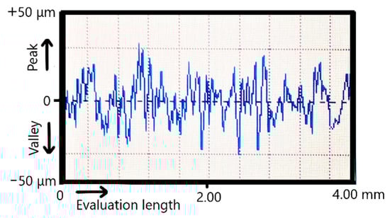
Figure 1.
Typical surface profile of SLM specimens.
Because the CoCrWMo powder was the finest one, after SLM manufacturing the measured surface roughness was the most reduced (Ra = 8.5 µm, see Table 5). On the other hand, the surface hardness influences the effect of sandblasting. Generally, the CoCr surfaces SLM-manufactured possess an exceedingly hardness between 500 HV to 570 HV [43]. As reported previously, the hardness measured on SLM surfaces made of pure Ti surfaces ranged from 229 HV to 251 HV [44] and from 330 HV to 370 HV for Ti6Al7Nb [45]. Because the pure Ti had the lowest hardness, the sandblasting procedure reduced the Ra surface roughness from 10.4 µm to 5.8 µm. Due to increased surface hardness, the sandblasting of CoCr specimens was limited compared to pure Ti. Thus, the Ra surface roughness of CoCr was initially 10.8 µm and after it were sandblasted with alumina, the values was reduced just to 7.8 µm. Similar results were also reported on CoCr surfaces after they were sandblasted [46,47,48].
Table 5.
Influence of sandblasting on surface roughness (mean ± standard deviation).
3.2. Mechanical Properties of Biocomposite Materials
It is shown that the resistance to compression can be improved by increasing the amount of BisGMA monomers (Figure 2), the fracture strain of the experimental samples changing from 34% to 17%, with statistical differences between groups (p = 2.51488 × 10⁻¹¹). Cement P1 has a good combination of mechanical properties such as high compressive strength and flexural strength. Compared to the other two experimental samples (P2 and P3), the small ratio between the amount of base monomer and the dilution monomer reduces the resistance, and the viscosity of BisGMA increases the bending resistance.
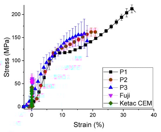
Figure 2.
The strain stress curve for biocomposites compression test (mean ± standard deviation).
Under diametral tensile test, the strength curve of materials takes a completely different appearance (Figure 3). These experimental trials reveal that the cement P2 had the highest values of stress (35 ± 7.1 MPa) and strain (17 ± 4.3%), followed by cement P1 and cement P3. On the other hand, the commercial materials had a significant improved of diametral tensile strength (up to 3 times higher, 89.91 ± 5.88 MPa), with statistical differences between them (p = 1.1883 × 10⁻¹¹). The stress-strain curves of the commercial samples are different for the compression and traction curves due to the order values of 10−2 plastic strain, indicating that this sample has the weakest plasticity. The highest stress values are recorded by GC Fuji diametral tensile strength (Figure 4). Ketac CEM demonstrates a reduced value of tensile strength even if it contains 80% filler.
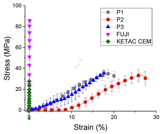
Figure 3.
Diametral tensile strength of biocomposites (mean ± standard deviation).
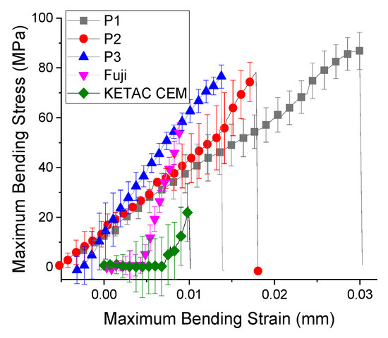
Figure 4.
Flexural strength of biocomposites (mean ± standard deviation).
As shown in Table 6, the maximum stress attained during the flexural test did not vary significantly between the tested samples. The flexural modulus increased from cement P2 to cement P1 only with 10 MPa, while between the cement P2 and cement P3 a slight increase was obtained. The cement P1 fails at a strain of 3%, while the cement P3 fails at 1.5%, under a maximum stress of 86.5 ± 2.50 MPa. The weakest results are attributed to commercial composites Ketac Cem. This material did not had the BisGMA monomer in composition and the maximum stress supported was reduced (26.773 ± 8.55 MPa), with a statistically significant difference between them (p = 2.14195 × 10⁻¹⁷).
Table 6.
Flexural strength evaluation parameters (mean ±standard deviation).
From the analyzed samples, cement P3 presents the highest value of the elasticity modulus (9.8 GPa), having the highest load of filling (50%). As shown in Figure 3, the liner fit of Young’s Modulus of all 3 experimental samples indicated that the ratio between the basic monomer and the dilution one leads to a higher resistance but also to a higher modulus of elasticity. It can be seen that Young’s modulus (Figure 5) is linear with the percentages of fillers, ranging from 7.3 ± 0.8 GPa to 9.6 ± 0.7 GPa. It is higher for the other conventional materials (38.7 ± 1.1 GPa for GC Fuji and 15.977 ± 2.1 GPa for Ketac CEM), with statistical significance difference between them (p = 1.52327 × 10⁻¹⁶). Cement P1, with 30% fillers, has the lowest Young’s modulus (30% fillers) increased flow capacity might provide more contraction stress relaxation and could reduce the marginal microleakage and possible de-bonding [40].
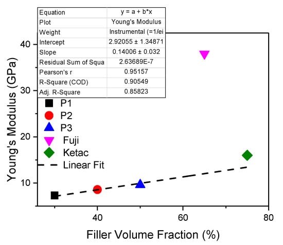
Figure 5.
Young’s Modulus of biocomposites under flexural strength.
3.3. Morphology and Adhesion Test
Figure 6 shows the average values of adhesion determined by 5 measurements, recorded for each biocomposite-metal group. Moreover, the aspect of metallic surface is mentioned (not sandblasted or sandblasted with alumina). Depends on biocomposite type, the bond strengths varied between 5 and 15 MPa. The highest bond strength was recorded for the sample made of cement P3/CoCr sandblasted and the lowest one was obtained for P1/CoCr untreated metallic surfaces. For all SLM substrates, the experimental biocomposites had an exponential increase depending on the percentages of filler.
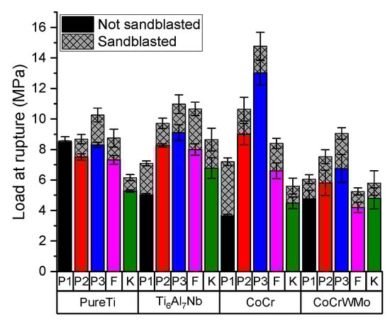
Figure 6.
Bond strength values according to type of biocomposites used and according to type of metal substrate (mean ± standard deviation).
Comparing with untreated metallic surfaces, the adhesion values increased with 0.08 MPa to 3.5 MPa if the metallic SLM surface was sandblasted. Pure Ti is the least influenced substrate both in terms of the sandblasting process and the type of composite applied. Comparing the sandblasted and not sandblasted samples, the statistical analyses for all SLM substrate indicates that there are no significant differences between the groups (p = 0.09376).
After performing the shear bond strength test, the interfaces of the samples were investigated by scanning electron microscopy (SEM). Figure 7 shows SEM images enlarged by ×50 and ×1000 on areas of the plate with remnant material (GC Fuji system), after performing the shear bond strength test. A total detachment of the GC Fuji Plus material is observed, especially in the sandblasted sample. SEM images of surfaces that are not sandblasted showed a uniform, regular and uniform flow. The SEM images of sandblasted surfaces have rough, irregular surfaces, increasing the surface roughness of the SLM substrate.
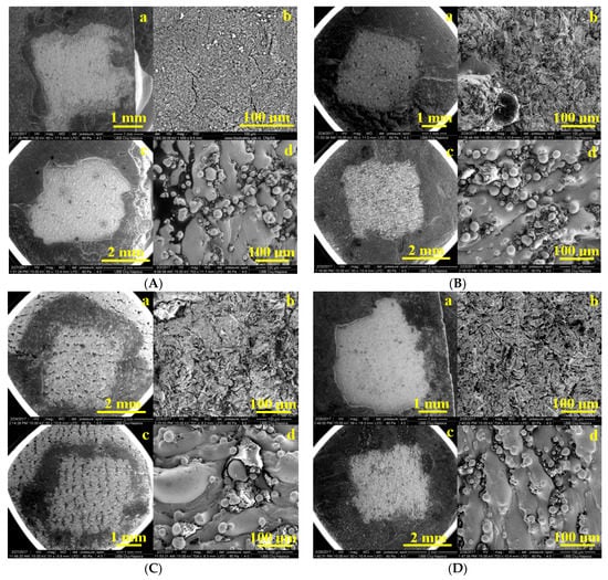
Figure 7.
SEM images enlarged by ×50 and ×1000 on areas of the remnant plate as: (A) PurTi/Fuji (a,b) sandblasted, (c,d) not sandblasted; (B) Ti6Al7Nb/Fuji (a,b) sandblasted, (c,d) not sandblasted; (C) CoCr/Fuji (a,b) sandblasted, (c,d) not sandblasted; (D) CoCrWMo/Fuji (a,b) sandblasted, (c,d) not sandblasted.
The SEM images of the metal samples after the detachment of the experimental bio composites are presented in Figure 8, observing the texture of the remaining materials on the surface of the metal substrate. A glossy film is observed (Figure 8B), with an ordinal thickness of 0.5 µm in which fine particles of cement are incorporated, which has a higher percentage in quartz composites and glass. Thus, Cement P3, having a richer inorganic matrix, could penetrate the cracks on the metal surface, thus enhancing the adhesion between the deposited ceramic system and the CoCr metal.
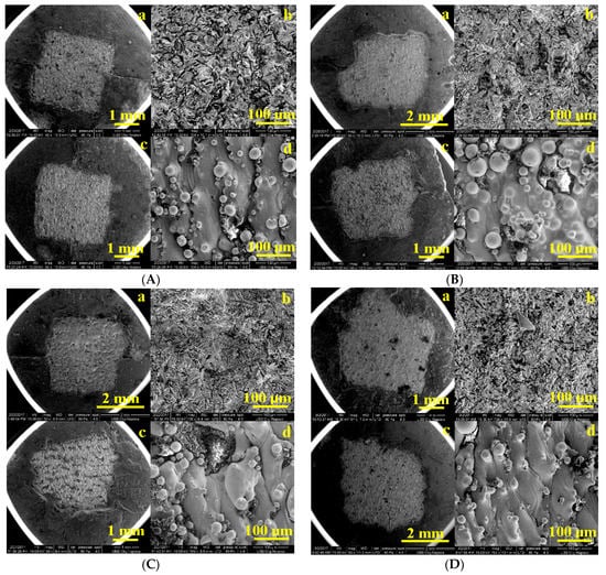
Figure 8.
SEM images enlarged by ×50 and ×1000 on areas of the remnant plate as: (A) PurTi/P2 (a,b) sandblasted, (c,d) not sandblasted; (B) Ti6Al7Nb/P2 (a,b) sandblasted, (c,d) not sandblasted; (C) CoCr/P3 (a,b) sandblasted, (c,d) not sandblasted; (D) CoCrWMo/P3 (a,b) sandblasted, (c,d) not sandblasted.
In the case of the SEM images displaying the sandblasted metallic substrate, a diffusion layer is visible which indicates an interaction between the metal and the applied composites and is uniform on the surface of the treated metal. In the conventional composites/metal fractures, almost no interaction between the metal and the composites was detected, except for a thin, denser layer at the interface.
The sandblasting procedure used in this protocol has the role of fixing the composites to the metal substrate by means of Al2O3. The SEM images in Figure 8 indicate that serious injuries and punctures occurred in groups of metal samples that were not sandblasted (c,d). However, the sandblasted samples showed some minor cracks (a,b). Such results indicate that sandblasting with Al2O3 improved the adhesion of the biocomposites to the metallic substrate. The results obtained suggested that the aluminum oxide particles which remained on the bonding surface after sandblasting were effective at increasing the bond strength [49].
4. Discussion
To obtain the metal substrate SLM process can create specific micro-rough surfaces by modifying the laser parameters which melt the outer boundary contour of specimens. The obtained micro-rough may assist the joining interface but after manufacturing, the SLM surface is always covered by many unmelted particles which can have a significant impact on metal–bicomposite interface. For this reason, the surface roughness and shear bond strength before and after the sandblasting procedure were investigated. Moreover, it was observed that after sandblasting procedure, the value of standard deviation was reduced in all the cases. Practically, this post-processing method helped us to even out the roughness and the quality of the surfaces.
The results obtained are in accordance with the literature [50], where the Ra values for SLM samples are between 5 μm ≤ Ra ≤ 40 μm and depend mainly on SLM processing and powder properties. Increasing roughness values for specimens that have been sandblasted are associated with the existence of additional craters, ridges, and sharp edges of alumina particles. In 2011, Aparicio [51] and Hatamleh [52] reported that after sandblasted procedure the samples proved to have a rougher surface (4.74 μm) compared to those after engraving (1.69 μm). This could be explained by the action of the acid that removes most of the sandblasted material. However, Ra values were lower than those found by us, but this could be attributed to different particle sizes, shape, or hardness of the blasting material [53]. In general, it is assumed that the surface roughness increases with increasing the particle size [54]. Because the CoCr powder had the large particles being between 10 to 65 μm, on this sample we obtain the highest Ra roughness (even after sandblasting).
In the case of the pure Ti substrate, it has the highest stability compared to the biocomposite with which it is coated, Ti implants being recognized in the literature for this feature [55]. As shown in Table 7, the pure Ti substructure obtained by casting manufacturing [28] present lower adhesion values to resin cement even if methods were applied to improve the adhesion process by sandblasting with alumina and application of metal primer (7.5 MPa) or engraved with hydrochloric acid and application of metal primer (6.1 MPa). The shear bond strength of pure Ti adhesion to GC Fuji [29] was approximately the same as the values recorded in this study (8.5 MPa) and compared to resin cement (Panavia and Rely X U200) they increased considerably (17–26 MPa). The same CAD-CAM milling technique was used by Korkmaz [17] to obtain a Ti6Al4V substrate. This alloy is gaining attention thanks to weak solubility of niobium oxide in tissue environment and non-toxicity of oxide layers or soluble ions. Used fiber laser irradiation at 10–20 W method improved the adhesion to polymethyl methacrylate resin (Meliodent Heat Cure) up to 9.7–10.3 MPa. In 2019, Dziaduszewska [42] applied the SLM technique to obtain a Ti13Zr13Nb substrate, which investigated both by sandblasting with alumina and by etched with nitric and hydrofluoric acid, obtaining close but not high adhesion values (7.1–7.2 MPa) with modified polymethyl methacrylate resin.
Table 7.
Comparison regarding the shear bond strength obtained between metallic surfaces and biocomposites.
Different bioresorbable and biodegradable materials were developed to produce implants but there are still reports about the disadvantages of them such as: inflammation, bone resorbtion, and the decrease in mechanical strength [56]. Metallic implants coated with biomaterials play an important role in orthopedic surgery, being in a continuous state of research and development. These implants should be compatible with the human body, have excellent biological and mechanical biocompatibility and, if possible, replicate the functions of the hard tissues [57]. A multitude of studies have focused on researching and solving the disadvantages of implants by introducing biocomposite materials. Previous research has reported the use of several fillers to strengthen alloy structures. Some of these are biodegradable polymer, bioactive glass-ceramics and bioactive composites [58]. The data showed that the presence of these composites on the alloy substrate can lead to a better biocompatibility of the implants; therefore, many studies have addressed the issue of the mechanical properties of biocomposites [58]. The inorganic phase loading varies in the literature from 20% to 80% [59] determining the preparation of three composites with a varied content of 30–40–50% inorganic phase.
The quality of the bond between the two components is directly related to the rigidity of the alloys which prevents the occurrence of flexural forces in the ceramic layer and interface area. Following the adhesion test, the composite layer detached, fracturing and part of it remained on the metallic surface (Figure 8). In the case the Ti surfaces, the highest values were recorded using P3 cement. For the conventional samples, the results of adhesion are either smaller or similar to those of cement P1 (with the smallest amount of filler), even though they have a content of up to 3 times higher the amount of inorganic phase, proving once again that the basic monomer BisGMA offers the best mechanical results. Due to its low modulus of elasticity, it has a high plastic deformation, offering a significant advantage over commercial composites [20].
Since glass-ionomer cements were introduced in the 1970s by Wilson and Kent [60], they have undergone constant performance to keep up with market trends and meet many functional and aesthetic requirements. By increasing the powder/liquid ratio, an attempt was made to increase the relatively small resistance to fracture and wear compared to amalgam and resin composite materials.
It is known from the literature that composites containing based filler Silica (SiO2), which has been used for many applications due to its covalent bonds between atoms, offer excellent chemical stability [61]. New research findings have led to the processing of silicon-based biomaterials in tissue regeneration and drug delivery applications. Vasconcelos [62] tried silica-gel coatings, and Vallet-Regi [63], studied the effect of implant coatings improving the adhesion and the corrosion resistance in simulated body fluid. In the present study, the composite contains the highest amount of SiO2, obtaining the highest adhesions strength.
According to ISO 10477 [64] requirements, the shear bond strength at the interface between biocomposites and substrate should be >5 MPa. In the present study, the CoCrWMo not sandblasted substrate showed mean values lower than 5 MPa in adhesive bonding with Fuji and Ketac (4.3 MPa, 4.5 MPa). Therefore, surface treatment is essential for achieving the desired bond strength, a combination of the entire surface treatment, both mechanical and chemical, produces a stronger and more durable bond between the resin cement and the metal substrate. Therefore, it is essential to apply a surface treatment on SLM substrate to achieve a stronger bond. Also, the chemical composition of biocomposite is a major factor which may improve the adhesion of it on different metallic substrates.
Covering the SLM metallic surfaces with biocomposites offers some advantages, such as limited corrosion, an absence of the release of metal ions which are harmful for the organism, and improved resistance to tearing and fatigue. This aspect motived the present work to develop a biocomposite which can meet the medical requirements and to improve the bond strength between biocomposite and metallic surfaces SLM-manufactured. Moreover, insufficient adhesion strength at biocomposite-metal joint can causes microscopic gaps leading to serious clinical problems. Therefore, it is crucial to establish a strong adhesion.
5. Conclusions
This study was focused on the main mechanical properties; adhesion and morphology of glass ionomer cement biocomposite-metal implants. We used 4 SLM metallic surfaces (pure Ti, Ti6Al7Nb, and CoCr alloys) which were covered with 5 types of biocomposites. The main conclusions from the study are:
- The mechanical and morphological evaluation reveals that the filler content of the composite influences their support to the applied loads. The composite cements with the ratio of 1:1 (organic phase: filling) creates the strongest adhesion on metallic SLM surfaces treated by sandblasting;
- Applying a surface treatment on the SLM substrate (alumina sandblasting) can increase the bond strength with approx. 20%;
- Future studies are needed to investigate the impact of the present biocomposite-metallic structures on osteointegration behavior, stress shielding effect, and bone fixation.
Author Contributions
Conceptualization, M.M. and D.L.; methodology, A.B., C.C. and S.C.; validation, D.P.; formal analysis, M.R.; investigation, S.C., C.C., D.P., A.B. and R.E.; data curation, S.C. and D.L.; writing—original draft preparation S.C.; writing—review and editing, N.B. and C.C.; supervision, M.M. All authors have read and agreed to the published version of the manuscript.
Funding
This research received no external funding.
Institutional Review Board Statement
Not applicable.
Informed Consent Statement
Not applicable.
Data Availability Statement
The data that support the findings of this study are available from the corresponding author upon reasonable request.
Acknowledgments
This work was sustained by the Romanian Ministry of Education and Research, Project nr. 334PED/2020.
Conflicts of Interest
The authors declare no conflict of interest. The funders had no role in the design of the study; in the collection, analyses, or interpretation of data; in the writing of the manuscript, or in the decision to publish the results.
References
- Puleo, D.; Nanci, A. Understanding and controlling the bone-implant interface. Biomaterials 1999, 20, 2311–2321. [Google Scholar] [CrossRef]
- Souza, J.C.M.; Henriques, M.; Teughels, W.; Ponthiaux, P.; Celis, J.-P.; Rocha, L.A. Wear and Corrosion Interactions on Titanium in Oral Environment: Literature Review. J. Bio-Tribo-Corros. 2015, 1, 13. [Google Scholar] [CrossRef]
- Saptaji, K.; Gebremariam, M.A.; Azhari, M.A.B.M. Machining of biocompatible materials: A review. Int. J. Adv. Manuf. Technol. 2018, 97, 2255–2292. [Google Scholar] [CrossRef]
- Mugal, P.M.; Farooq, U.M.; Mumtaz, J.; Mia, M.; Shareef, M.; Javed, M.; Jamil, M.; Pruncu, C.I. Surface modification for os-seointegration of Ti6Al4V Eli using powder sinking EDM. J. Mechan. Behav. Biomed. Mater. 2021, 113, 104145. [Google Scholar] [CrossRef]
- Xing, G.; Manon, F.; Guillaume, H. Biomechanical behavior of bone-implant interface: A review. J. R. Soc. Interf. 2019, 16. [Google Scholar] [CrossRef]
- Park, J.W.; Kim, H.J.; An, C.H.; Hanawa, T. Enhanced osteoconductivity of micro-structured titanium implants (XiVE S CELLplus) by addition of surface calcium chemistry: A histomorphometric study in the rabbit femur. Clin. Oral Implant. Res. 2009, 20, 684–690. [Google Scholar] [CrossRef]
- Opoz, T.T.; Yasar, H.; Ekmekci, N.; Ekmekci, B. Particle migration and surface modification on Ti6Al4V in SiC powder mixed electrical discharge machining. J. Manuf. Process. 2018, 31, 744–758. [Google Scholar] [CrossRef]
- Liu, F.; Ran, Q.; Zhao, M.; Zhang, T.; Zhang, D.Z.; Su, Z. Additively manufactured continuous cell-size gradient porous scaffolds: Pore characteristics, mechanical properties and biological responses in vitro. Materials 2020, 13, 2589. [Google Scholar] [CrossRef]
- Ganbold, B.; Heo, S.J.; Koak, J.Y.; Kim, S.K.; Cho, J. Human Stem Cell Responses and Surface Characteristics of 3D Printing Co-Cr Dental Material. Materials 2019, 12, 3419. [Google Scholar] [CrossRef] [PubMed]
- Nica, M.; Cretu, B.; Ene, D.; Antoniac, I.; Gheorghita, D.; Ene, R. Failure Analysis of Retrieved Osteosynthesis Implants. Materials 2020, 13, 1201. [Google Scholar] [CrossRef]
- AlMangour, B.; Yang, J.M. Improving the surface quality and mechanical properties by shot-peening of 17-4 stainless steel fabricated by additive manufacturing. Mater. Des. 2016, 110, 914–924. [Google Scholar] [CrossRef]
- Maamoun, A.H.; Elbestawi, M.A.; Veldhuis, S.C. Influence of shot peening on AlSi10Mg Parts fabricated by additive manufacturing. J. Manuf. Mater. Process. 2018, 2, 40. [Google Scholar] [CrossRef]
- Fiore, A.; Savio, G.; Stellini, E.; Vigolo, P.; Monaco, C.; Meneghello, R. Influence of ceramic firing on marginal gap accuracy and metal-ceramic bond strength of 3D-printed Co-Cr frameworks. J. Prosthet. Dent. 2020, 124, 75–80. [Google Scholar] [CrossRef]
- Xia, R.Z.; Zhai, Z.J.; Chang, Y.Y.; Li, H.W. Clinical applications of 3-dimensional printing technology in hip joint. Orthoped. Surg. 2019, 11, 533–544. [Google Scholar] [CrossRef] [PubMed]
- Murr, L.E. Metallurgy principles applied to powder bed fusion 3D printing/additive manufacturing of personalized and optimized metal and alloy biomedical implants: An overview. J. Mater. Res. Technol. 2020, 9, 1087–1103. [Google Scholar] [CrossRef]
- Cirstoiu, C.; Ene, R.; Panti, Z.; Ene, P.; Cirstoiu, M. Particularities of shoulder recovery after arthroscopic bankart repair with bioabsorbable and metallic suture anchors. Mater. Plast. 2015, 52, 361–363. [Google Scholar]
- Das, S.; Dholam, K.; Gurav, S.; Bendale, K.; Ingle, A.; Mohanty, B.; Chaudhari, P.; Bellare, J.R. Accentuated osseointegration in osteogenic nanofibrous coated titanium implants. Nature Sci. Rep. 2019, 9, 17638. [Google Scholar] [CrossRef] [PubMed]
- Korkmaz, F.M.; Aycan, S. Effect of fiber laser irradiation on the shear bond strength between acrylic resin and titanium. Scanning 2019, 5452919. [Google Scholar] [CrossRef]
- Lietaert, K.; Cutolo, A.; Boey, D.; Van Hooreweder, B. Fatigue life of additively manufactured Ti6Al4V scaffolds under tension-tension, tension-compression and compression-compression fatigue load. Nat. Sci. Rep. 2018, 8, 4957. [Google Scholar] [CrossRef] [PubMed]
- Wood, M.M.; Warshaw, E.M. Hypersensitivity reactions to titanium: Diagnosis and management. Dermatitis 2015, 26, 7–25. [Google Scholar] [CrossRef] [PubMed]
- Jiman, P.; Moldovan, M.; Sarosi, C.; Muntean, A.; Pop, A.S.; Tarmure, V.; Popa, C.; Mohan, A.G. Surface characterization and cytotoxicity analysis of the titanium alloys for dentistry. Stud. Univ. Babes-Bolyai Chem. 2020, 65, 149–162. [Google Scholar] [CrossRef]
- McGinley, E.L.; Moran, G.P.; Fleming, G.J. Biocompatibility effects of indirect exposure of base-metal dental casting alloys to a human-derived three-dimensional oral mucosal model. J. Dent. 2013, 41, 1091–1100. [Google Scholar] [CrossRef] [PubMed]
- Papadogiannis, D.; Dimitriadi, M.; Zafiropoulou, M.; Gaintantzopoulou, M.D.; Eliades, G. Reactivity and bond strength of universal dental adhesives with Co-Cr alloy and zirconia. Dent. J. 2019, 7, 78. [Google Scholar] [CrossRef]
- Yoldan, E.E.; Türker, N.; Büyükkaplan, U.Ş.; Ozarslan, M.M.; Karali, R.; Deniz, A.T. Evaluation of the bond strengths between dental porcelain and cobalt-chromium metal frameworks manufactured with different techniques after the thermal aging process. Scanning 2020, 9315236. [Google Scholar] [CrossRef]
- Li, J.; Chen, C.; Liao, J.; Liu, L.; Ye, X.; Lin, S.; Ye, J. Bond strengths of porcelain to cobalt-chromium alloys made by casting, milling, and selective laser melting. J. Prost. Dent. 2017, 118, 69–75. [Google Scholar] [CrossRef]
- Almilhatti, H.J.; Neppelenbroek, K.H.; Vergani, C.E.; Machado, A.L.; Pavarina, A.C.; Giampaolo, E.T. Adhesive bonding of resin composite to various titanium surfaces using different metal conditioners and a surface modification system. J. Appl. Oral Sci. 2013, 21, 590–596. [Google Scholar] [CrossRef]
- Jurel, S.K.; Mishra, N.; Chand, P.; Aggarwal, H.; Singh, R.D.; Singh, B.P. Comparison of the effectiveness of Tokuyama and GC II metal primer on the bond strength of acrylic resins to Ti-6Al-7Nb. Natl. J. Maxillofac. Surg. 2017, 8, 125–129. [Google Scholar] [CrossRef]
- Veljee, T.M.; Shruthi, C.S.; Poojya, R. Evaluation and comparison of the effect of different surface treatment modifications on the shear bond strength of a resin cement to titanium: An in vitro study. J. Indian Prosthodont. Soc. 2015, 15, 308–312. [Google Scholar] [CrossRef]
- Nakhaei, M.; Fendereski, Z.; Alavi, S.; Mohammadipour, H.S. The Micro-Shear bond strength of different cements to commercially pure titanium. J. Clin. Exp. Dent. 2019, 11, 820–828. [Google Scholar] [CrossRef]
- Lencioni, K.A.; Menani, L.R.; Macedo, A.P.; Ribeiro, R.F.; Pereirade Almeida, R. Tensile bond strength of cast commercially pure titanium dowel and cores cemented with three luting agents. J. Prost. Res. 2010, 54, 164–167. [Google Scholar] [CrossRef] [PubMed]
- ASTM F67-13, Standard Specification for Unalloyed Titanium, for Surgical Implant Applications (UNS R50250, UNS R50400, UNS R50550, UNS R50700); ASTM International: West Conshohocken, PA, USA, 2017.
- ISO 22674: 2016: Dentistry—Metallic Materials for Fixed and Removable Restorations and Appliances; International Organization for Standardization: Geneva, Switzerland, 2016.
- ASTM F75-18, Standard Specification for Cobalt-28 Chromium-6 Molybdenum Alloy Castings and Casting Alloy for Surgical Implants (UNS R30075); ASTM International: West Conshohocken, PA, USA, 2018.
- Cosma, C.; Drstvensek, I.; Berce, P.; Prunean, S.; Legutko, S.; Popa, C.; Balc, N. Physical–mechanical characteristics and microstructure of Ti6Al7Nb lattice structures manufactured by selective laser melting. Materials 2020, 13, 4123. [Google Scholar] [CrossRef] [PubMed]
- Burde, A.V.; Cuc, S.; Radu, A.; Rusu, M.A.; Cosma, C.S.; Leordean, D. Microstructural analysis of the interface between some superalloys and composite/ceramic materials. Stud. Univ. Babes-Bolyai Chem. 2016, LXI, 205–214. [Google Scholar]
- Nishigawa, G.; Maruo, Y.; Irie, M.; Maeda, N.; Yoshihara, K.; Nagaoka, N.; Matsumoto, T.; Minagi, S. Various effects of sandblasting of dental restorative materials. PLoS ONE 2016, 11, e0147077. [Google Scholar] [CrossRef]
- Kern, M.; Thompson, V.P. Sandblasting and silica-coating of dental alloys: Volume loss, morphology and changes in the surface composition. Dent. Mater. 1993, 9, 151–161. [Google Scholar] [CrossRef]
- ISO 4287:1997 Geometrical Product Specifications (GPS)—Surface Texture: Profile Method—Terms, Definitions and Surface Texture Parameters; International Organization for Standardization: Geneva, Switzerland, 1997.
- Meyers, M.A.; Chen, P.Y.; Lin, A.Y.M.; Seki, Y. Biological materials: Structure and mechanical properties. Prog. Mater. Sci. 2008, 53, 1–206. [Google Scholar] [CrossRef]
- Sabbagh, J.; Vreven, J.; Leloup, G. Dynamic and static moduli of elasticity of resin-based materials. Dent. Mater. 2002, 18, 64–71. [Google Scholar] [CrossRef]
- ISO 4049:2000 Denstistry—Polymer—Based Filling, Restorative and Luting Materials; International Organization for Standardization: Geneva, Switzerland, 2000.
- Dziaduszewska, M.; Wekwejt, M.; Bartmański, M.; Pałubicka, A.; Gajowiec, G.; Seramak, T.; Osyczka, A.M.; Zieliński, A. The effect of surface modification of Ti13Zr13Nb alloy on adhesion of antibiotic and nanosilver-loaded bone cement coatings dedicated for application as spacers. Materials 2019, 12, 2964. [Google Scholar] [CrossRef]
- Lu, Y.; Wu, S.; Gan, Y.; Li, J.; Zhao, C.; Zhuo, D.; Lin, J. Investigation on the microstructure, mechanical property and corrosion behavior of the selective laser melted CoCrW alloy for dental application. Mater. Sci. Eng. C Mater. Biol. Appl. 2015, 49, 517–525. [Google Scholar] [CrossRef]
- Barriobero-Vila, P.; Gussone, J.; Stark, A.; Schell, N.; Haubrich, J.; Requena, G. Peritectic titanium alloys for 3D printing. Nat. Commun. 2018, 9, 3426. [Google Scholar] [CrossRef]
- Xu, C.; Sikan, F.; Atabay, S.E.; Muñiz-Lerma, J.A.; Sanchez-Mata, O.; Wang, X.; Brochu, M. Microstructure and mechanical behavior of as-built and heat-treated Ti–6Al–7Nb produced by laser powder bed fusion. Mater. Sci. Eng. A 2020, 793, 139978. [Google Scholar] [CrossRef]
- Bernevig-Sava, M.A.; Stamate, C.; Lohan, N.M.; Baciu, A.M.; Postolache, I.; Baciu, C.; Baciu, E.R. Considerations on the surface roughness of SLM processed metal parts and the effects of subsequent sandblasting. IOP Conf. Ser. Mater. Sci. Eng. 2019, 572, 012071. [Google Scholar] [CrossRef]
- Kern, M.; Thompson, V.P. Durability of resin bonds to a cobalt-chromium alloy. J Dent. 1995, 23, 47–54. [Google Scholar] [CrossRef]
- Tulga, A. Shear bond strength of veneer composite to cobalt-chromium alloys fabricated differently. Süleyman Demirel Univ. Sağlık Bilimleri Derg. 2018, 9, 34–39. [Google Scholar] [CrossRef][Green Version]
- O’Brien, W.J. Structure and properties of metals and alloys, Dental Materials and Their Selection, 4th ed.; Quintessence Publishing Co., Inc.: Michigan, Washtenaw, 2008; pp. 168–179. [Google Scholar]
- Vayssette, B.; Saintier, N.; Brugger, C.; Elmay, M.; Pessard, E. Surface roughness of Ti-6Al-4V parts obtained by SLM and EBM: Effect on the high cycle fatigue life. Procedia 2018, 213, 89–97. [Google Scholar] [CrossRef]
- Aparicio, C.; Padrós, A.; Gil, F.J. In vivo evaluation of micro-rough and bioactive titanium dental implants using histometry and pull-out tests. J. Mech. Behav. Biomed. Mater. 2011, 4, 1672–1682. [Google Scholar] [CrossRef]
- Hatamleh, M.M.; Wu, X.; Alnazzawi, A.; Watson, J.; Watts, D. Surface characteristics and biocompatibility of cranioplasty titanium implants following different surface treatments. Dent. Mater. 2018, 34, 676–683. [Google Scholar] [CrossRef]
- Al-Radha, A.S.D. The impact of different acids etch on sandblasted titanium dental implant surfaces topography. J. Dent. Med. Sci. 2016, 15, 83–86. [Google Scholar] [CrossRef]
- Manjaiah, M.; Laubscher, R.F. A review of the surface modifications of titanium alloys for biomedical applications. Mater. Technol. 2017, 51, 181–190. [Google Scholar] [CrossRef]
- Priyadarshini, B.; Rama, M.; Vijayalakshmi, U. Bioactive coating as a surface modification technique for biocompatible metallic implants: A review. J. Asian Ceram. Soc. 2019, 7, 397–406. [Google Scholar] [CrossRef]
- Prakasam, M.; Locs, J.; Salma-Ancane, K.; Loca, D.; Largeteau, A.; Berzina-Cimdina, L. Biodegradable materials and metallic implants—A Review. J. Funct. Biomater. 2017, 8, 44. [Google Scholar] [CrossRef]
- Niinomi, M. Design and development of metallic biomaterials with biological and mechanical biocompatibility. J. Biomed. Mater. Res. A 2019, 107, 944–954. [Google Scholar] [CrossRef] [PubMed]
- Wang, J.F.; Liu, X.Y.; Luan, B. Fabrication of Ti/polymer biocomposites for load-bearing implant applications. J. Mater. Process. Technol. 2008, 197, 428–433. [Google Scholar] [CrossRef]
- Dorozhkin, S.V. Biocomposites and hybrid biomaterials based on calcium orthophosphates. Biomatter 2011, 1, 3–56. [Google Scholar] [CrossRef]
- Wilson, A.D.; Kent, B.E. A new translucent cement for dentistry. The glass ionomer cement. Br. Dent. J. 1972, 132, 133–135. [Google Scholar] [CrossRef] [PubMed]
- Lee, D.W.; Yoo, B.R. Advanced silica/polymer composites: Materials and applications. J. Ind. Eng. Chem. 2016, 38, 1–12. [Google Scholar] [CrossRef]
- Vasconcelos, D.D.L.; Carvalho, J.A.N.; Mantel, M.; Vasconcelos, W.L. Corrosion resistance of stainless steel coated with sol-gel silica. J. Non-Cryst. Solids 2000, 273, 135–139. [Google Scholar] [CrossRef]
- Vallet-Regi, M. Ceramics for medical applications. J. Chem. Soc. Dalton Trans. 2001, 2, 97–108. [Google Scholar] [CrossRef]
- ISO 10477:2004 Dentistry-Polymer-Based Crown and Bridge Materials; International Organization for Standardization: Geneva, Switzerland, 2004.
Publisher’s Note: MDPI stays neutral with regard to jurisdictional claims in published maps and institutional affiliations. |
© 2021 by the authors. Licensee MDPI, Basel, Switzerland. This article is an open access article distributed under the terms and conditions of the Creative Commons Attribution (CC BY) license (https://creativecommons.org/licenses/by/4.0/).