3.1. Characterization of the Surface-Modified Region
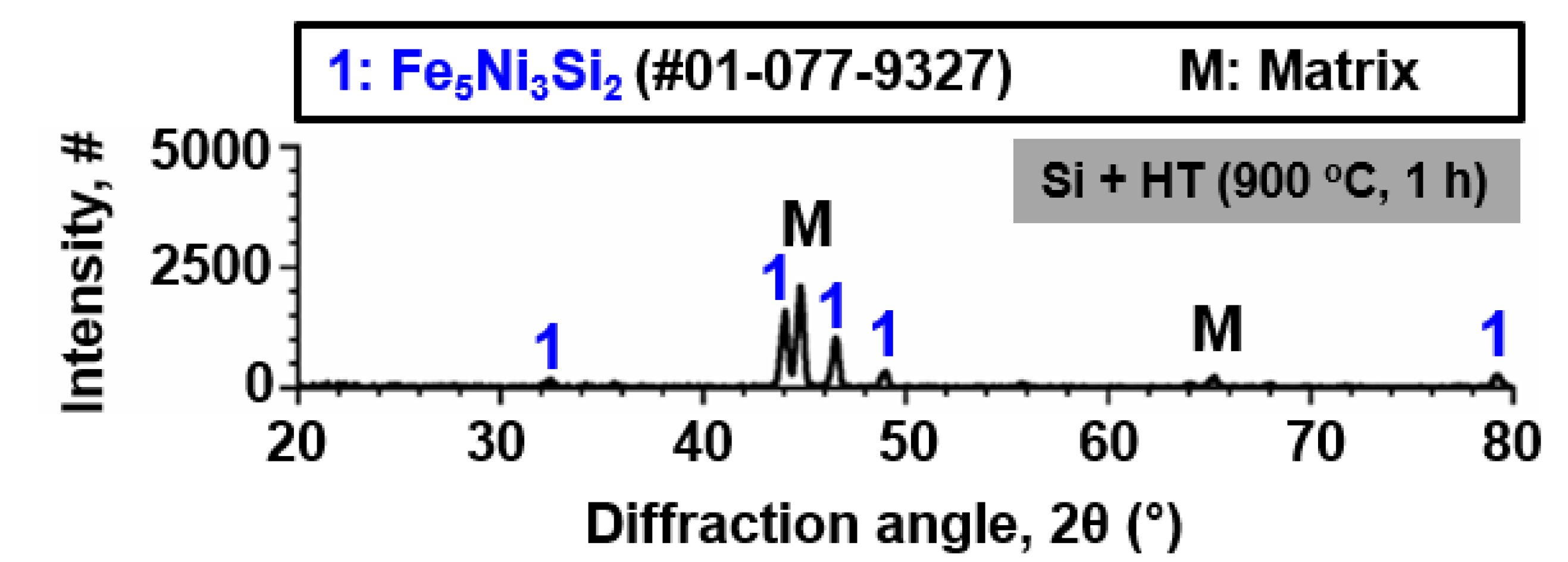
Figure 1 shows the results of XRD analysis on SS 316LN after Si deposition and IDHT (900 °C, 1 h). Other than the peaks from the matrix, peaks of Fe
5Ni
3Si
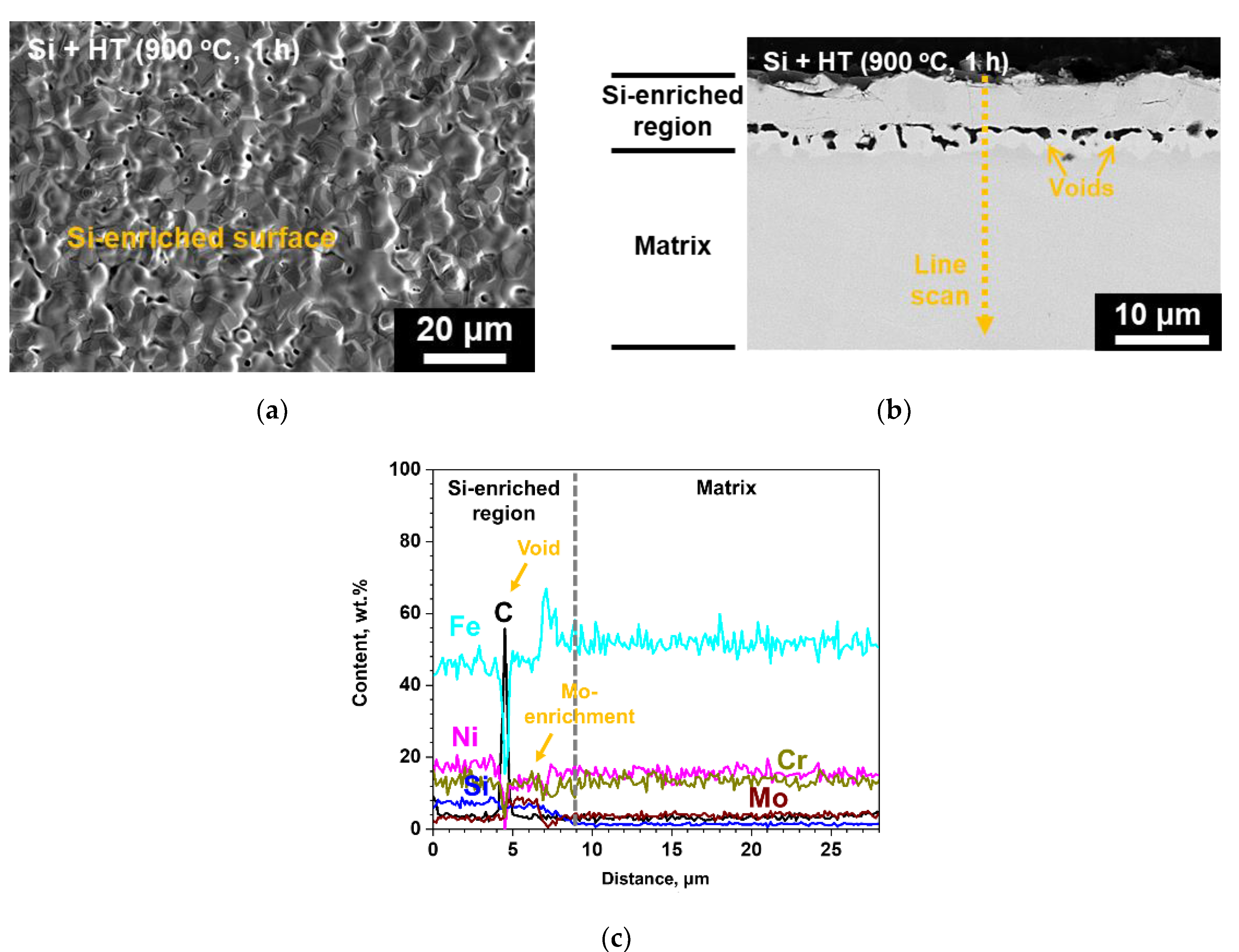
2 silicide phase were detected. Surface SEM micrograph shows that a continuous surface layer with somewhat blocky morphology was formed (
Figure 2a). Cross-sectional backscattered electron (BSE) micrograph of the specimen is shown in
Figure 2b. A surface layer with different contrast from the adjacent matrix can be identified. This region would correspond to Fe
5Ni
3Si
2 silicide phase detected by XRD analysis.
Figure 2c shows the result of EDS line scanning along the dotted arrow indicated in the BSE micrograph. The surface region is enriched in Si about 10 wt.% and about 9 μm in thickness. In addition, Fe, Ni, and Cr contents in this layer are about 45, 18, and 14 wt.%, respectively. This indicates that interdiffusion of the deposited Si layer and elements in the matrix occurred during heat treatment at 900 °C, and formed Fe
5Ni
3Si
2 phase. Previously, Zhang et al. evaluated the phase equilibria of Fe-Ni-Si system at 850 °C and confirmed Fe
5Ni
3Si
2 phase as thermodynamically stable phase in Fe and Ni composition ranges of 46.5–56.3 at.% and 23.6–32.5 at.%, respectively [
8].
Meanwhile, discontinuous voids were observed in the Si-enriched layer. High C region in EDS line scan result (
Figure 2c) corresponds to the void, as the voids were filled by C-rich resin during sample mounting for cross-sectional analyses. These voids would have formed during heat treatment due to faster outward diffusion of matrix elements toward the Si coating layer. Perez et al. also reported formation of voids on Si diffusion-coated SS 304 at the coating/alloy interface [
9]. Such Kirkendall voids may be avoided by optimization of heat treatment temperature. On the other hand, relative enrichment of Mo was noted adjacent to the voids (
Figure 2c). The change in chemical compositions due to Si-enrichment at the surface during heat treatment would result in activity changes, which in turn would have resulted in Mo diffusion from the underlying matrix toward the coating/matrix interface. This is indicated by depletion of Mo below the region of Mo-enrichment shown in EDS line scan result (
Figure 2c).
3.2. Weight Changes after Corrosion Tests in S-CO2 and Steam
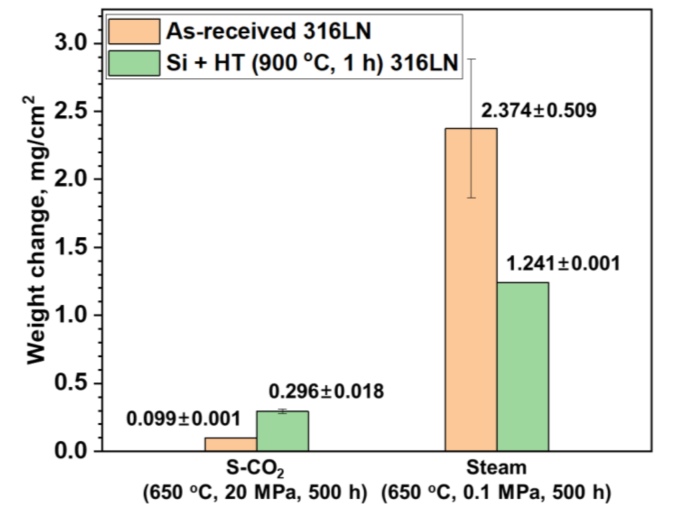
Weight changes of the as-received and surface-modified SS 316LN after exposure to S-CO
2 (650 °C, 20 MPa, 500 h) and steam (650 °C, 0.1 MPa, 500 h) environments are shown in
Figure 3. The average weight change values of the two specimens of each condition are also listed in the figure. As shown in the figure, weight gain in S-CO
2 environment is lower for the as-received condition than that of the surface-modified specimen. However, it should be mentioned that reported weight change values of the as-received SS 316LN can vary in high temperature S-CO
2 environments under same conditions due to oxide spallation. For example, in a previous study, it was reported that the as-received SS 316LN showed weight gain of 0.44 mg/cm
2 after exposure to S-CO
2 at 650 °C (20 MPa) for 500 h [
5]. Still, another study reported weight gain of about 0.1 mg/cm
2 for the as-received SS 316LN corroded in the same condition [
10]. In this study, the as-received SS 316LN had weight gain of 0.099 mg/cm
2. Such discrepancies in weight change values of as-received SS 316LN tested in similar conditions can be ascribed to different times at which oxide spallation and subsequent Fe-rich oxide formation occurs on 316LN in high temperature environments above 600 °C. In this regard, the small variance between the weight change values of the two as-received samples in this study would be coincidental. To the contrary, as will be shown in the next section, oxide spallation was not observed for the surface-modified SS 316LN after S-CO
2 exposure. Thus, the weight change comparisons between the as-received and surface-modified conditions after S-CO
2 corrosion may not be an accurate representation of the actual corrosion resistances.
In the case of specimens exposed to steam environment, weight gains of the surface-modified specimen is about half that of the as-received specimen. It is notable that weight gains are significantly greater for steam-exposed specimens compared to those exposed to S-CO
2. It has been reported that high pressure of S-CO
2 results in greater corrosion rates compared to atmospheric pressure CO
2 [
11]. However, even with higher pressure of S-CO
2 of 20 MPa, steam at atmospheric pressure resulted in greater oxidation. It has been suggested that hydrogen would be generated by oxidation in steam [
12]. The hydrogen as proton ions would permeate into the oxide and change its structure and oxidation behavior. Kim et al. compared the corrosion characteristics of Ni-base alloys in steam at 900 °C with and without hydrogen addition, and found that corrosion rates were greater in hydrogen-added steam [
7]. On the other hand, hydrogen would not be produced in S-CO
2 environment, which may be a factor in lower weight gains in S-CO
2 compared to that in steam.
3.3. Characterization of Oxides Formed in High Temperature S-CO2
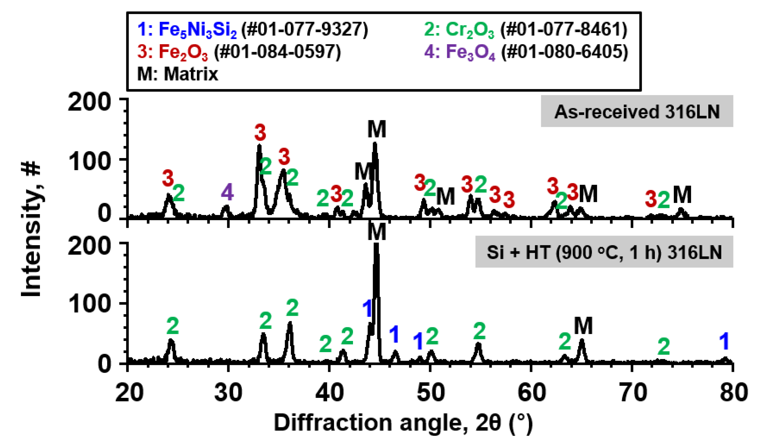
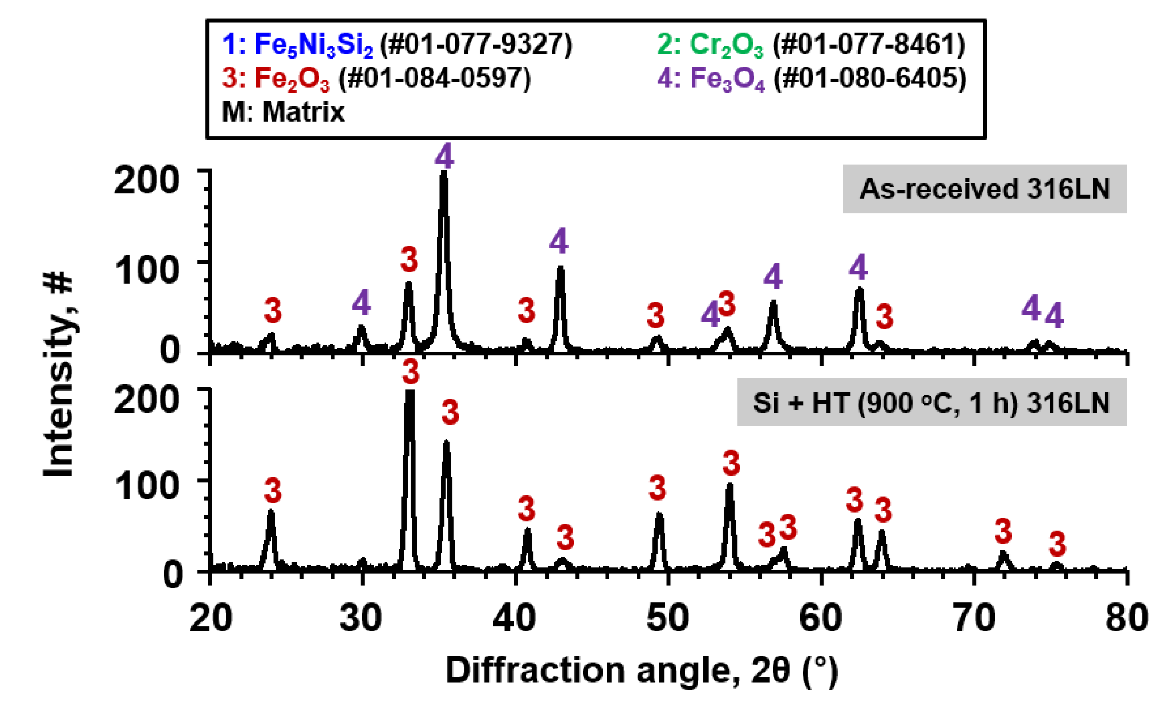
Figure 4 shows the results of XRD analysis of the as-received and surface-modified SS 316LN after exposure in S-CO
2 at 650 °C (20 MPa) for 500 h. For the as-received SS 316LN, peaks of chromia (Cr
2O
3) and Fe-rich oxides (mainly Fe
2O
3) were found. For the surface-modified specimen, chromia peaks were detected, along with peaks of Fe
5Ni
3Si
2 phase and matrix that were observed before corrosion test (
Figure 1).
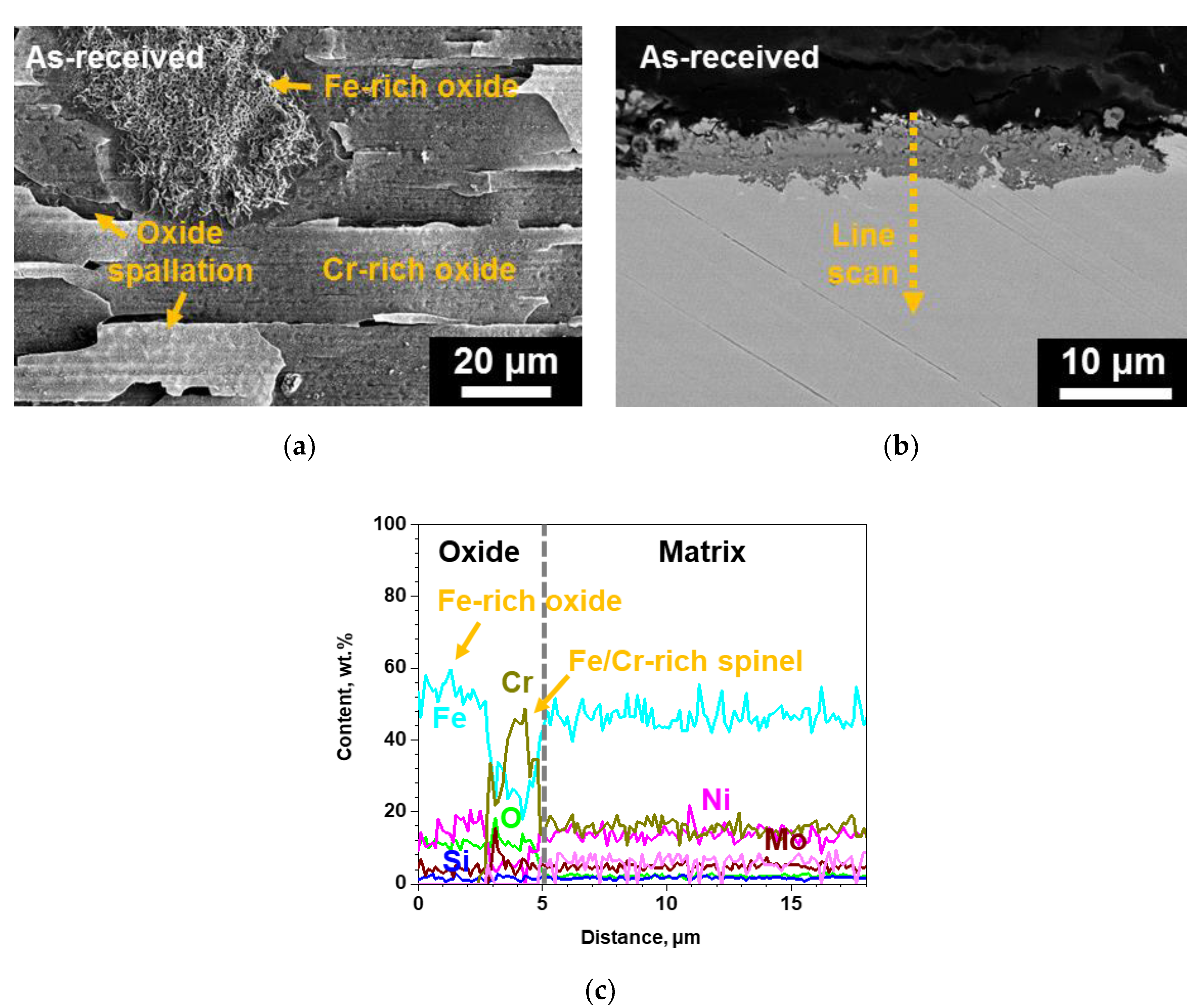
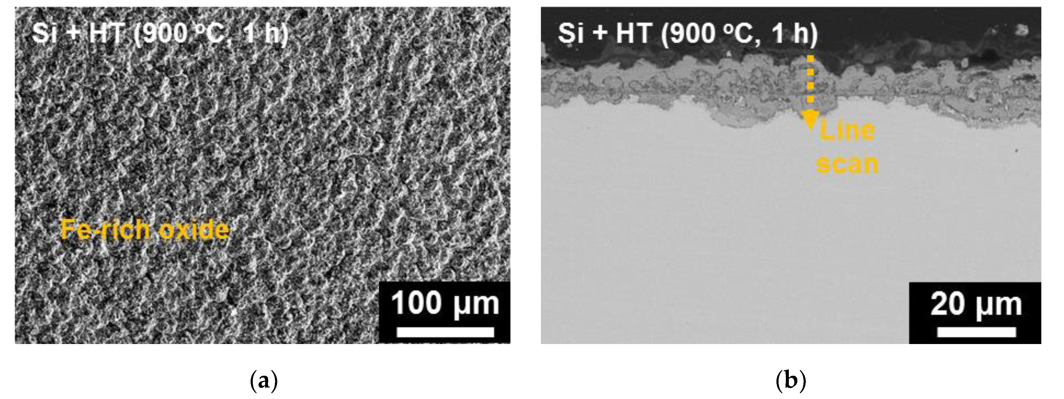
Figure 5a shows the plan-view SEM micrograph of the oxides formed on the as-received SS 316LN after S-CO
2 exposure. Severe spallation of a thin oxide layer and formation of thick oxides can be noted. EDS analysis (not shown) confirmed that the thin oxide layer was mainly rich in Cr while the thick oxide was rich in Fe, which is in agreement with previous studies [
1,
2]. Cross-sectional backscattered electron (BSE) micrograph of this specimen is shown in
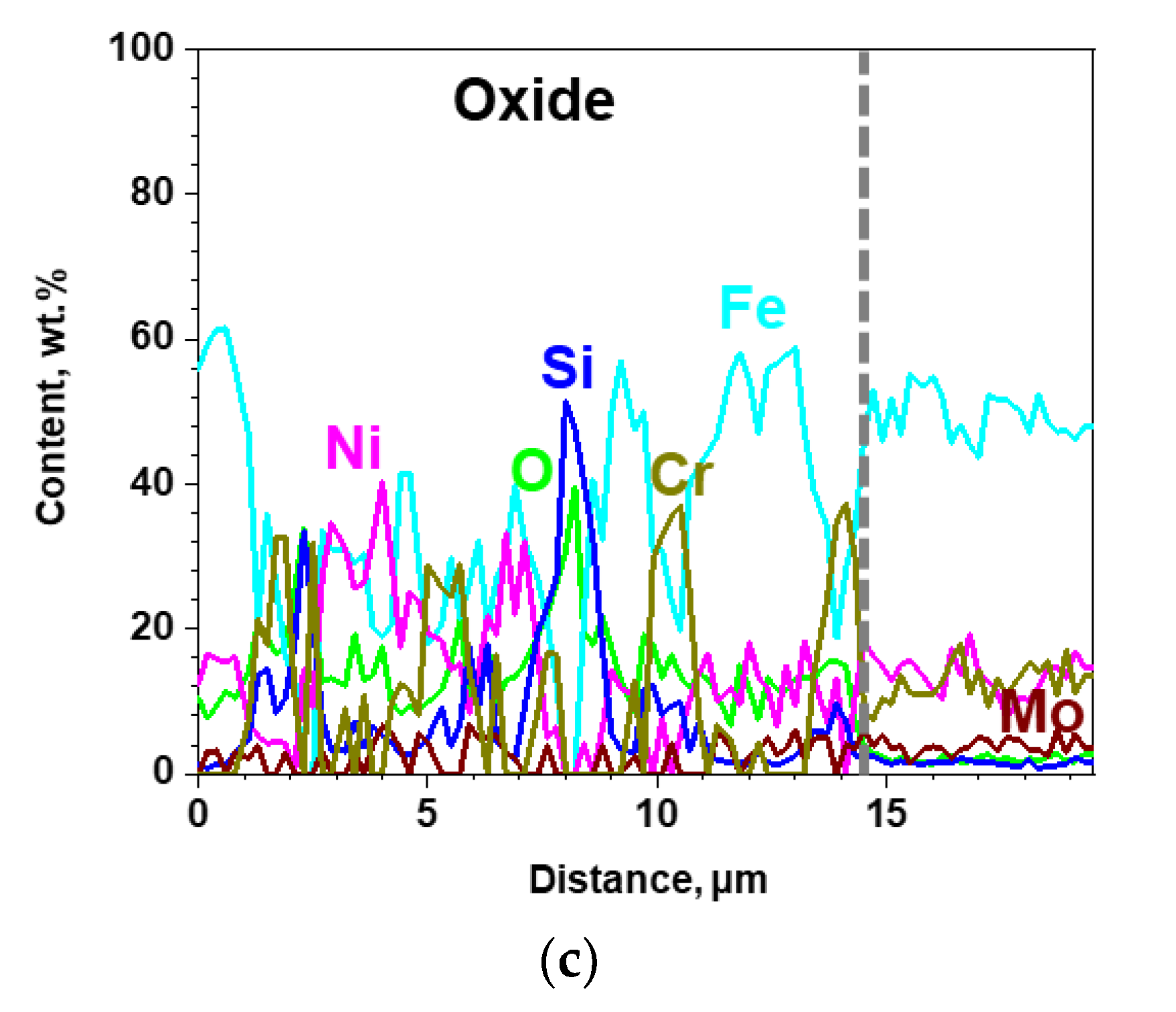
Figure 5b. The Cr-rich oxide layer was difficult to find due to spallation, while thick Fe-rich oxide region was seen. EDS line scan results indicated that this oxide was about 5 μm in thickness, while it consisted of a duplex structure with outer oxide being Fe-rich and inner oxide being rich in both Fe and Cr (
Figure 5c). Such oxides would have formed because of depletion of Cr in the underlying matrix after oxide spallation.
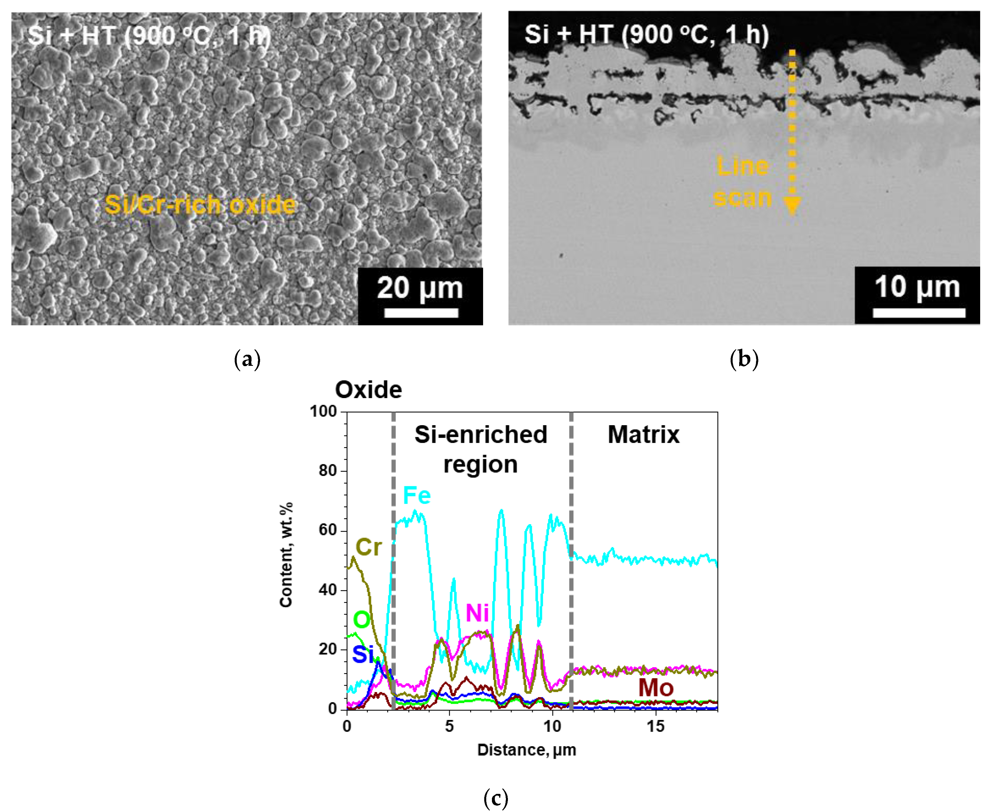
In the case of the surface-modified specimen, a continuous oxide could be observed in the surface SEM micrograph, while oxide spallation was not observed (
Figure 6a). In addition, the oxides have a blocky and nodular morphology, similar to that of the surface of the surface-modified specimen before corrosion test shown in
Figure 2a. This suggests that the oxide formed on the surface-modified specimen is rather thin. From cross-sectional BSE micrograph and EDS line scanning (
Figure 6b,c), it was observed that the oxide had a thickness of about 2 μm and was rich mainly in Cr and Si. Thus, from the thin adherent oxide formed on the surface-modified SS 316LN in contrast to spalled Cr-rich oxides and locally thick Fe-rich oxides formed on the as-received SS 316LN, it is quite clear that corrosion resistance of the surface-modified SS 316LN is better than the as-received SS 316LN in S-CO
2.
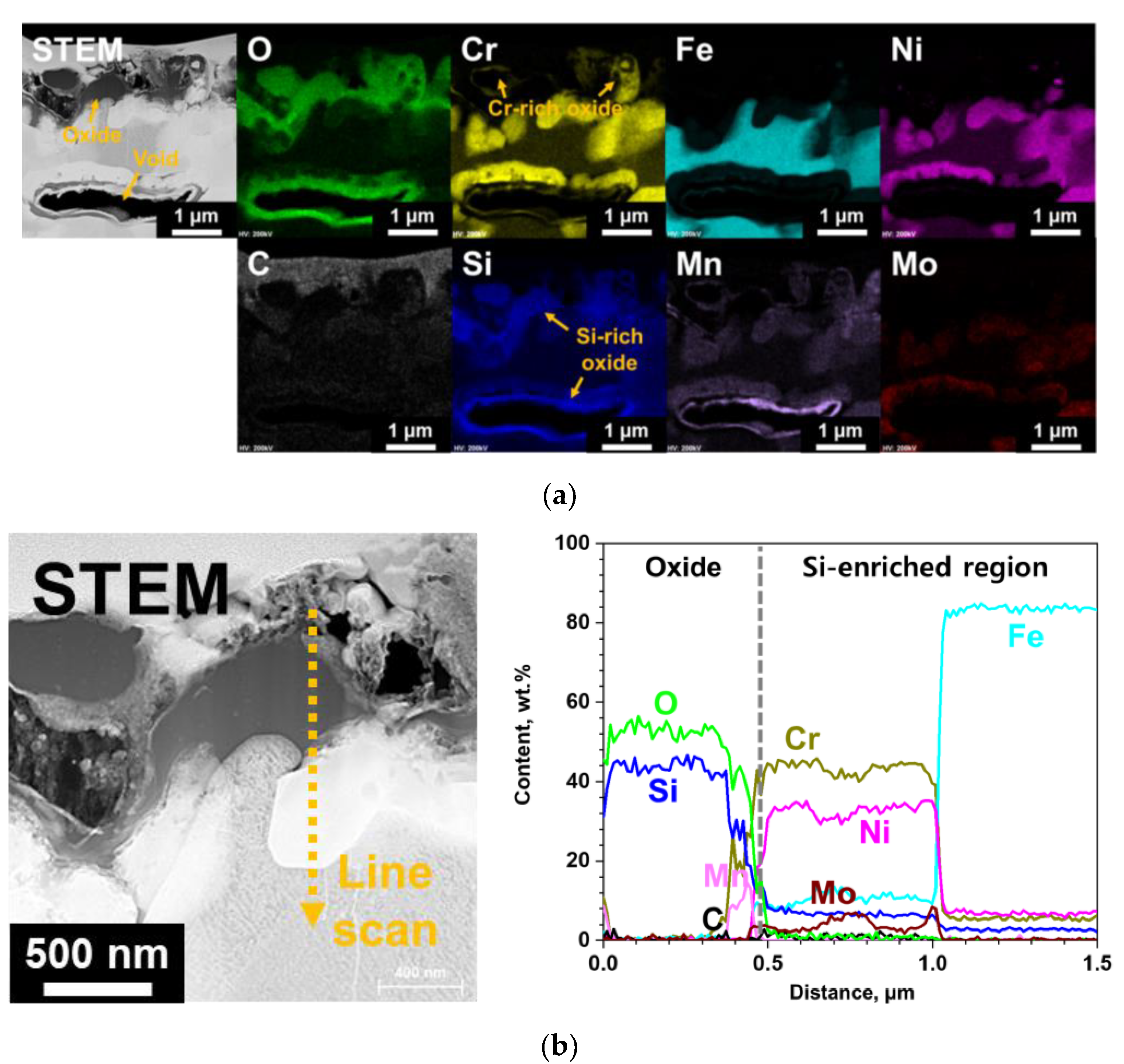
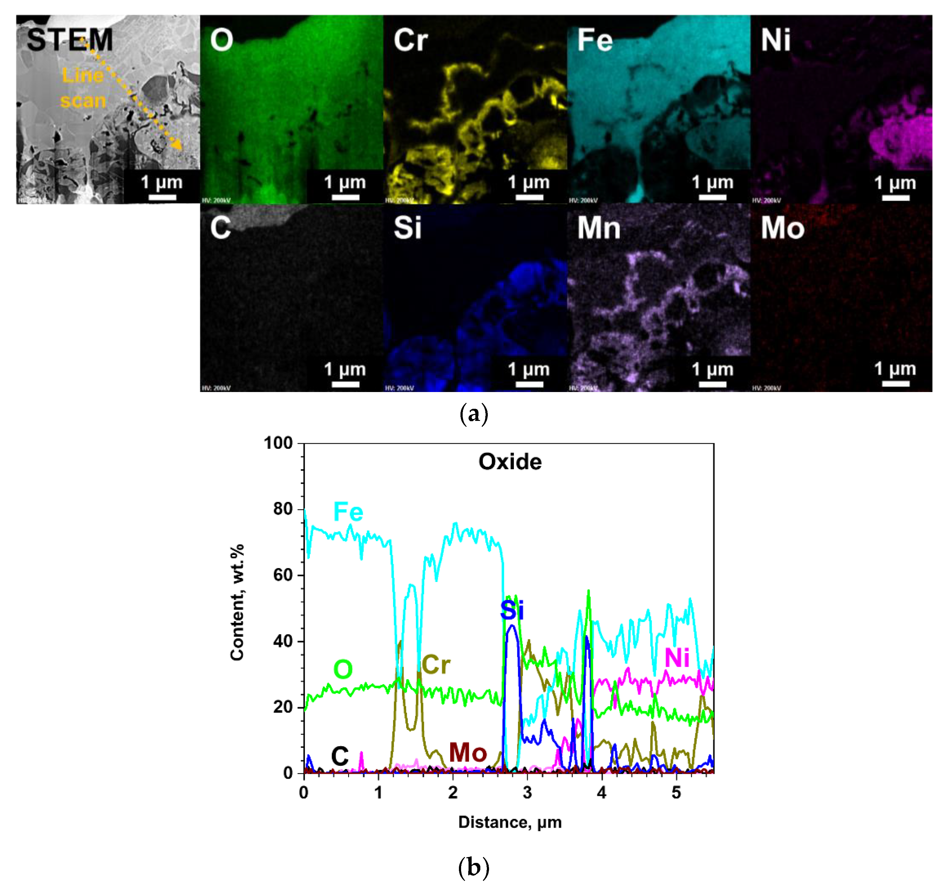
TEM analyses results of the oxide layer formed on the surface-modified specimen after S-CO
2 exposure are shown in
Figure 7. The oxide is mainly rich in Si, while some discontinuous Cr-rich oxides can also be observed. It is interesting to note that Si-rich oxides were not observed in XRD analysis results, while only chromia peaks were found (
Figure 4). This would be due to the amorphous nature of the Si-rich oxide, so that diffraction peaks could not be detected by XRD. SiO
2 is reported to be typically amorphous under 1000 °C [
13], and its formation has been reported for various Si-containing alloys at the oxide/matrix interface after exposure to high temperatures oxidizing environments [
3,
14,
15]. Meanwhile, one of the voids that was observed in the Si-enriched region of surface-modified alloy (
Figure 2) after S-CO
2 exposure can be seen in
Figure 7a. Oxidation occurred around the voids, and the formed oxides were mainly Si-rich.
Enrichment of Cr, Ni, Si, and Mo was observed adjacent to the outer oxide layer. In fact, formation of such phases occurred within the Si-enriched region after S-CO
2 exposure, which is indicated by chemical composition fluctuations in the EDS line scan result shown in
Figure 6c. It seems that these phases are same as those formed after Si coating and heat treatment. Their formation would be related to chemical composition changes that occurred with Si and Cr content decrease in the surface-modified region due to oxide formation.
3.4. Characterization of Oxides Formed in High Temperature Steam
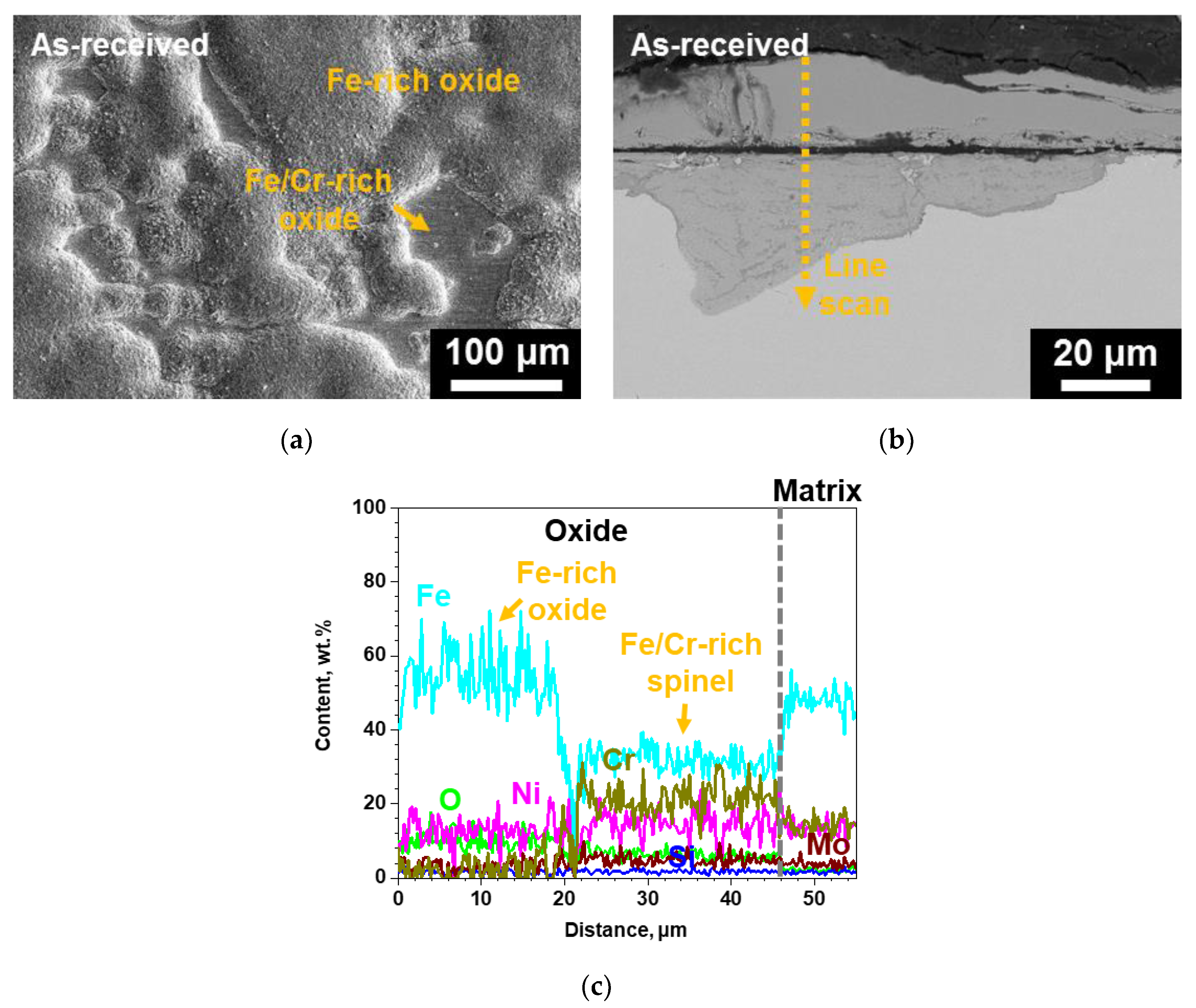
Figure 8 shows the surface SEM micrograph of the as-received SS 316LN corroded in steam. The surface is mostly covered in large Fe-rich oxides, while some thin continuous Cr-rich oxide regions can also be found. This is quite similar to that observed for the as-received SS 316LN after S-CO
2 exposure, only the extent of oxidation is greater in steam. Indeed, cross-sectional BSE micrograph shows that the Fe-rich oxides have thicknesses of greater than 40 μm (
Figure 8b). In addition, similar to that found in S-CO
2-exposed as-received specimen, the oxides are composed of outer Fe-rich oxide and inner Fe- and Cr-rich spinel (
Figure 8c).
The results of SEM analysis on the surface-modified SS 316LN after steam exposure are shown in
Figure 9. A continuous oxide layer without any signs of spallation can be seen on the surface (
Figure 9a). In case of its cross-section, the oxide is about 15 μm in thickness (
Figure 9b), which is significantly smaller than that formed on steam-exposed as-received specimen (
Figure 8b). Meanwhile, as shown in EDS line scan result in
Figure 10b, the oxide layer has a complex structure composed of various oxides. Still, from TEM analyses result on the oxide shown in
Figure 10, existence of Si-rich oxide can be seen below the outermost Fe-rich oxide. These observations are similar to those made in a previous work by Bolivar et al. in which 9Cr ferritic-martensitic steel (FMS) coated by Si using chemical vapor deposition (CVD) was subjected to steam oxidation at 650
oC for up to 3000 h [
16]. Si coating significantly reduced mass gains compared to those of the as-received alloy, which was ascribed to the formation of Si-rich oxide layer between the outer Fe-rich oxide and inner Fe- and Cr-rich spinel. Furthermore, Ishitsuka et al. reported similar corrosion behaviors and oxide structures for Si-containing FMS after high temperature steam exposure, and found the Si-rich oxides to be amorphous [
17]. TEM analyses performed on the Si-rich oxide formed on the surface-modified alloys after steam corrosion in this study also revealed it to be amorphous (not shown).
Furthermore, results of XRD analysis conducted on the as-received and surface-modified SS 316LN after steam corrosion test at 650 °C (0.1 MPa) for 500 h are shown in
Figure 11. For the as-received specimen, peaks of Fe
2O
3 and Fe
3O
4 oxides were detected, while only Fe
2O
3 was detected for the surface-modified SS 316LN. Matrix peaks were not detected for both specimens, because of the thickness of the oxides as seen in the cross-sectional BSE images. In previous works in which duplex oxide were formed on FMS after high temperature exposure, it was reported that the outer Fe-rich oxide was composed of outermost Fe
2O
3 layer under which Fe
3O
4 was formed [
18,
19]. It was proposed that Fe
3O
4 initially forms, when the supply of Fe to the oxidation front is sufficiently high. With continued growth and increase in thickness of Fe
3O
4 layer on FMS, outward diffusion of Fe cations from the matrix to the oxidation front decreases. Consequently, at some point during oxidation, Fe
2O
3 forms at the outermost region above Fe
3O
4, as Fe
2O
3 is stable at higher oxygen activities compared to Fe
3O
4 [
20]. This mechanism could be applied to the as-received SS 316LN oxidized in steam in this study, in view of its oxide products (Fe
2O
3 and Fe
3O
4) and structure (duplex oxide). On the other hand, the absence of Fe
3O
4 for the surface-modified specimen would be due to the formation of Si-rich oxides, which hampered outward diffusion of Fe ions. Therefore, it is quite apparent that Si-rich oxides formed on the surface-modified alloys contributed to slower corrosion kinetics in high temperature steam environment.
Meanwhile, it should be noted that thickness of the oxide layer formed on the surface-modified alloy in steam environment is about 15 μm (
Figure 9), which is greater than the thickness of the Si-enriched region of 9 μm (
Figure 2). This implies that the oxide growth in steam extended to below the entire surface-modified region. Voids found in the Si-enriched region for surface-modified alloy (
Figure 2) could not be observed along the entire sample. In addition, the Si content below the oxide layer of the surface-modified alloy in steam is about 1 wt.%, which is similar content as that detected in the matrix of the as-received SS 316LN. Despite the Si depletion after steam oxidation, surface Si-enrichment was effective in enhancement of oxidation resistance. However, sub-oxide depletion of an element participating in oxidation is a concern in oxide stability and there is a need for longer exposure tests in order to further validate the effectiveness of the surface-modification.


