Article

Chromium Diffusion Coating on an ODS Ferritic-Martensitic Steel and Its Oxidation Behavior in Air and Steam Environments

1
Department of Nuclear and Quantum Engineering, Korea Advanced Institute of Science and Technology, Daejeon 34141, Korea
2
Safety Materials Technology Development Division, Korea Atomic Energy Research Institute, Daejeon 34057, Korea
*
Author to whom correspondence should be addressed.
Coatings 2020, 10(5), 492; https://doi.org/10.3390/coatings10050492
Submission received: 23 April 2020 / Revised: 15 May 2020 / Accepted: 19 May 2020 / Published: 20 May 2020
(This article belongs to the Special Issue Advanced Coating for High Temperature Applications)

Abstract

:
A chromium diffusion coating was applied on an oxide dispersion strengthened ferritic-martensitic (ODS-FM) steel to improve oxidation resistance at high temperature. By carrying out physical vapor deposition followed by inter-diffusion heat treatment, a thin Cr-rich carbide layer was produced on the ODS-FM steel. Both the as-received and surface-modified specimens were oxidation-tested at 650 °C in air and steam environments for 500 h. The surface-modified specimens showed improved oxidation resistance in both environments. In an air environment, both conditions exhibited a thin and continuous chromia layer, but the formation of Cr2O3 and (Mn, Cr)3O4 nodules resulted in greater weight gain for the as-received specimen. In a steam environment, weight gain increased for both the as-received and surface-modified specimen. Especially, the as-received specimen showed much greater weight gain with the formation of a thick oxide layer consisted of outer Fe-rich oxide and inner (Fe, Cr, Mn) oxide layers. On the other hand, a thin and continuous chromia layer was formed for the surface-modified specimen, which resulted in much less weight gain in a steam environment.

1. Introduction

The operating temperature of power generation plants have been increasing to achieve better efficiency and meet the high demands of electricity [1,2]. For such high temperature applications, many heat-resistant alloys have been developed including ferritic-martensitic (FM) steels [3,4,5]. The FM steels show high strength, high creep resistance, and reasonable oxidation resistance to be used as structural materials in power plants. However, there is a concern that the high strength and creep resistance would be lost above 600 °C. To overcome the limitation, many researchers have studied oxide dispersion strengthened FM (ODS-FM) steels. In ODS-FM steels, numerous nano-oxide particles are uniformly dispersed, which hinder the dislocation movement and maintain the high strength and creep resistance at higher temperature up to 700 °C [6,7,8]. Nonetheless, the poor oxidation resistance of FM and ODS-FM steels has to be addressed for high temperature applications. Although some studies reported the nano-oxide particles made the oxidation rate slower, the oxidation rate was still too fast due to inherently low Cr contents [9,10]. In addition, when water vapor is present in the environment, the breakaway oxidation was reported for FM steels [11].
One of the ways to improve the oxidation resistance of FM and ODS-FM steels would be surface modification with oxidation resistant materials like Cr. Schmidt et al., applied chromium diffusion coatings on a FM steel, then conducted an oxidation test at 650 °C for 3000 h in Ar–50% H2O [12]. The surface modification by pack cementation produced Cr carbide layer on the FM steel and showed extremely lower weight gain as compared with the un-coated steel. Wu et al., have studied the oxidation behavior of a Cr-coated carbon steel in wet and dry air at 750 °C for up to 10 h [13]. A Cr carbide layer produced on the steel also resulted in lower weight gain after the oxidation test. Nonetheless, the evaluation of Cr diffusion coating on ODS-FM steels in steam environments was rarely reported.
Previously, a Cr diffusion coating method was developed by authors to improve oxidation resistance in supercritical carbon dioxide environment [14]. The Cr diffusion coating consisted of two steps: physical vapor deposition of a thin layer of Cr followed by inter-diffusion heat treatment. By separating Cr deposition and diffusion processes, elemental inter-diffusion and phase transformation were well controlled compared to the conventional diffusion coating where deposition and diffusion occur simultaneously. In this study, the developed Cr diffusion coating method was applied to an ODS-FM steel to modify the surface, and specimens were exposed to air and steam environments at 650 °C for 500 h. Then, weight changes were measured to evaluate the effect of surface modification on the oxidation resistance of ODS-FM steel. In addition, the characteristics of oxides and coating layer were discussed in view of the oxidation resistance and the stability of the coating layer.

2. Materials and Methods

2.1. Material and Surface Modification Procedure

A plate of recently developed ODS-FM steel, advanced radiation resistant ODS steel (ARROS) [8], was provided by Korea Atomic Energy Research Institute (KAERI). The nominal composition of ARROS alloy is listed in Table 1. To achieve proper mechanical property of FM steels, normalizing (1050 °C for 1 h) followed by tempering heat treatment (780 °C for 1 h) were carried out in air. The details of the thermo-mechanical process of the plate can be found in the previous publication [8]. For oxidation test, the ARROS plate was machined by electrical discharged machining (EDM) into coupon type specimens with 12 mm in diameter and 1 mm in thickness with a hanging hole of 1.5 mm in diameter. Prior to surface modification or oxidation test, the specimens were mechanically ground with 1200 grit SiC paper and ultrasonically cleaned in ethanol.
For surface modification with Cr diffusion coating, the coupon specimens were placed in a magnetron sputtering physical vapor deposition (PVD, magnetron sputtering system, ITS Co., Daejeon, Korea) equipment. The detailed deposition conditions are summarized in Table 2. Then, the PVD chamber was evacuated less than 3.0 × 10⁻⁶ torr, and DC power was applied to two guns of Cr target (99.95% pure Cr) for 1 h to produce 4 μm of Cr deposition layer. The Cr deposition process was repeated for the other side of the specimens. Then, inter-diffusional heat treatment (IDHT) was carried out to allow Cr diffusion into substrate, thereby to enhance the adherence of coating layer to substrate. The IDHT was performed at 1050 °C for 1 h in vacuum. The surface modified specimens were further heat treated at 780 °C for 1 h. The IDHT and subsequent heat treatment conditions are chosen to simulate the normalizing and tempering heat treatment conditions of ARROS alloy, therefore the specimens can maintain the same microstructure and mechanical properties. The detailed conditions for the surface modification can be found in authors’ previous study [14]. The ARROS specimen prepared by Cr diffusion coating was denoted as Cr-IDHTed ARROS.

2.2. High Temperature Oxidation Test in Air and Steam Environments

At least three coupon specimens of each condition (the surface-modified and the as-received) were exposed to 650 °C in air and pure steam environments for 500 h. A box furnace was used for the air oxidation test. For the steam oxidation test, a steam oxidation test equipment consisted of a quartz tube placed in the furnace was used. Coupon specimens were hung in the test zone of the quartz tube using a Pt wire with alumina spacers. During the test, the inside of the quartz tube was maintained at the target temperature while distilled water was supplied at a flow rate of 20 cc/min. The detailed design of the steam oxidation test equipment was well described elsewhere [15].
Before and after oxidation test, the specimens were weighed using a microbalance (XP6, Mettler Toledo, Columbus, OH, USA) with a resolution of 0.001 mg and maximum capacity of 6.1 g. For characterization of the microstructural feature after surface-modification and high temperature oxidation, analytical methods such as X-ray diffraction (XRD, D/MAX-2500, Rigaku, Tokyo, Japan) with a step size of 0.01°, field emission scanning electron microscope (FE-SEM, SU8230, Hitachi, Tokyo, Japan) equipped with energy dispersive X-ray spectroscope (EDS) and transmission electron microscope (TEM, Talos F200X, FEI Co, Hillsboro, OR, USA) were used. A resolution of FE-SEM and scanning TEM are 0.8 nm in 15 kV and 0.6 nm in 200 kV, respectively. Also, EDS can distinguish energy with a resolution of 125 and 136 eV in SEM and TEM, respectively. Focused ion beam (FIB, Helios Nanolab 450 F1, FEI Co., Hillsboro, OR, USA) was utilized to prepare TEM specimens with an ion beam resolution of 4 nm and 2.5 nm in a preferred statistical method and a selective edge method, respectively.

3. Results and Discussion

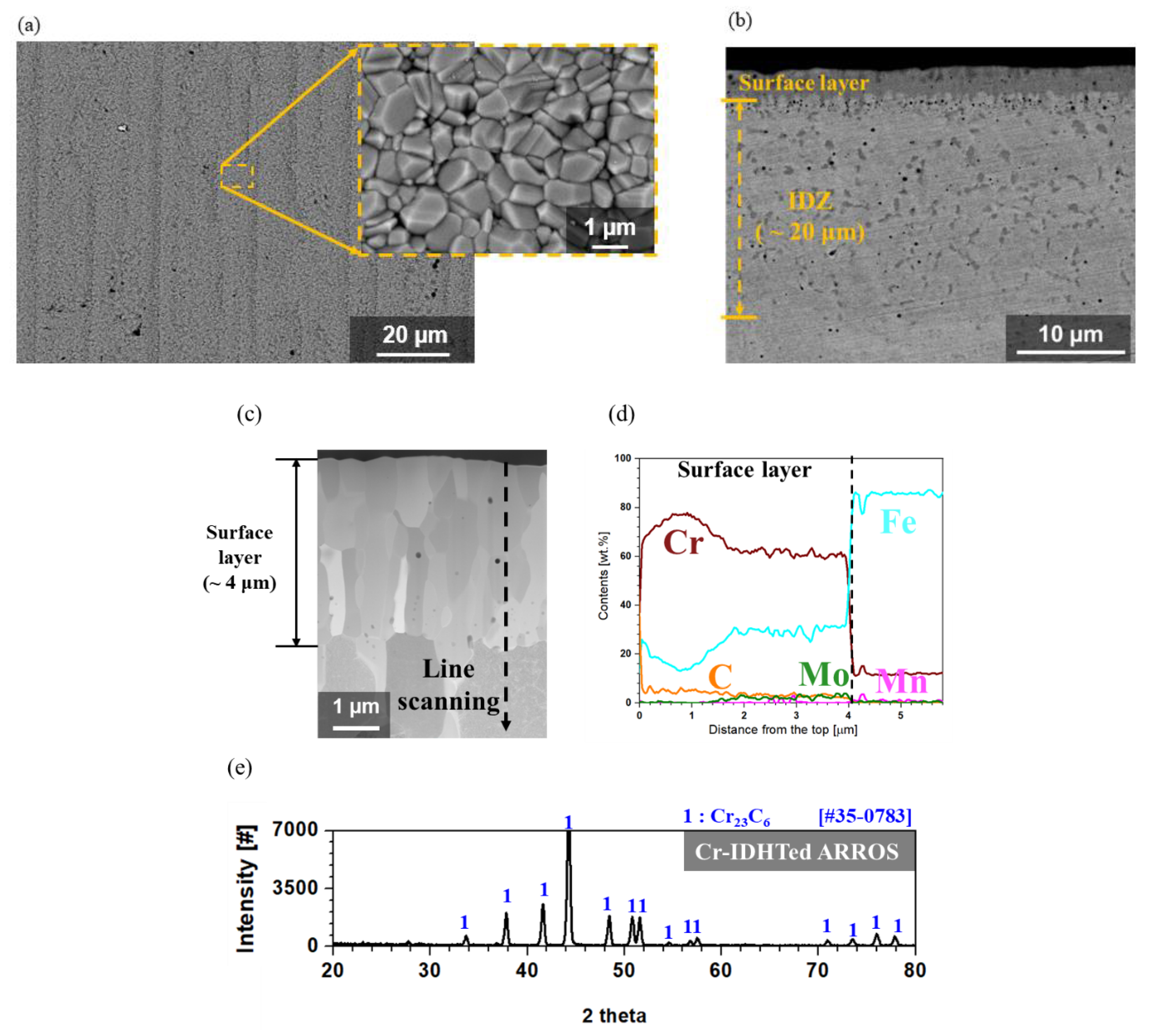
3.1. Characterization of the Surface-Modified Layer

Figure 1 shows the cross-sectional back-scattered SEM (BS-SEM) image, scanning TEM (STEM) image, EDS line scanning result and XRD result of the Cr-IDHTed ARROS. Figure 1 shows the surface oxide morphology, the cross-sectional back-scattered SEM (BS-SEM) image, scanning TEM (STEM) image, EDS line scanning result and XRD result of the Cr-IDHTed ARROS. As shown in Figure 1a, the surface of Cr-IDHTed ARROS was covered with densely packed particles. Also, the inter-diffusion zone (IDZ) was formed with a depth of around 20 μm (Figure 1b), which showed slightly higher Cr content and more carbides than the ARROS substrate in previous study [14]. Nonetheless, since this study focused only on the role of surface layer on high temperature oxidation, details on IDZ were not dealt in this paper. As shown in Figure 1c,d, a 4 μm-thick surface layer was produced on the Cr-IDHTed ARROS. The surface layer was rich in Cr (approximately 60 wt.%) and Fe (approximately 30 wt.%), which can act as a Cr reservoir during high temperature exposure. As shown in EDS line scanning result (Figure 1d), Cr content was higher in outer part of the layer than the inner part of the layer. On the other hand, Fe and Mo content were lower in the outer part of the layer. Carbon content was slightly higher in the outer part of the layer where Cr content was also higher, as gradually decreasing toward the surface layer/substrate interface. Based on the EDS line scanning results (Figure 1d) and XRD result (Figure 1e), it could be said that the surface layer is Cr-rich M23C6. Similar Cr-rich carbide layer was reported after diffusion coating on FM steel to improve oxidation resistance [12].
Considering the report on the spontaneous formation of Cr-rich carbide at 1050 °C [16] and the diffusivities of elements in body centered cubic (BCC) matrix [17], it could be stated that the surface layer on the Cr-IDHTed ARROS was formed as follows. The pure Cr deposition layer and the ARROS substrate inter-diffused slowly during the IDHT at 1050 °C. At the same time, C rapidly diffused into the surface layer and reacted with Cr to form Cr-rich carbide layer. When Cr-rich carbide layer was formed, the inter-diffusion between the surface layer and substrate slowed down rapidly. Therefore, the most of deposited Cr would remain in the surface layer as Cr-rich carbides.

3.2. Weight Changes after Air and Steam Oxidation Test

Weight changes of the as-received and Cr-IDHTed ARROS after oxidation test in air and steam at 650 °C for 500 h are shown in Figure 2. Compared to the as-received ARROS, the Cr-IDHTed ARROS showed much lower weight changes in both air and steam environments. Meanwhile, the as-received ARROS showed lower weight gain in both environment than commercial 9 Cr FM steel (approximately 1.5 mg/cm2 in air and 9 mg/cm2 in steam [18]).

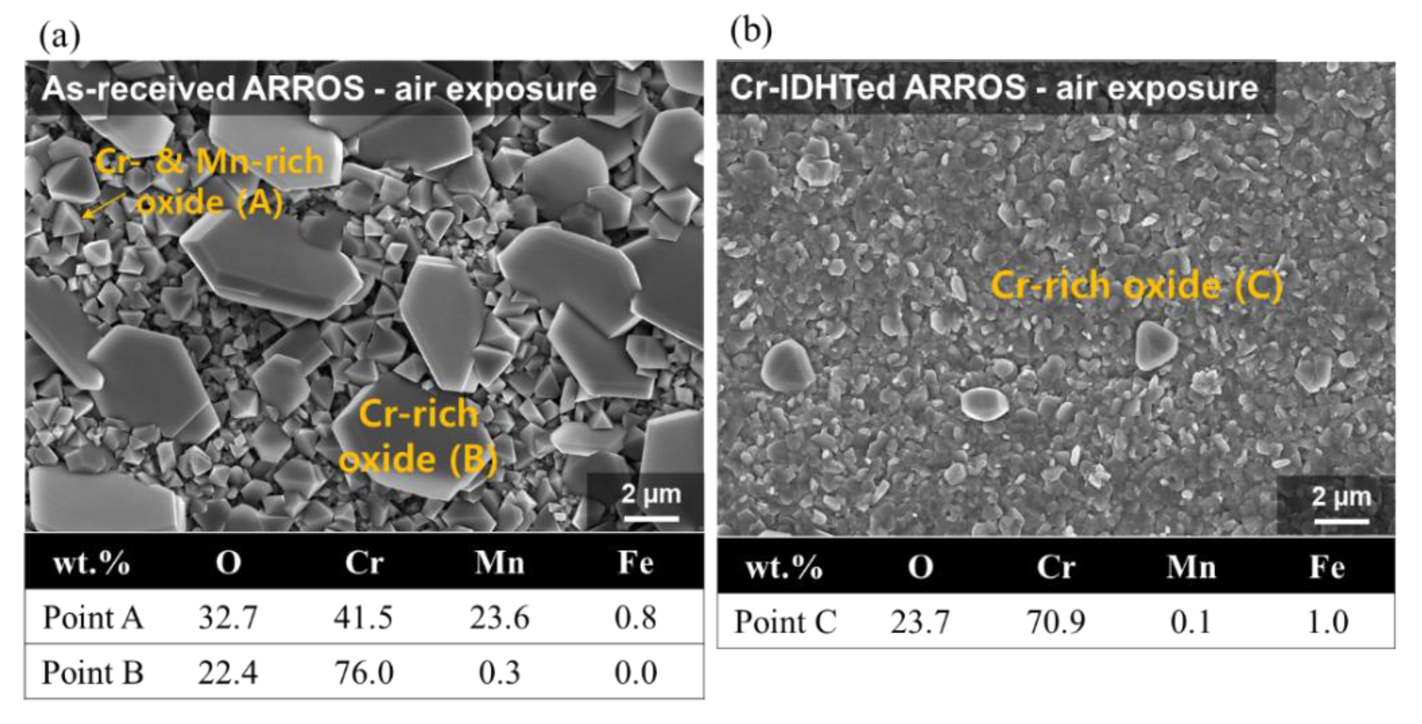
3.3. Oxidation Behavior in Air Environment

The SEM images of the surface oxides formed on the as-received and Cr-IDHTed specimens tested in air are shown in Figure 3. For both the as-received and Cr-IDHTed specimens, Cr-rich oxides were formed, but the compositions of the Cr-rich oxides were slightly different, which were analyzed by a point EDS method. In the as-received specimen (Figure 3a), two distinctively different oxides were found on the surface: the big Cr-rich nodules and smaller Cr- and Mn-rich particles, which was later confirmed by the XRD analysis (Figure 4) and TEM/EDS analysis (Figure 5) results. For the as-received specimen tested in air, the XRD peaks of Cr2O3, (Mn, Cr)3O4, and the substrate (BCC) were observed. The detection of substrate by XRD suggested that a thin oxide layer was formed. Figure 5 shows the cross-sectional oxide morphology of the as-received specimen tested in air. In the STEM/EDS mapping results, it was found that the nodules and particles shown in Figure 3a were consisted of Cr-rich oxides and Mn- and Cr-rich oxides, while the thin and continuous chromia layer with thickness of 200 nm was formed below those particles. Also, it was found that Cr content was reduced from 9 wt.% to 4 wt.% below the continuous chromia layer (Figure 5b), which suggest that there may be not enough Cr supply to support continuous chromia layer during the long-term high temperature exposure.
For the Cr-IDHTed specimen tested in air, only fine Cr-rich oxides were found on the surface (Figure 3b). These small oxide particles were confirmed as Cr2O3 by XRD analysis (Figure 4). The presence of XRD peaks of the surface layer (Cr23C6) indicated that the chromia layer would be thin, which was confirmed in Figure 6. Also, Figure 6 shows the cross-sectional STEM/EDS mapping and EDS line scanning results of the Cr-IDHTed specimen after the air oxidation test. As shown in the figure, a continuous chromia layer with a thickness of 200 nm and nodular chromia were formed. EDS mapping and line scanning results confirmed that there was little partitioning of other element in both type of chromia. Underneath the continuous chromia layer, some Cr depletion was found at grain boundaries below the oxide/surface layer interface. Nevertheless, Cr content in the surface layer was maintained at approximately 60 wt.% and the carbide phase of the surface layer was not changed after the oxidation test in air as shown in XRD result (Figure 4)
Through the oxide analyses, it can be said that the difference in the weight changes of the as-received and Cr-IDHTed specimens came from the formation of the big Cr-rich (with some Fe) oxides and (Mn, Cr)3O4 nodules. Although both conditions of ARROS had same thickness of the continuous chromia layer (~200 nm), the big Cr-rich oxides and (Mn, Cr)3O4 nodules were formed on only the as-received specimen. Such duplex oxide layer of M3O4 and M2O3-type oxides (M: Fe, Cr, or Mn) on the alloys with Mn content below 1 wt.% have been reported in air environment [19]. When the duplex oxide layer was formed, it was observed that the initial slow oxidation rate changed to the faster rate. The initial slow oxidation was associated with the formation of Cr2O3. When the chromia become dense and continuous, it is hard for Cr cations to diffuse through the dense Cr2O3 layer and the oxidation kinetics would be slow. However, the diffusivity of Mn cations through Cr2O3 was known to be orders of magnitude greater than Cr cations [20], resulting in the formation of (Mn, Cr)3O4 (Figure 5). Meanwhile, since Mn would diffuse much slower in the carbide layer than in BCC matrix, it is hard to observe Mn in the M23C6 surface layer or surface chromia layer for the Cr-IDHTed ARROS as shown in Figure 6. Thus, the Cr-IDHTed specimen showed much lower weight gain than the as-received one because the surface-modified layer suppressed the diffusion of Mn cation and prevented the formation of (Mn, Cr)3O4 nodules on the surface.

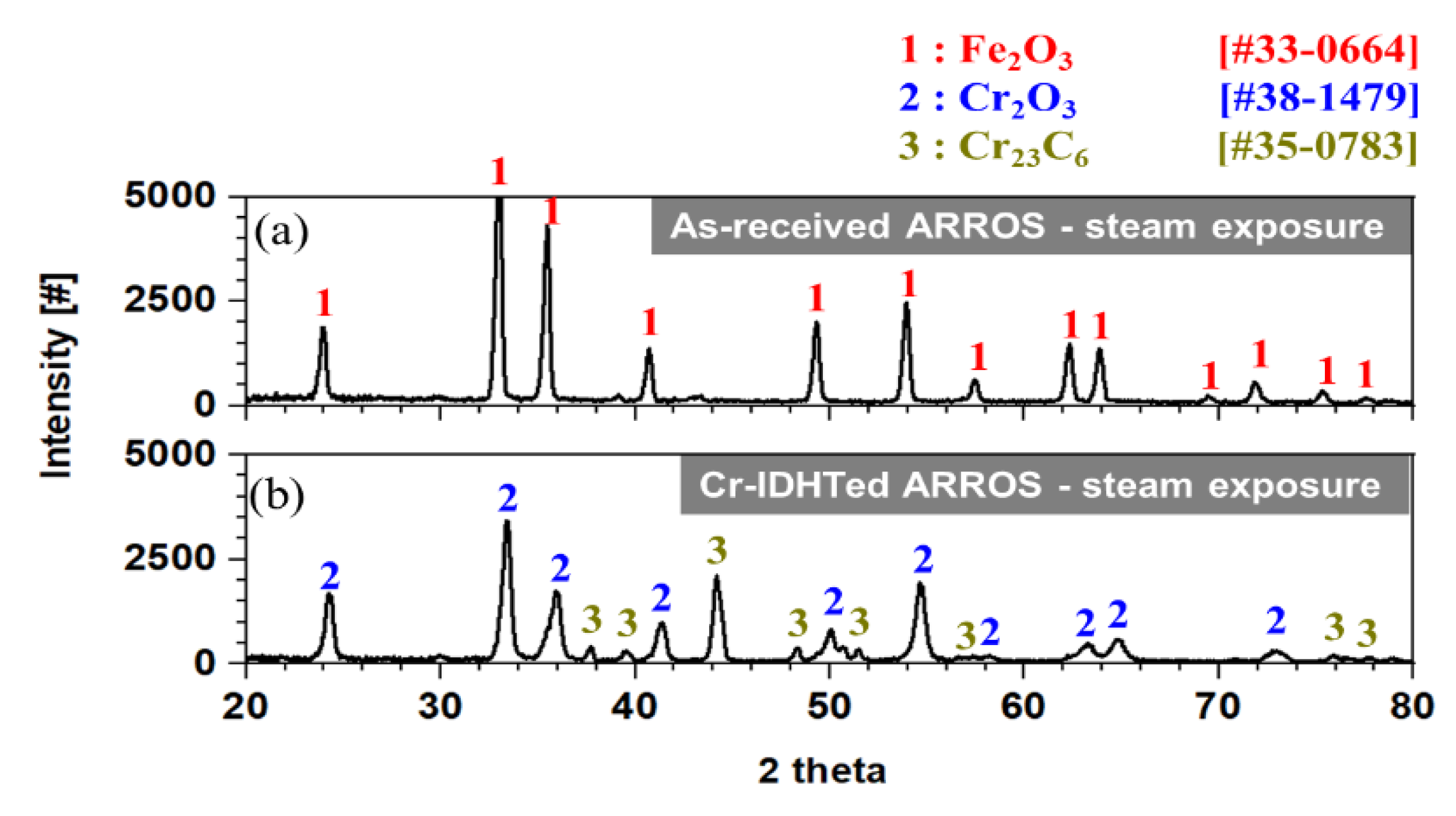
3.4. Oxidation Behavior in Steam Environment

After the steam oxidation test, the surface oxides were observed under SEM and the results are shown in Figure 7. Compared to the specimens tested in air, the as-received and Cr-IDHTed specimens showed somewhat different surface oxide morphology in steam environment. For the as-received specimen, some of surface oxide layer was spalled off and Fe-rich oxides were detected by point EDS analysis. On the other hand, only fine chromia were formed on the Cr-IDHTed specimen. Figure 8 shows the XRD results of the specimens after steam oxidation test at 650 °C for 500 h. While all peaks of the as-received specimen matched to those of hematite (Fe2O3), XRD peaks of the Cr-IDHTed specimen matched to those of the Cr2O3 and the surface layer (Cr23C6). The absence of the peaks of substrate for the as-received specimen indicates the hematite layer would be thick, which was confirmed in a cross-sectional SEM image in Figure 9. Meanwhile, the XRD peaks of the Cr23C6 surface layer were observed for the Cr-IDHTed specimen, which suggest that the oxide layer would be thin (Figure 10) even in steam environment.
The cross-section of the specimens tested in steam was analyzed using SEM and the results are shown in Figure 9. Thick oxide layers were formed on the as-received specimen, which was consisted of three zones such as a thick (~15 μm) outer Fe oxide layer, (Fe, Cr, Mn) oxide layer and the isolated Fe-rich or Cr-rich oxides (Figure 9b). In the outer Fe oxide layer, voids and cracks were found. Meanwhile, cross-sectional STEM analyses were conducted on the oxide layer of the Cr-IDHTed specimens because the oxide layer was too thin to be observed by SEM. Figure 10 shows cross-sectional STEM/EDS mapping and EDS line scanning results for Cr-IDHTed specimens oxidized in steam. A thin and continuous chromia layer (about 400 nm thick) was formed. Some voids and Cr depletion below them were observed under the chromia layer. The formation of the void and Cr depletion will be discussed in the following section.
Based on the oxide analysis results, it could be said that thick Fe-rich oxides (~25 μm) on the as-received specimen and the thin chromia layer on the Cr-IDHTed specimen resulted in huge difference in the weight change shown in Figure 2 (4.7 mg/cm2 for the as-received specimen, 0.38 mg/cm2 for the Cr-IDHTed specimen). The rapid oxidation behavior and formation of thick Fe-rich oxides on 9Cr FM steels in steam environment was reported previously [21], suggesting the presence of water vapor changed the oxidation behavior of 9Cr steels. For the as-received ARROS, the failure of forming the protective chromia in steam environment could be explained considering two mechanisms. One is the chromia volatilization and the other is accelerated oxygen diffusion by water vapor. Because chromia volatilization can be negligible at temperature below 800 °C in pure steam [22], the accelerated oxygen diffusion in oxide layer in steam would be the main reason for the enhanced oxidation rate. At the early stage of oxidation, Cr-rich oxides were formed on the surface of the as-received specimen. However, Cr would be depleted rapidly due to rapid oxygen diffusion and relatively slow Cr diffusion. Therefore, Fe-rich oxides with fast kinetics were produced by breaking the Cr-rich oxide layer [11,21]. According to the literature, the outer Fe-oxide layer was hematite, which was consistent with the observation of this study. Underneath the hematite, (Fe, Cr, Mn) oxide layer was present, which would be (Fe, Cr, Mn)3O4 and large fluctuation of Cr and Fe contents was present near the oxide/metal interface as shown in EDS line scanning results (Figure 9b). The Fe-rich and Cr-rich particles could be FeO and Cr2O3, respectively, as reported previously [21]. Therefore, it could be said that although ODS-FM steel showed relatively lower oxidation rate than commercial FM steel, a thick Fe-rich oxide layer was found in steam environment due to low Cr content. On the contrary, the Cr-IDHTed specimen showed a thin and continuous chromia layer because of the presence of the surface layer highly enriched with Cr (~60 wt.%). Similar to the air oxidation test, the Cr and Fe contents in the surface layer were maintained after the steam oxidation test.

3.5. Effect of Environments on the Oxidation Behaivor of the Cr-IDHTed Layer

As shown in the weight change results (Figure 2), the as-received specimen exhibited the huge different oxidation behavior in air and steam. The effect of water vapor on the oxidation behavior of FM steels have been widely studied [11,18,21]. Although the presence of nano-oxide particles somewhat improved the oxidation behavior in FM-ODS, the phenomena were quite similar to that of FM steels. Therefore, the effect of steam environment on the oxidation behavior of the Cr-IDHTed ARROS was further discussed in this section. As shown in the weight change results (Figure 2) and cross-sectional STEM images of the Cr-IDHTed specimens tested in air and steam (Figure 6 and Figure 10, respectively), the thicker chromia layer was formed in steam environment. In addition, large voids and Cr-depleted region were observed at the oxide/surface layer interface. Almost pure Fe oxides were detected in the Cr-depleted region. Some researchers have studied on the water vapor effect on chromia-forming alloys and reported that chromia formed in steam had more adherent and finer grains than chromia formed in air [23,24,25]. By conducting two-stage oxidation test with isotopes, it is found that chromia is formed by outward diffusion in air but chromia is produced by inward diffusion in steam [23]. Owing to the difference in chromia formation, it is reported that the chromia formed in air had more voids at the oxide/metal interface from the condensation of vacancies. On the other hand, the chromia formed in steam had less voids and more adherent as the new chromia formed at the oxide/metal interface by inward diffusion. However, the chromia formed on the Cr-IDHTed layer in this study showed different behavior. At the oxide/surface layer (Cr23C6) interface, the oxidation of Cr-rich carbides would release carbon-containing gases or carbon-ions as by-products [13]. Then, the by-products would be removed rapidly through fine gains of chromia and/or grain boundaries of the Cr-IDHTed layer. As a result of the removal of by-products of the oxidation reaction at the oxide/surface layer interface, the large voids and Cr-depleted regions below them were formed as shown in Figure 10a. As mentioned above, chromia formed in steam showed somewhat finer grains than chromia formed in air, oxygen diffusion through grain boundary and oxidation would be enhanced. Therefore, it is summarized that the higher weight gain (Figure 2) and larger voids (Figure 10) of Cr-IDHTed specimen in steam environment were caused by enhanced inward diffusion of oxygen.

4. Conclusions

To improve high temperature oxidation resistance, an oxide dispersion strengthened ferritic-martensitic (ODS-FM) steel was surface-modified by Cr diffusion coating method. The surface modification was performed by magnetic sputtering PVD followed by inter-diffusion heat treatment, which produced Cr-rich M23C6 layer with a 4-μm thickness (Cr-IDHTed). Then, high temperature oxidation tests were performed in air and steam environments at 650 °C for 500 h. Based on the oxidation test results and subsequent analyses, the following conclusions were drawn:
  • The surface-modified specimens showed enhanced oxidation resistance in both air and steam environments showing much smaller weight gains compared to the as-received specimens;
  • In an air environment, while the as-received specimens formed Cr2O3 and (Mn, Cr)3O4 nodules and a thin chromia layer, the Cr-IDHTed specimen showed only thin chromia as the surface layer prevented outward diffusion of Mn from the matrix;
  • In a steam environment, while thick oxide layers consisted of outer Fe-rich oxide layer and inner (Fe, Cr, Mn) oxide layer was formed on the as-received specimen, a thin and continuous chromia layer was formed on the Cr-IDHTed one because of enough Cr reservoir in the surface layer;
  • In the surface layer of the Cr-IDHTed specimen, larger voids and finer grains were observed after oxidation test in steam. Rapid inward diffusion of oxygen to the oxide/surface layer interface in steam environment was responsible for higher weight gain and larger void formation.

Author Contributions

Conceptualization, C.J.; formal analysis, S.H.K.; investigation, C.K. and J.-H.C.; data curation, C.K.; writing—original draft preparation, C.K.; writing—review and editing, C.J.; supervision, C.J.; project administration, T.K.K. All authors have read and agreed to the published version of the manuscript.

Funding

This study was supported by the two Nuclear R&D programs (Nos. 2020M2A8A4025453 and 2020M2A8A4023937) of MSIT/NRF of Rep. of Korea. Financial support for three of the authors is provided by the BK-Plus Program of the MSIT/NRF of the Rep. of Korea.

Acknowledgments

The ARROS plate, which was used in this paper, was provided by Sanghoon Noh of KAERI.

Conflicts of Interest

The authors declare no conflict of interest.

References

  1. Gianfrancesco, A.D. The fossil fuel power plants technology. In Materials for Ultra-Supercritical and Advanced Ultra-Supercritical Power Plants, 1st ed.; Gianfrancesco, A.D., Ed.; Woodhead Publishing: Duxford, UK, 2017; pp. 1–49. [Google Scholar]
  2. Yoo, J.; Chang, J.; Lim, J.-Y.; Cheon, J.-S.; Lee, T.-H.; Kim, S.K.; Lee, K.L.; Joo, H.-K. Overall system description and safety characteristics of Prototype Gen IV Sodium Cooled Fast Reactor in Korea. Nucl. Eng. Technol. 2016, 48, 1059–1070. [Google Scholar] [CrossRef] [Green Version]
  3. Kern, T.-U.; Staubi, M.; Scarlin, B. The european efforts in material development for 650 °C USC power plants-COST522. ISIJ Int. 2002, 42, 1515–1519. [Google Scholar] [CrossRef]
  4. Masuyama, F. History of power plants and progress in heat resistant steels. ISIJ Int. 2001, 41, 612–625. [Google Scholar] [CrossRef]
  5. Zhou, X.; Liu, C.; Yu, L.; Liu, Y.; Li, H. Phase transformation behavior and microstructural control of high-Cr martensitic/ferritic heat-resistant steels for power and nuclear plants: A review. J. Mater. Sci. Technol. 2015, 31, 235–242. [Google Scholar] [CrossRef]
  6. Kleh, R.L.; Hashimoto, N.; Maziasz, P.J. Development of new nano-particle-strengthened martensitic steels. Scripta Mater. 2005, 53, 275–280. [Google Scholar] [CrossRef]
  7. Ukai, S.; Ohtsuka, S.; Kaito, T.; Carlan, Y.; Ribis, J.; Malaplate, J. Oxide dispersion-strengthen/ferrite-martensite steels as core materials for Generation IV nuclear reactors. In Structural Materials for Generation IV Nuclear Reactors, 1st ed.; Yvon, P., Ed.; Woodhead Publishing: Duxford, UK, 2017; pp. 357–414. [Google Scholar] [CrossRef]
  8. Kim, T.K.; Noh, S.; Kang, S.H.; Park, J.J.; Jin, H.J.; Lee, M.K.; Jang, J.; Rhee, C.K. Current status and future prospective of advanced radiation resistant oxide dispersion strengthened steel (ARROSS) development for nuclear reactor system applications. Nucl. Eng. Technol. 2016, 48, 572–594. [Google Scholar] [CrossRef] [Green Version]
  9. Quadakkers, W.J.; Holzbrecher, H.; Briefs, K.G.; Beske, H. Differences in growth mechanisms of oxide scales formed on ODS and conventional wrought alloys. Oxid. Met. 1989, 32, 67–88. [Google Scholar] [CrossRef]
  10. Chen, Y.; Srindharan, K.; Ukai, S.; Allen, T.R. Oxidation of 9Cr oxide dispersion strengthened steel exposed in supercritical water. J. Nucl. Mater. 2007, 371, 118–128. [Google Scholar] [CrossRef]
  11. Ehlers, J.; Young, D.J.; Smaardijk, E.J.; Tyagi, A.K.; Penkalla, H.J.; Singheiser, L.; Quadakkers, W.J. Enhanced oxidation of the 9%Cr steel P91 in water vapour containing environments. Corros. Sci. 2006, 48, 3428–3454. [Google Scholar] [CrossRef]
  12. Schmidt, D.; Galetz, M.C.; Schutze, M. Ferritic-martensitic steels: Improvement of the oxidation behavior in steam environments via diffusion coatings. Surf. Coat. Technol. 2013, 237, 23–29. [Google Scholar] [CrossRef]
  13. Wu, S.; Guo, B.; Li, T.; Gui, D. Oxidation of chromium carbide coated Q235 steel in wet and dry air at 750 °C. Constr. Build. Mater. 2015, 81, 11–14. [Google Scholar] [CrossRef]
  14. Kim, C.; Kim, S.H.; Cha, J.-H.; Jang, C.; Kim, T.K. Cr diffusion coating to improve the corrosion resistance of an ODS steel in super-critical carbon dioxide environment. Surf. Coat. Technol. 2019, 374, 666–673. [Google Scholar] [CrossRef]
  15. Kim, D.; Kim, D.; Lee, H.J.; Jang, C.; Yoon, D.J. Corrosion characteristics of Ni-base superalloys in high temperature steam with and without hydrogen. J. Nucl. Mater. 2013, 441, 612–622. [Google Scholar] [CrossRef]
  16. Ren, P.; Zhu, S.; Wang, F. Spontaneous reaction formation of Cr23C6 diffusion barrier layer between nanocrystalline MCrAlY coating and Ni-base superalloy at high temperature. Corros. Sci. 2015, 99, 219–226. [Google Scholar] [CrossRef]
  17. Kučera, J.; Stránský, K. Diffusion in iron, iron solid solutions and steels. Mater. Sci. Eng. 1982, 52, 1–38. [Google Scholar] [CrossRef]
  18. Sundararajan, T.; Kuroda, S.; Kawakita, J.; Seal, S. High temperature corrosion of nanoceria coated 9Cr-1Mo ferritic steel in air and steam. Surf. Coat. Technol. 2006, 201, 2124–2130. [Google Scholar] [CrossRef]
  19. Jian, L.; Jian, P.; Bing, H.; Xie, G. Oxidation kinetics of Haynes 230 alloy in air at temperature between 650 and 850 °C. J. Power Sources 2006, 159, 641–645. [Google Scholar] [CrossRef]
  20. Lobnig, R.E.; Schmidt, H.P.; Hennesen, K.; Grabke, H.J. Diffusion of cations in chromia layer grown on iron-base alloys. Oxid. Met. 1992, 37, 81–93. [Google Scholar] [CrossRef]
  21. Quadakkers, W.J.; Ennis, P.J.; Zurek, J.; Michalik, M. Steam oxidation of ferritic steels-laboratory test kinetic data. Mater. High. Temp. 2005, 22, 47–60. [Google Scholar] [CrossRef]
  22. Young, D.J. Effects of water vapour on the oxidation of chromia formers. Mater. Sci. Forum 2008, 595–598, 1189–1197. [Google Scholar] [CrossRef]
  23. Zurek, J.; Young, D.J.; Essuman, E.; Hänsel, M.; Penkalla, H.J.; Niewolak, L.; Quadakker, W.J. Growth and adherence of chromia based surface scales on Ni-base alloys in high- and low-pO2 gases. Mater. Sci. Eng. A 2008, 477, 259–270. [Google Scholar] [CrossRef]
  24. Othman, N.K.; Othman, N.; Zhang, J.; Young, D.J. Effects of water vapour on isothermal oxidation of chromia-forming alloys in Ar/O2 and Ar/H2 atmospheres. Corros. Sci. 2009, 51, 3039–3049. [Google Scholar] [CrossRef]
  25. Nguyen, T.D.; Zhang, J.; Young, D.J. Effect of silicon and water vapour on corrosion of Fe-20Cr and Fe-20Cr-20Ni alloys in CO2 at 650 °C. Oxid. Met. 2017, 87, 541–573. [Google Scholar] [CrossRef]
Figure 1. Analyses of the surface layer of the Cr-inter-diffusional heat treatment (Cr-IDHTed) ARROS: (a) surface morphology, (b) cross-sectional back-scattered scanning electron microscope (BS-SEM) image, (c) scanning transmission electron microscope (STEM) image, (d) energy dispersive X-ray spectroscope (EDS) line scanning results along the line in (c), and (e) X-ray diffraction (XRD) result of the surface layer.
Coatings 10 00492 g001
Figure 2. Weight changes of the as-received and Cr-IDHTed ARROS after air and steam oxidation test at 650 °C for 500 h.
Coatings 10 00492 g002
Figure 3. Surface oxide morphologies and EDS point analysis of (a) the as-received and (b) Cr-IDHTed ARROSs after air oxidation test at 650 °C for 500 h.
Coatings 10 00492 g003
Figure 4. XRD results of: (a) the as-received and (b) Cr-IDHTed ARROSs after air oxidation test using a 2-theta scan mode.
Coatings 10 00492 g004
Figure 5. Cross-sectional TEM analyses of the as-received ARROS after air oxidation test at 650 °C for 500 h: (a) STEM/EDS mapping results and (b) EDS line scanning result along the line in (a).
Coatings 10 00492 g005
Figure 6. Cross-sectional TEM analyses of the Cr-IDHTed ARROS after air oxidation test at 650 °C for 500 h: (a) STEM/EDS mapping results and (b) EDS line scanning result along the line in (a).
Coatings 10 00492 g006
Figure 7. Surface oxide morphologies on: (a) the as-received and (b) Cr-IDHTed ARROSSs after steam oxidation test at 650 °C for 500 h.
Coatings 10 00492 g007
Figure 8. XRD results of: (a) the as-received and (b) Cr-IDHTed ARROSs after steam oxidation test at 650 °C for 500 h.
Coatings 10 00492 g008
Figure 9. (a) Cross-sectional SEM image and (b) EDS line scanning result of the as-received ARROS after steam oxidation test at 650 °C for 500 h.
Coatings 10 00492 g009
Figure 10. (a) Cross-sectional STEM image and EDS mapping results and (b) EDS line scanning result along the line in (a) of the Cr-IDHTed ARROS after steam oxidation test at 650 °C for 500 h.
Coatings 10 00492 g010
Table 1. The nominal chemical composition of advanced radiation resistant oxide dispersion strengthened (ODS) steel (ARROS) alloy used in this study.
FeCrMoMnVTiCY2O3
Bal.910.50.10.20.150.25
Table 2. Magnetron sputtering physical vapor deposition (PVD) parameters used in this study.
TargetNumber of GunsMode (Power)TimeWorking Pressure (Ar)Base PressureCoating Thickness
Cr (99.95%)2 gunsDC (250 W)1 h0.003 torr≤3.0 × 10⁻⁶ torr~4 μm

