1. Introduction
With the prosperity of international trade, port and shipping companies have developed rapidly [
1,
2]. Shipping safety has become increasingly prominent. Especially in emergency situations, fast, accurate and reliable information is needed to safely maneuver the ship [
3]. In this context, it is necessary to improve existing shipping models to provide theoretical support for the optimization and development of the shipping industry [
4,
5]. This will be of great significance to the development of the shipping industry. In the development of shipping and ocean engineering, towing operations have become increasingly important. With the development of the towing industry, there have been many new problems that need to be studied and resolved. The more prominent one is the coordinated maneuvering of large ships assisted by multiple tugs. Tugboat operation is mainly to assist ships in and out of port. A reasonable tugboat configuration will save port production costs, improve port operation efficiency, and provide the most favorable guarantee for the development of a port logistics system [
6].
At present, many ports attach great importance to the intelligent work quality of tugboat teams of tugboat enterprises—for example, Shanghai port, Shenzhen port, and other ports with large and frequent business volume. The fourth phase project of Yangshan Port, which is under construction, will be the first show of an unmanned intelligent port. The efficiency of tug-assisted ship handling has a great impact on the efficiency of port operation. Whether the ship can be loaded and unloaded as soon as possible depends on whether the tugboat can use the optimal scheduling strategy to drag the waiting ship into the appropriate berth. A scan be seen from the above analysis, it is necessary to create a reasonably structured and well-trained tugboat fleet. Under this premise, the auxiliary rationalization of tugs and the coordination of berths can ensure the safety of ships and accurate access to fairways and berths. The port’s production efficiency will be improved, the use cost of tugboat will also be reduced, and the competitiveness of tugboat enterprises in the market will be improved [
7].
In port engineering, the manipulation of ships and the rational allocation of tugs have always been a research focus of scholars. They have done a lot of corresponding research on ship maneuvering with the cooperation of multiple tugs.
In the research of ship maneuvering, with the development of ships, the working area of the harbor is limited, and the increase of navigation density also increases requirements. At present, the main method of ship maneuvering research is to establish a corresponding mathematical model and to carry out experimental research according to the actual process of ship maneuvering. The main research was as follows: in the 1980s, Bangzhi and others took the omni-directional tugboat model as an example, conducted in-depth research on the propeller force and hydrodynamic force of the tugboat, analyzed the interference effect between the tugboat and the tugboat, and carefully studied and evaluated the operation capability of the tugboat. A mathematical model was established between the ship and the tug, which set a precedent for future research [
8]. In the 1990s, Kobayashi and Osaka [
9] fully considered the interference effect of the ship itself on the propeller and steering gear under low-speed navigation conditions, and conducted digital simulation experiments on them. The experimental results basically coincided with the model tests. Fang et al. used linear system theory for analysis and modeling, combined with the characteristics of the towing movement, and used time domain research methods to draw the following conclusions: by changing the length of the towline and changing the position of the towing point of the tug, the ship and the tug can be combined and this towing system reduces volatility and maintains stability [
10,
11]. Inoue also used the linear system theory to study the course stability of the towing system, and studied the characteristics of the towing system under different conditions [
12]. One of the breakthrough points of Inoue’s research was to model the suspension chain model of the tugboat’s cable. It is assumed that the towing line is symmetrical in front and back in the equilibrium state of the towing. The disturbance mathematical model of the towing system is obtained by using the disturbance of the towline in the towing process. The relationship and influence between the quality of the streamer, the elasticity of the streamer, and the stability of the towing motion can be obtained [
13]. Based on the classical linear time invariant towing system theory, Charters et al. analyzed the effect of shallow water factors on the course stability of four typical towed ships, and obtained the parameter values of the course stability of the towing system [
14]. Tao Jiang applied the nonlinear system theory to study the directional stability of the Proportion-Integral-Derivative (PID) rudder traction system, and compared this with the previous linear system method, indicating the superiority of the nonlinear system theory in the corresponding towing research [
15]. In 2014, Ivan Catipovie et al. used a time-domain numerical model [
16] to systematically analyze the towline tension of a tug under the action of waves. In 2015, S. Hara et al. studied the tension exerted by the streamer on the patrol boat [
17].
Yang et al. carefully calculated the practical estimation method of the tugboat hydrodynamic force and the tugboat Z-tube four-quadrant thrust coefficient, established a more accurate tugboat auxiliary ship simulation model, and carried out digital simulation on it. In the end, they got more accurate simulation results [
18].Wang established a certain reference value in the study of the maximum speed of ship tugs [
19]. Zhang ignored the reaction force of the towed ship on the tugboat in the experimental research, simulated the movement of the tugboat towing the large ship through the elastic cable towing, and made a preliminary judgment on the course stability of the towing system [
20]. When studying the influence of towing on the reaction force of tug boat, Zhu established the nonlinear integral dynamic model of towing cable and towing ship, and simulated the stability of the towed ship in still water and a wave environment under ship-heading control, and creatively summarized the reasonable matching resistance point positioning method from the experiment [
21]. Yan and Huang have done a lot of research on the maneuvering motion of towing systems and published many papers. In this paper [
22], the gradual slow motion process is used in the maneuvering process of the towing system, and the nonlinear part of the hydrodynamic force is ignored. A complete mathematical model of the towing system is established in wind and waves. The stability of the control motion process of the towing system in the still water environment is discussed, the influence of the towing speed, the length of the towline, the trim and the wind current conditions on the towing maneuverability of the tug, and the influence of the change of streamer tension are analyzed. At the same time, Qi and Zhu [
23] conducted an experimental study on the motion of the towing system in an irregular wave environment, and analyzed the influence of the length of the towing cable, the towing speed on the towing motion, and the influence of the wave direction on the towing motion. Lovska and Píštěk studied the dynamic loading and strength of wagons using mathematical and computer modelling [
24]. Esposito [
25,
26] adapted the quality function in several important ways to accommodate the distributed nature of a large swarm of autonomous tugboats towing a ship. Thrust grouping and sequential quadratic programming method was first used to achieve the thrust allocation and control of four tugs [
27]. Bui [
28] used the redistributed pseudo-inverse algorithm to determine the thrust and direction of four tugboats to berth a ship. A control method was proposed for the large ship berthing by using tugboat formation [
29].
In summary, the technical difficulties of multi-tugs assisting ship maneuvering mainly include the following two points: (a) coordination and cooperation between tugs and (b) analysis of forces acting on tugs at different maneuvering sections. The above two points have been studies in few of the previous studies, so this paper introduces our research based on the above two technical difficulties. Through the dynamic analysis of the ship, the force analysis in the process of ship maneuvering is obtained, so as to ensure the accuracy of the technical simulation. According to the actual port operation situation, the simulation program is designed to complete the research on the tugboat scheduling algorithm and the mechanical analysis of the tugboat cable in this process.
The arrangement of this article is as follows. In
Section 2, a mathematical model of the towed ship is established. In
Section 3, a mathematical model of tugboat manipulation and a mathematical model of towline force are established. The maneuvering motion simulation of the multi-tug auxiliary ship is detailed in
Section 4 and the simulation of the multi-tugs towing ship entering the port is described in
Section 5. Finally, the research work of this article is summarized and the future research work is forecast.
2. The Mathematical Model of Ship Towing Operation
In this paper, a fixed coordinate system fixed on the center of mass is defined, undulating (vertical), pitching and rolling motions are ignored, a plane three-degrees-of-freedom model is established, and the three-degrees-of-freedom motion is named according to the corresponding naming rules.
In ship dynamics research, the main consideration is the relationship between ship momentum and tug momentum. In order to simplify the force analysis, the ship is simplified and defined as a rigid body, and the operation process is completed with the help of the tug. The forces acting on the ship mainly include the hydrodynamic force of the ship itself, the interference force of wind, wave, and current under the influence of external environment, and the external input thrust and torque of the tugboat. For the governing equation of ship motion, this paper only discusses the ship motion under the influence of wind. The dynamic equation of the water surface [
30] can be expressed as follows:
where
represents the quality of the ship,
is the longitudinal velocity,
is the transverse velocity,
is the slewing angular velocity, and
is the moment of inertia about Z axis. The right side of the equation is the hydrodynamic force and external interference force and moment of the ship in the
X,
Y, and
N directions, the subscript Wind represents the wind force, Hull represents the hull hydrodynamic force, and the subscript Tow represents the force and moment of the cable acting on the ship between the tugboat and the ship.
2.1. Mechanical Model of Tugboat-Assisted Manoeuvring
Generally speaking, there are translational and turning maneuvers when the tugboat controls the ship. Because the ship has a limited range after entering the port, it has poor maneuverability. At this time, tug 1 and tug 2 are generally used for towing or pushing, as shown in
Figure 1.
Taking the force analysis of tugboat- assisted ship forward maneuvering as an example, as shown in
Figure 2, the earth-fixed coordinate system
x'o'y' and the body-fixed coordinate system
ζοη, tug 1 and tug 2 pull the cable forward to make the ship move forward slowly.
is the towing point of towing force 1 on the ship, the longitudinal distance from the towing point
to the center of gravity of the ship is
,and
is the angle between the pulling force
direction of tug 1 and the ship’s heading course.
is the vertical foot from the center of gravity g to the pull force
, and
is the arm of force
to the center of gravity of the ship.Similarly,
is the towing point of towing force 2 on the ship, the longitudinal distance from the towing point
to the center of gravity of the ship is
,
is the difference between the pulling force of tug 2 in direction
and the ship’s heading angle,
.
is the perpendicular foot of the ship’s center of gravity g to the tension
,
is the arm of force
to the center of gravity of the ship.
The total towing force of the ship is as follows:
On the basis of realizing one-way longitudinal motion, the force of the ship must meet the force balance, as follows:
According to the geometric relationship in
Figure 2, the following calculation formula can be obtained:
Among them,
is the position of towing point
of the ship in
X direction under geodetic coordinates,
is its position in
Y direction in geodetic coordinates. Similarly,
,
is the position of towing point
in geodetic coordinates,
and
,
arethe positions of tug 1 and tug 2 in geodetic coordinates. The location coordinates of towing point
is calculated as follows:
Among them,
is the position of the ship in
X direction in geodetic coordinates.
is its
Y-direction position;
where B is the ship’s form width,
is the forward angle of the ship,
is the longitudinal distance from towing point
to gravity center G, and
is the longitudinal distance from towing point
to gravity center G. Sign is the symbol for tug towing point
or
on the port or starboard side of the ship, specifically expressed as follows: when towing point
is on the starboard side of the ship, sign = 1; when towing point
is on the port side of the ship, sign = −1.
In the process of the tug assisting the longitudinal motion of the ship, the longitudinal speed of the tug gradually approaches zero in the process of controlling it close to the target position, and the transverse speed V and turning speed r of the ship should be kept at zero as far as possible. The above-mentioned process is an example of the longitudinal maneuvering of a tugboat-assisted ship. The lateral translation and head turning movement of the tugboat are similar to the above-mentioned process. Only the force direction of the tug and the calculation of the corresponding arm of force can be changed. The calculation and coordinate analysis of the towing point are the same as the above process.
2.2. Mathematical Model of Wind Disturbance Force
The resultant force of wind force acting on the ship can be divided into the component forces on the three-dimensional axis, i.e.,
acting on the
x-axis of the satellite coordinate,
acting on the
y-axis, and
acting on the
z-axis. Each component force can be regarded as the superposition of average force
and variable force
.The formula is as follows:
The calculation formula of average force and moment of wind pressure is as follows:
where
is the density of air,
is the forward projection area of the hull above the water line,
is the lateral area projection above the waterline,
is the relative wind speed,
is relative wind direction angle,
is the longitudinal wind pressure coefficient,
is the transverse wind pressure coefficient,
is the wind pressure moment coefficient around the
z-axis, and l is the length of the ship.
The variable wind pressure can also be obtained by the corresponding estimation formula. In the research [
31] on the correlation between Åström and Källström. The two authors put forward the method of white noise to simulate the variable wind pressure, and the formula of the estimated simulated wind pressure is as follows:
where
is the average wind speed and
is the intensity of relative variable wind speed, which is proportional to the relative average wind speed, and is taken as
.
2.3. Mathematical Model of Ship Hydrodynamics
The ship hydrodynamic model adopted by Yang [
18] in the research on the mathematical model of ship berthing and un-berthing is adopted. The details are as follows.
4. Maneuvering Motion Simulation of Multi-Tugboat-Assisted Ship
On the basis of the mathematical model of the tugboat navigation-aid system introduced above, the simulation program of the tugboat navigation-aid system was written using Visual Studio development tools. The operability of the tugboat navigation-aid system can be divided into two parts for simulation. The model can be used to simulate the navigation of a ship assisted by a single or multiple tugs, and can predict the maneuverability of the tug and the corresponding cable force distribution. At the same time, the simulation program can also calculate the influence of wind and the hydrodynamics of the tugboat’s navigation-aid system. In the process of operation, the tugboat can control the motion state of the towing system by changing the speed and rudder angle of the tug at any time. The flow chart of the simulation program is shown in the
Figure 4.
Before the program is simulated, the relevant information of the ship and the tug is inputted into the program, and then the hydrodynamic model of the tug and the ship will be automatically calculated. When the external environmental conditions are inputted, the sea state in the simulation calculation can be defined according to the needs, including wind speed, wind direction, wave height, wavelength, wave direction, velocity, direction, and the water depth considering the influence of shallow water. After the above parameters are inputted, the program starts to initialize the added mass, moment of inertia, and various hydrodynamic derivatives of tugs and ships. After the start of the simulation, various hydrodynamic forces of tugs and ships can be solved through the mathematical model introduced above. The tension of the cable at this moment can be calculated by the Newton iteration method according to the relative positions of tug and ship. Then, the motion parameters of tug and ship at the next moment can be calculated by the Runge–Kutta method. Then, the experimental parameters are calculated and saved. Finally, the simulation analysis diagram is derived.
In order to facilitate the research and practical application, this paper introduces the following simplified assumptions: (1) in the towing system, the distance between ships is large enough to ignore the hydrodynamic interference within the towing system; (2) the coupling relationship within the towing system is only the towline coupling; (3) the ship has no self-propelled ability, and the hydrodynamic influence of the ship steering gear and propeller is not taken into account; (4) the towing cable is catenary between supporting points.
In this paper, the Runge–Kutta method is used to solve the differential equation of ship maneuvering motion. The maneuverability of multi-tug towing system is calculated. The system consists of tugboat, ship without self-propelled ability, and towing cable. The parameters of the whole towing system are shown in
Table 1.
4.1. Longitudinal Towing Control Simulation of Multi-Tugs
Based on the above conditions, the longitudinal navigation simulation experiment of the towing system is described in this section and the collaborative distribution position of the tugs, the sailing speed of the ship, and the speed of the tug are shown in
Figure 5,
Figure 6 and
Figure 7.
The ship is towed by tug 1 and tug 2, so the speed change of the ship lags behind the tugs, but the changing trend of the two is consistent. When the engine speed of the tugboat is 100 r/min, the change of the cable force is not linear, so the speed change in
Figure 5 also fluctuates. Since the specifications of tug 1 and tug 2 are the same, and they are symmetrically distributed on both sides of the ship’s central axis in the process of assisting the ship’s longitudinal maneuvering, the forces provided by the two are equal. In the speed change in
Figure 5, those curves tend to coincide. When the cable force is enough for the normal navigation of the ship, the speed of the towing system eventually tends to be the same, and the numerical value is finally 0.45 m/s through the simulation experiment.
It can be seen from
Figure 6 that the trend of the change curve of the cable force is consistent with that of the distance between the tug and the supporting point of the ship. With the increase of the distance, the cable force also increases. Due to the nonlinear relationship between the distance and the cable force, they interact in the process of change. When the distance between the tugboat and the supporting point of the ship is 136.3 m, the cable force is stable at about 28,749.85 kgf. At this time, the ship can sail at a constant speed.
The speed of the tug is not only affected by the cable force but also by the engine speed. Because of the coupling effect of the two, the velocity changes with time in
Figure 7. When the speed is 50 r/min, the fluctuation is small, and the final speed is stable at about 0.23 m/s; when the speed is 100 r/min, the speed change is more obvious in the initial stage of navigation, and the final speed is stable at about 0.44 m/s; when the speed is 150 r/min, the speed change trend is consistent with the speed of 100 r/min in the initial stage, and the final speed is stable at about 0.68 m/s. When the speed is 200 r/min, the speed change of the tug is greatly affected by the coupling effect of engine speed and cable force. In the initial stage, the speed change obviously fluctuates. With the passage of time, the tug tends to be stable at about 0.93 m/s. It can be seen from
Figure 7 that the speed increases with the increase of the engine’s rotating speed. In the early stage, the speed fluctuates due to the influence of the cable force but eventually tends to be stable.
Through the analysis of simulation data, we can see the distribution of the towing system, the coordinated distribution position of the tug, the sailing speed of the ship, and the position change of the towing system during the navigation. The results are shown in
Figure 8,
Figure 9 and
Figure 10.
It can be seen from
Figure 8 that the turning process of tug 1 and tug 2 is relatively stable. The rudder angle of the whole towing system tends to be consistent during the turning process. When the engine of the tugboat is 200 r/min and the rudder angle is 10°, the ship can complete the turning experiment with the rudder angle of 10°.
Since the ship has no self-propulsion capability, during the steering process of the towing system, the normal steering navigation of the ship is realized by using the cable tension between the two tugs. Due to the difference in speed between the tugs, the steering of the tug is realized. In
Figure 9, it can be found that during the whole turning process, the ship’s speed change trend is consistent with that of longitudinal navigation control, and the final stability is about 1.04 m/s. However, the speed difference of tugboats is more complicated. When the speed of the two tugboats is relatively stable, there will be a speed difference to ensure that the tugboat turns successfully.
In the process of turning the towing system, the difference of the cable force between the two tugs is caused by the speed difference between the two tugs, as shown in
Figure 10. The variation trend of the cable force difference between the two tugs is consistent with that of the speed difference between tug 1 and tug 2 in
Figure 9.
4.2. Maneuvering Simulation of Turning Towing under Wind Disturbance
Before the calculation of wind force, it is necessary to calculate the wind pressure parameters. In this paper, the wind pressure coefficient calculation formula of Isherwood is used for calculation, and the specific formula [
8] is as follows:
where
is the wind direction angle,
is the forward projection area above the hull waterline,
is the side projection area above the hull water line,
is the perimeter of the side projection area above the hull water line,
is the distance from the centroid of the side projection area above the hull water line to the bow,
is the number of masts or mid plane pillars in the side projection plane, and
is the hull length. The specific parameter
values are shown in the
Figure 11.
Since the wind pressure coefficient is related to the specific parameter values of
,
,
above, this paper first calculates the wind pressure coefficients
,
,
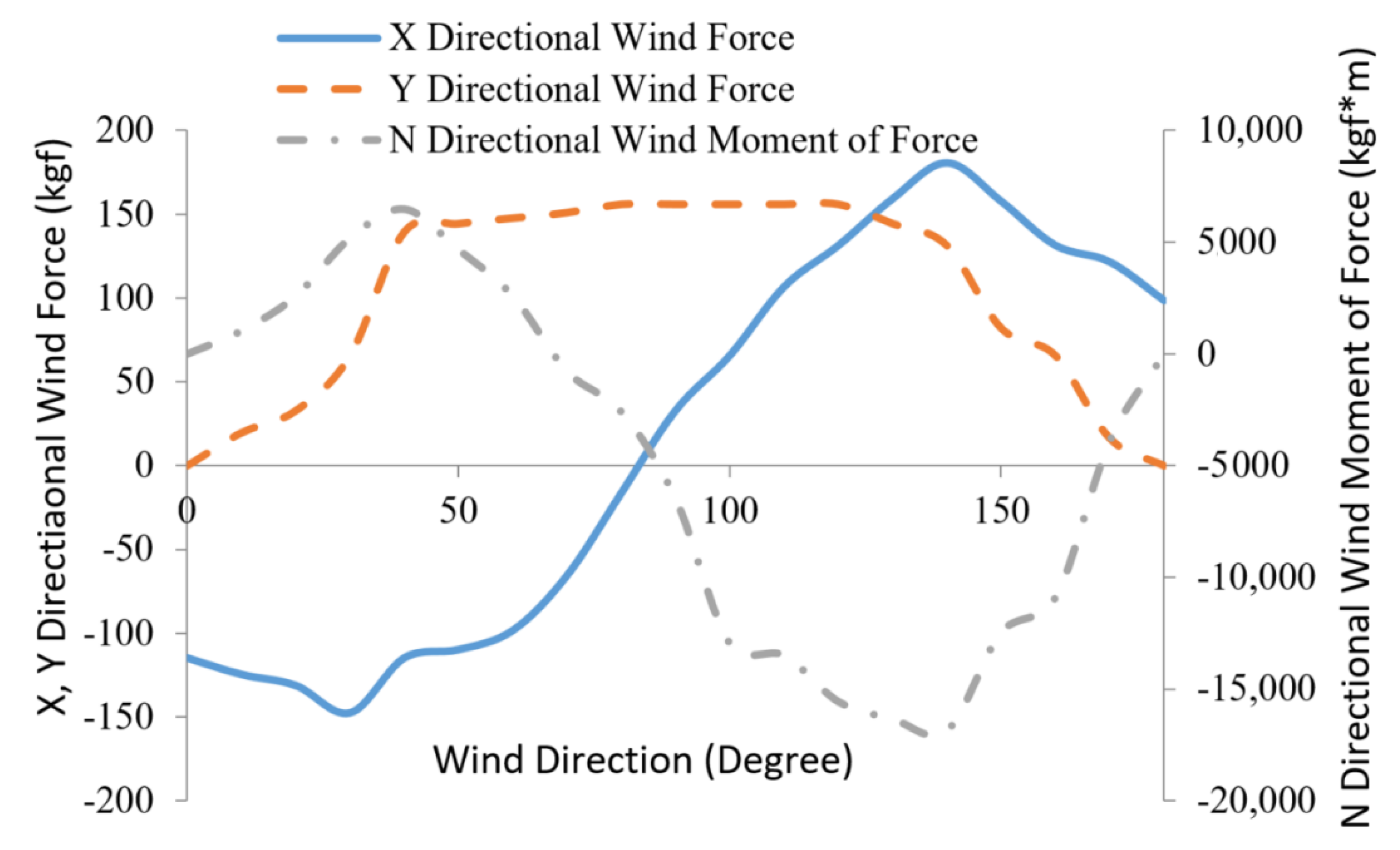
, and based on the ship parameters in the previous chapter, carries out digital simulation on the force of the ship under different angles, and determines its specific numerical value. The simulation results are shown in
Figure 12.
In
Figure 12, the specific stress values of the ship in
X and
Y directions can be found in the left main coordinate axis. The right secondary coordinate axis can be found by solving the moment of force in
N direction.
Based on the above parameters of the towing system, this section realizes the simulation experiment of the turning maneuvering of the towing system under the action of wind (10 m/s wind speed and 90° wind direction angle). Through the experiment, we can know the mechanical distribution of the towing system under the action of wind, the coordinated distribution position of the tugboat, the sailing speed of the ship, and the position change of the towing system during the navigation.
According to the simulation results in the
Figure 13, it can be found that the turning process of tug 1 and tug 2 will deviate under the action of wind force, which shows the adverse effect of wind on the turning process of towing. In the turning process, the rudder angle of the whole towing system tends to be consistent. Finally, when the engine of the tugboat is 200 r/min and the rudder angle is 10°, the ship is assisted to complete the turning experiment affected by wind.
Since the ship has no self-propelled ability, the speed difference between the two tugboats is used to realize the normal turning of the ship during the turning process of the towing system. In
Figure 14, it can be found that during the whole turning process, the ship’s speed change trend is consistent with that during longitudinal navigation maneuvering, and the final stability is about 1.001 m/s. Due to the influence of wind force on the towing system, the change of tugboat is more complex. When the ship speed is relatively stable, the speed difference of two tugboats occurs. One part resists the influence of wind force, and the other ensures the success of turning.
In the process of turning the towing system, the difference of the cable force between the two tugboats is caused by the speed difference between the two tugboats. The change trend of the cable force difference between the two tugs is consistent with that of the speed difference between the tug 1 and the tug 2 in
Figure 15. Affected by the wind force, the change of the cable force in this process is more complicated.
5. Digital Simulation of Multi-Tugs Towing a Ship in the Port Environment
Based on the research of the multi-tug longitudinal towing and slewing towing in the previous chapter, it can be seen that the establishment of the mathematical model of the ship is feasible. Therefore, this section describes a systematic digital simulation of towing for multi-tug auxiliary towing. Using Visio studio simulation technology software, the electronic chart of Rizhao Port is used as a digital simulation map. The whole process is that the multi tug auxiliary ship approaches the berth. For a better understanding, the specific process can be seen in the
Figure 16.
In this section, the tugboat-assisted ship towing movement is realized. During this process, not only can the speed and angle changes of the towing system be observed, but also the technical distribution of the tugboat and the position change of the tugboat in the tugboat system. The specific change process is as shown in
Figure 16.
During the whole movement process, the tugboat assists the ship’s longitudinal navigation and steering movement. The speed of the ship’s movement is assisted by the tugboat. In the initial stage of the movement, the speed is slow and the direct navigation state is maintained, as shown in
Figure 17. The engine speed of the tugboat is maintained at 100 r/min, and the speed of the towing system is gradually increased, from a static state to 0.93 m/s, and then stabilized for a period of time at this speed. When the entire system gradually stabilizes, the tug continues to accelerate to increase its engine speed to 260 r/min, and the speed of the towing system gradually increases to 1.24 m/s. This speed is maintained for a period of time to allow the entire towing system to gradually stabilize. When the entire towing system gradually approaches the berth, the tugboat’s speed also gradually decreases, and its engine speed is also reduced from 260 r/min to 200 r/min, and then to 100 r/min after a period of stability, and gradually reduced to 0 r/min. During this process, the speed of the towing system is also dropped from 1.24 m/s to 1.21 m/s, then to 0.87 m/s, and gradually reduced to 0.46 m/s, and dropped to 0 m/s after reaching the designated berth. The speed change process of the entire towing system can be seen in the
Figure 18.
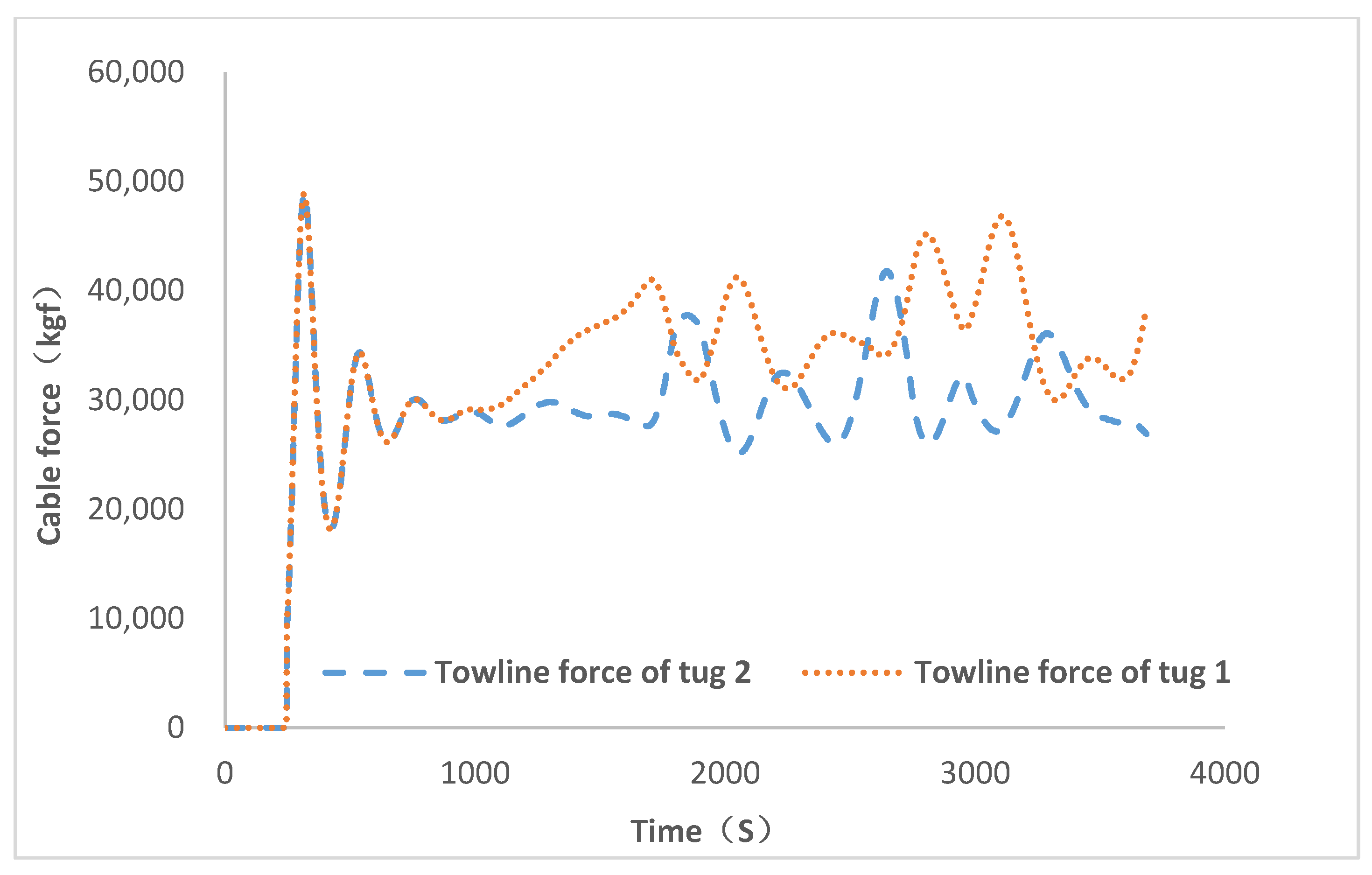
In the movement of a ship with the assistance of a tugboat, the force of the process is transmitted by the rope, so the mechanical changes of the rope are also particularly important. In order to better understand the change process of the above-mentioned cable force, see the
Figure 19.
During the towing process, the change of the rope force will also cause the change of the rope length. The specific change process of the rope length can be seen in the
Figure 20.
In the process of towing movement, the whole movement mainly includes the direct flight and steering of the towing system. In order to better understand the whole process, establish the heading coordinates for the heading of the ship. When the heading is true north, the heading angle is zero degrees. When the heading of the towing system rotates clockwise, it is a positive value; when it rotates counterclockwise, it is a negative value. Therefore, the initial heading of the towing system is
. As it gradually approaches the berth, the heading of the towing system also changes gradually. The process of change can be seen in the
Figure 21.
6. Conclusions
In this paper, two main pieces of research are realized. Firstly, the mathematical model of tugboat-assisted ship maneuvering is completed by digital modeling of the towing system, and the mechanical analysis of the towing system is introduced in detail. Based on the geometric relationship of tugboat assisted ship maneuvering, the force of tugboat assisted maneuvering is completed. In addition, the towing simulation platform of multi-tug-assisted ships is built by using Visual Studio development tools. On the simulation platform, the longitudinal towing simulation experiments of multi-tugs at different speeds are carried out, and the turning towing operation simulation of multi-tugs under the influence of no wind and wind interference is carried out. The simulation results show that with the increase of towing speed, the initial towing speed fluctuates greatly; the wind disturbance force has an obvious drift effect on the ship, and the cable force of the tugboat will fluctuate. The simulation results show that the multi-tugs towing system and simulation platform may be used for the training of the tug’s crew. At the same time, this paper still has shortcomings. For example, it lacks the test of a multi-tugboat towing ship and the comparison with the measurement results of actual tug operation. This is because the towing force is difficult to measure, and the test data for the towing of a multi-tug-assisted vessel cannot be obtained. However, the towing simulation system of the multiple tugs can be used for the training of tug drivers. It can also be used as a simulation verification platform for the automatic berthing of multi-tug auxiliary ships. In our future research work, the interference force of the port environment on the hull during berthing movement will be fully considered, the automatic berthing path will be planned, and automatic berthing control by multi-tugs will be carried out.


