1. Introduction
The marine propulsion shaft of a ship transmits the torque from the main engine to the propeller and delivers the propeller force to push the ship forward [
1]. A proper evaluation of the vibration response for the shaft is essential to guarantee the power transmission and to improve working efficiency. Excessive vibrations will induce an overload during the working of the shaft and cause unpredictable shaft fracture [
2]. Torsional vibration [
3] is attributed to the cyclic torque of the main engine, and longitudinal vibration [
4] is caused by the unsteady thrust of the propeller. The coupling interaction between complex vibration forms seriously threatens the stability of the marine propulsion system and the navigational safety of the ship.
It should be pointed out that the coupled torsional-longitudinal vibrations of the marine propulsion shaft are caused by deflection during shaft rotation. This means that the center line deviates from the axis of the shaft in the process of the shaft’s motion [
5]. Specifically, the piston rod assembly will deviate from the cylinder center caused by the longitudinal displacement, increasing the wear of the piston, thus inducing coupled torsional vibration. Meanwhile, the torsional angle will lead to in-cylinder pressure on the transmission equipment and then induce coupled longitudinal vibration. In virtue of the coupled interaction, the vibration intensity of the shaft will be enlarged and the noise degree of the propulsion system will be increased. Thus, this will lead to the fatigue fracture of the shaft and its relative parts due to the large shear deformation and even to the direct failure of the shaft itself [
6].
Moreover, the cycle pulsation of the main engine, the irregularity of the hull deformation, and the non-uniformity of the propeller work space may cause complex exciting on the shaft. Thus, the shaft will generate different forms of external excitation and then produce a complex dynamic response [
7]. Meanwhile, ships suffer from the wind, waves, and other kinds of excitation during navigation. As a result, the shaft–hull deformation coupled vibrations may be excited and, hence, the shaft responses are enlarged simultaneously [
8]. Therefore, these external and internal excitations will complicate the dynamical response of the marine propulsion shaft. The fracture and failure will be produced because of the overload operation [
9].
As the influence of the coupled vibrations on the marine propulsion shaft has been noticed and realized, studies on the coupled torsional-longitudinal vibrations have gradually developed in recent years. Therefore, a large number of research works have investigated the reduction and control of the coupled vibration of the shaft, based on a brief review of some of the key papers. In addition to theoretical analysis, numerical calculations and practical techniques have been proposed for the prediction of coupled vibrations. Moreover, some of them focus on shaft vibrations in laboratory experiments on the platform and shipboard measurements during sea trials [
10]. Among this research, impact factors include the length-diameter ratio [
11], coupling stiffness coefficients [
12], damping characteristics [
13], rotational speed, and incentive loads [
14]. Their effects on coupled vibrations are analyzed in this study.
The abovementioned factors influence the coupled torsional-longitudinal vibrations of the marine propulsion shaft. Researchers have investigated a large number of analytical methods, such as the energy method [
15], transfer matrix method [
16], finite element method [
17], and wave approach method [
18], to solve these problems. The disadvantage of many of these models is that they have less flexibility to deal with the coupled model, including the length-diameter ratio, the coupling stiffness coefficients, and the damping coefficients, simultaneously. Moreover, the simplified method has been applied to model the multi-segment and variable cross-section shaft as an integral straight beam. It separates the internal connection and cannot describe the actual operation condition of the shaft. Thus, a suitable method has to be able to evaluate these impact factors and be applicable for the numerical calculation of the practical structure. In view of this, the lumped-mass method is, thus, preferable in this exploration, from which a good estimation can be obtained, addressing the abovementioned impact factors that have received little attention from traditional methods.
In this paper, the investigation of the lumped-mass method, which focuses on the coupled torsional-longitudinal vibrations of the marine propulsion shaft, is numerically conducted. The accuracy and applicability of the lumped-mass model is validated with the theoretical solution. A feasible numerical calculation regarding the bifurcation frequency, the Poincare surface, and the transient response is presented. The influence of the impact factors, including the length-diameter ratio, coupling stiffness coefficient, and damping coefficient on the coupled vibrations, are discussed through comparisons. The appropriate values for a model parameter are thus concluded to develop a numerical methodology applied in the theoretical analysis. A practicable tool for the optimal design of the shaft regarding the coupled vibrations is proposed.
2. Theoretical Basis
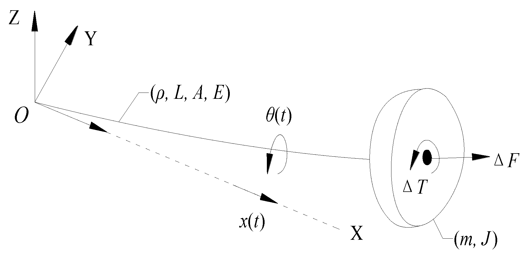
The marine propulsion shaft is simplified and modeled as an Euler cantilever beam with the mass center deviated from the principal axis along the beam, as shown in
Figure 1 [
19]. As an effect of this slight deviation during the shaft rotation, the torsional distortion produces longitudinal contraction with the excitation of external torque. This longitudinal contraction occurs with the torsional rotation and achieves its largest value with the maximal torsional distortion. The shaft changes to its original length as it returns to the initial position. As the torsional distortion produces longitudinal contraction every cycle motion, the longitudinal vibration is thus induced and coupled out. That is the law of motion and dynamical interaction of the coupled torsional-longitudinal vibrations of the rotational shaft. References [
20,
21,
22] have demonstrated the accuracy of the theoretical analysis for a marine propulsion shaft.
The longitudinal virtual force
caused by equivalent torsional distortion and the torsional virtual torque
caused by equivalent longitudinal contraction during the shaft rotation are defined as follows:
where
and
are the coupled longitudinal–torsional stiffness and coupled torsional-longitudinal stiffness, respectively. The
and
are the torsional and longitudinal deformation of the shaft, respectively.
Thus, we define the longitudinal virtual force
and the torsional virtual torque
as the external excitations for the vibration equation. On the theoretical basis of the free vibration, the coupled torsional-longitudinal vibrations (or coupled vibrations for short) of the marine propulsion shaft can be described as:
where
J and
m are the moment of inertia of the principal axis and the mass of the shaft, respectively. The
and
are the torsional damping and stiffness, respectively. Similarly, the longitudinal damping and stiffness are denoted by
and
. The
and
are the rotational speed and the time. The parameters
and
with the coupled stiffness coefficient
are defined as:
where the inertia coupling
is defined on the basis of the hydrodynamic force to
and the moment to
[
5]. The value of the coefficient
is considered to be smaller than 0.10 with the investigation of shaft experiments, shown in
Figure 2 [
20]; calculation results with values of 0.06, 0.02, and 0.008 have been compared for the coupled vibrations in [
23]. As the value definition has not been explained in detail, the value of
is thus defined for the initial numerical calculation, and a suitable value will be discussed in the following section.
The natural frequencies of the above coupled equation sets (2) can be described as the following formula without considering the damping:
It can be seen that no coupling effect exists with . The value of is and , which is the natural frequency of the individual torsional and longitudinal vibration, respectively. The natural frequencies of the vibrations will be mutually coupled and interact with .
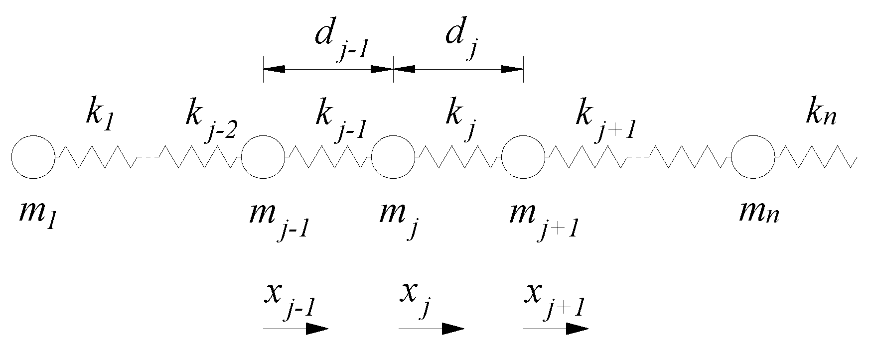
The lumped-mass method is introduced to investigate the coupled torsional-longitudinal vibrations for the shaft as a characteristic of the multi-segmented and variable cross-section [
24]. The proposed method can model the geometrical dimension and operation condition of the shaft more closely to reality. Thus, the marine propulsion shaft can be simplified as multiple lumped masses, as shown in
Figure 3.
As the shaft is simplified to several parts with the proposed lumped-mass method, Equation (2) for the coupled torsional-longitudinal vibrations can thus be rewritten to represent every part (mass
) of the shaft, as follows:
The matrix of moment of inertia
and the mass matrix
of the shaft are, respectively:
where the parameters
Jj are defined as:
where the parameters
mj and
rj are the mass and diameter of each part of the shaft.
The torsional and longitudinal damping matrix
and
are:
where the damping parameters
and
are defined as:
where the torsional and longitudinal damping coefficient are
and
[
23].
Similarly, the torsional stiffness matrix
and the longitudinal stiffness matrix
are:
where the stiffness parameters
and
are described by the following formula:
where
and
are the shear modulus and the elastic modulus of the shaft, respectively. For the structure with a circular cross-section, the second polar moment of area is
and the second axial moment of area is
. The shaft length of each part is
. The sectional area for each part of the shaft can be calculated by
; thus, the mass of each part of the shaft is defined as
.
The coupled stiffness matrix
and
can be described as:
The torsional angle and longitudinal deformation matrix are and with the and being the components of the relative matrix.
3. Verification
The verification of the lumped-mass model for generating accurate results is undertaken through a comparison with the theoretical solution, taking the example of a shaft platform. The shaft in the numerical model is considered in a free running condition without the propeller and is oriented horizontally with the keel line to keep consistent with the platform. The model parameters are defined in the same way as the shaft platform. The stiffness, damping and other mechanical characters are defined from Equations (5)–(12) in the theoretical model. The parameters of the shaft are GPa, GPa and Kg/m3. Moreover, the lengths of each shaft segment are m, m and m, and the diameters are m, m and m, from the fixed end to the free end, respectively. Moreover, the torque and longitudinal force with the rotational speed of 100 rpm are N·m and kN.
To define the calculation length, the solving time is 1 second to represent the numerical results. The initial state of the shaft is set as and . During the comparison of the proposed lumped-mass model and the theoretical solution, the coupling stiffness coefficient is not considered to maintain consistency. That means that the coupled stiffness is assumed as to analyze the individual torsional and longitudinal vibration responses.
In the lumped-mass model, a numerical calculation using MATLAB (Natick, MA, America) with the high-order Runge–Kutta algorithm is employed to calculate the vibration behavior of the shaft.
In the theoretical solution, the theoretical results can be described according to the following formula according to the dynamical theory of a cantilever beam [
25]:
where
,
,
and
. All the parameters of the shaft are introduced in the theoretical basis. The longitudinal deformation
x will be solved. Similarly, when
,
,
and
, the torsional angle
θ will be solved.
Thus, the torsional angle
θ and longitudinal displacement
x are, respectively, obtained with the lumped-mass model and the theoretical solution.
Figure 4 is the comparison of the dynamical response for both methods during one second. The results show that the torsional amplitudes are
rad and
rad, and the maximal longitudinal deformations are
m and
m with the lumped-mass model and theoretical solution, respectively. The comparisons show that the lumped-mass model generates results which are well consistent with the theoretical formulations. The highest deviation around the maxima may be caused by the shaft division in the lumped-mass model, which is not unexpected since the theoretical solution does not take this into account. The proposed lumped-mass method is, thus, proved to be accurate as the error level is very small and acceptable.
4. Numerical Calculation
As the theoretical basis indicates that the coupling stiffness coefficient induces the coupled torsional-longitudinal vibrations of the shaft, Equation (5) indicates an influence of the structural dimensions and damping effect on the shaft dynamical response. Along with the lumped-mass method being proved to be suitable and applicable to calculate the coupled vibrations for the marine propulsion shaft, the numerical calculations focusing on the impact factors including the length-diameter ratio, coupling coefficient and damping coefficient are therefore conducted with the proposed lumped-mass method. On this basis, the dynamical responses with the above impact factors are numerically obtained and compared. The influence on the coupled vibrations of the shaft is thus investigated and determined.
The numerical results including the bifurcation diagram, the Poincare surface and the transient response will be determined. The bifurcation diagram indicates the bifurcation frequency that should be designed to be reduced and even avoided for the structure. The Poincare surface including the displacement and velocity is used to describe the axial orbit of the cross-section during shaft rotation. The purpose of the transient response is to predict the ultimate rotational angle and longitudinal displacement. Thus, the dynamical responses of the coupled vibration for three specific cases regarding the length-diameter ratio, coupling stiffness coefficient and damping coefficient are compared in this section.
4.1. Effect of the Length-Diameter Ratio
As the geometrical dimension of the marine propulsion shaft has significant importance for the dynamic characteristic and control algorithms, the influence of structural parameters on the coupled vibrations needs to be discussed. Defining the length ratio as and the diameter ratio as , the length-diameter ratio can be expressed by . The initial values of the aforementioned numerical model are . In addition, other mechanical parameters for the lumped-mass model are kept unchanged during the numerical calculation. The influence of the length-diameter ratio on the coupled vibrations can be analyzed by changing the values of parameters and , respectively. Thus, the numerical results of various length-diameter ratios can be obtained for the comparison.
The results in
Figure 5 are the bifurcation diagram of the coupled vibrations with the length ratio increasing from 0.5 to 2.0 and a diameter ratio of
. The bifurcation frequencies of the coupled vibrations in both directions can be found to decrease with the increasing length ratio. The torsional bifurcation frequency ranges from about 47 to 23 and then to 12 rpm, while that for longitudinal direction ranges from about 83 to 41 and then to 21 rpm. The trend of the variety is nearly reduced by several times, over a range of multiple length ratios. Moreover, all three cases of longitudinal bifurcations show a smaller peak corresponding to coupled torsional bifurcation. Although the torsional bifurcation does not show a smaller coupled bifurcation clearly, a weak bifurcation caused by the coupling effect still appeared in the case of
and
. Meanwhile, the displacement of the natural bifurcation regarding the ordinates is much greater than that of the coupled bifurcation. That is, the displacement of torsional bifurcation is larger than that of the coupled torsional bifurcation caused by the longitudinal vibration, and vice versa. It should be concluded that the interaction of the coupled vibrations will affect the bifurcation frequency in an individual direction as well as the coupled direction.
Similarly, the bifurcation diagram of the coupled response with the length ratio
and the diameter ratio increasing from 0.5 to 2.0 is shown in
Figure 6. The bifurcation seems unchanged with the increasing diameter ratio for the coupled vibrations. It can be concluded that the bifurcation frequencies are independent of the diameter of the shaft. Moreover, the longitudinal bifurcation with
shows a smaller peak corresponding to coupled torsional bifurcation. That means that the interaction is still existent for the frequency domain of the coupled vibrations. The bifurcation frequency in the coupled direction should be considered for the minimization of the dynamical response, while the displacement regarding the ordinates at each bifurcation decreases severely with the diameter increasing by several times. This means that the diameter ratio of the shaft determines the transient severity of the coupled vibrations.
As with the influence of the coupled interaction, the shape of the axial orbit for both directions is not a regular circle.
Figure 7 shows the Poincare surface of the coupled vibrations with various length-diameter ratios. For the case of the length ratio increasing from 0.5 to 2.0 and a diameter ratio of
, the Poincare surface of both directions gradually increases. The variety of the axial orbit is basically doubled as the diameter ratio increases from 0.5 to 1.0, and then to 2.0. Similar results can be found in the longitudinal Poincare surface, which means that the variety is basically doubled as the length ratio increases several times. Thus, it can be seen that the increase of the Poincare surface of the coupled vibrations is multiplied as the variety of the length ratio increases.
The axial orbits decrease for the case of a length ratio of and the diameter ratio increasing from 0.5 to 2.0; as the diameter increases, the effect on the motion regularity is more obvious and the disparity between two adjacent cases is more striking. The variety of the Poincare surface is much larger than the multiple ratio. That means that the diameter ratio affects the torsional Poincare surface significantly, similar to that of the longitudinal direction of coupled vibrations. Therefore, it can be concluded that the length-diameter ratio has a significant influence on the Poincare surface of the coupled vibrations, especially the effect of the diameter ratio.
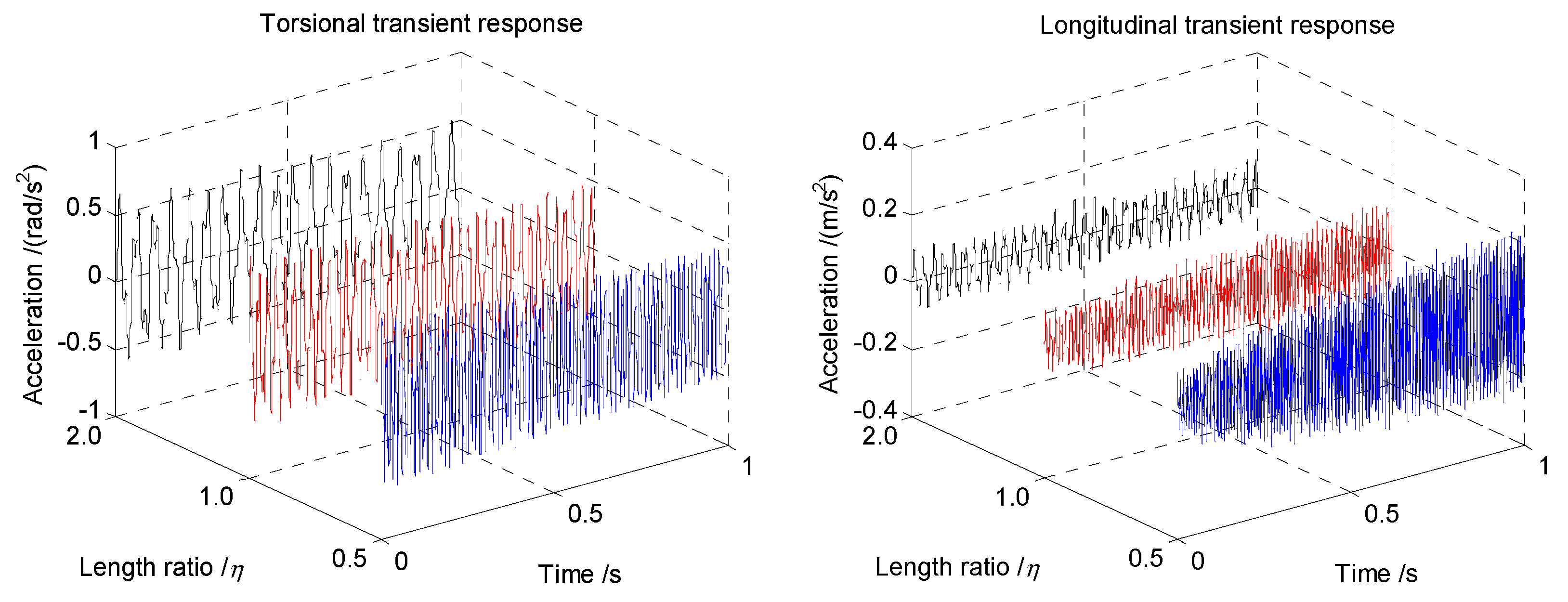
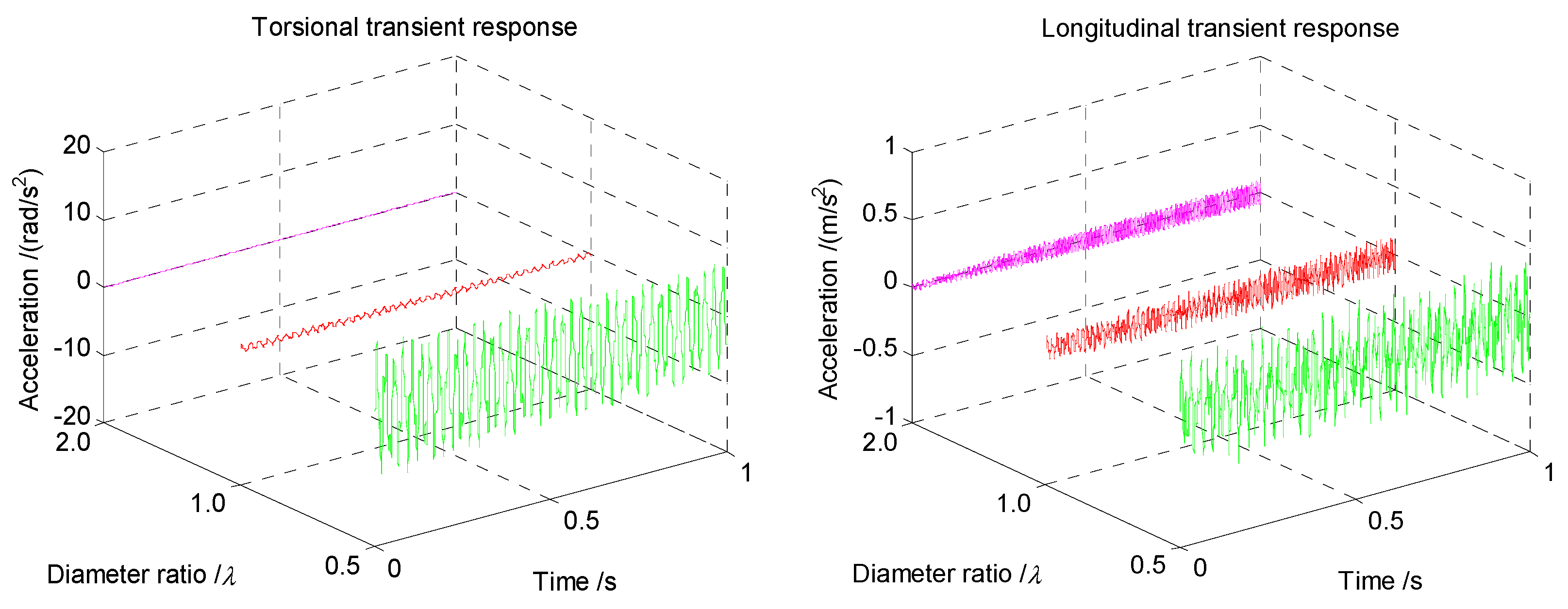
Figure 8 indicates the transient response of the coupled vibrations with various length ratios. It is shown that the torsional accelerations basically remain unchanged with the length ratio ranging from
to
and then to
. However, a slight decrease can still be found with the length ratio increasing. However, the variety in the longitudinal transient response is much more obvious than that of the torsional direction. The longitudinal acceleration decreases several times with a value of nearly the ratio of the shaft length. Thus, a reciprocal relationship regarding the length ratio can be obtained for the shaft length and the longitudinal transient response.
The transient response of the coupled vibrations with increasing diameter ratio is shown in the following
Figure 9. It can be found that the coupled accelerations display a huge decline with the shaft diameter increasing several times, and the variety between different cases is significant, especially for the case of
. The coupled accelerations are much greater than that of
and
, as shown in
Figure 9. A non-linear relationship for the coupled accelerations and diameter can, thus, be concluded.
4.2. Effect of Coupling Stiffness Coefficient
The theoretical basis indicates that the coupled torsional-longitudinal vibrations are caused by the coupling stiffness coefficient. The definition of the coefficient
is based on experiments, and the value range is concluded in
Figure 2 of the theoretical basis. Therefore, a comparison on the basis of various coefficients of
for the optimum solution can be applied for the determination of the value. Considering that the maximal value of the coefficient
δ should be smaller than 0.10, the values of 0.01 and 0.04 are thus defined and then compared with the results of the initial value 0.02. Therefore, defining the coupling stiffness coefficient ratio to be
and the initial parameters of the aforementioned numerical model to be
, the value definition of the coupling stiffness coefficient is, thus, formed and the influence on the coupled vibrations of the shaft is investigated. As the bifurcation diagram is independent from the coupling and damping coefficients, only the Poincare surface and transient response are considered in the following sections.
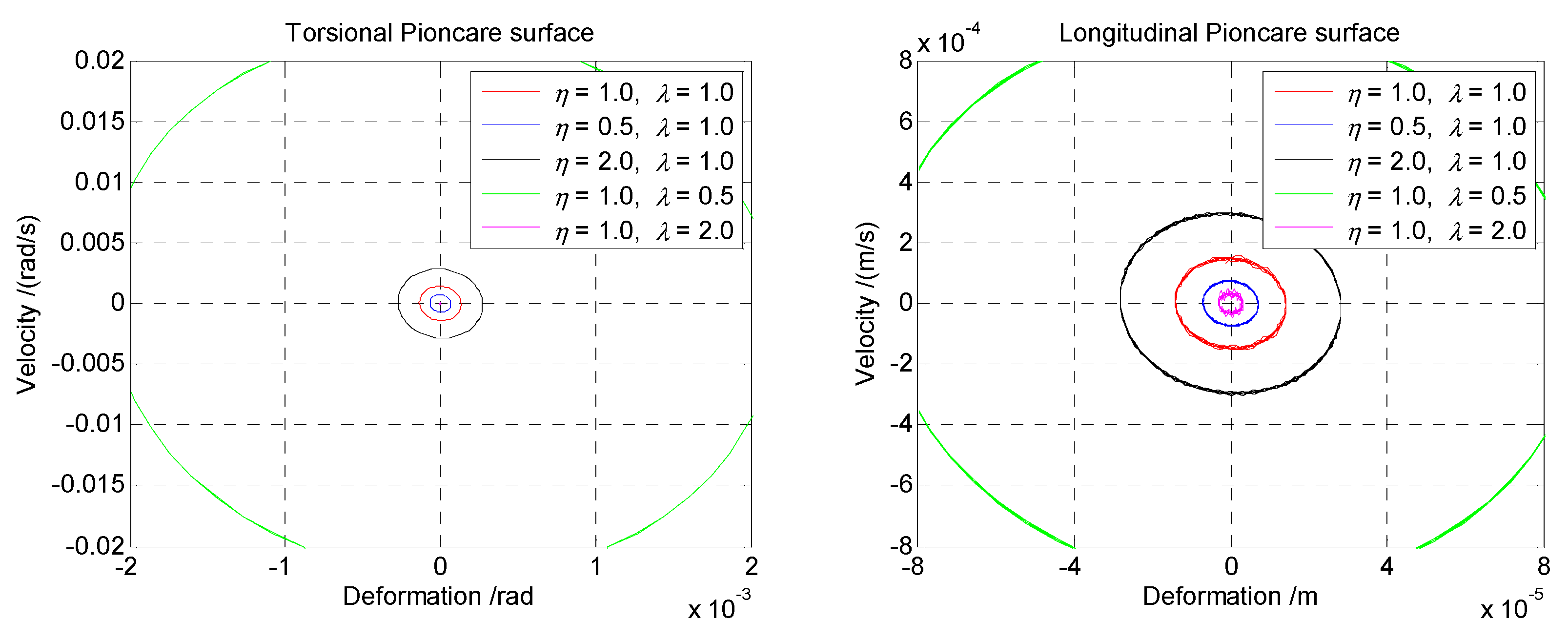
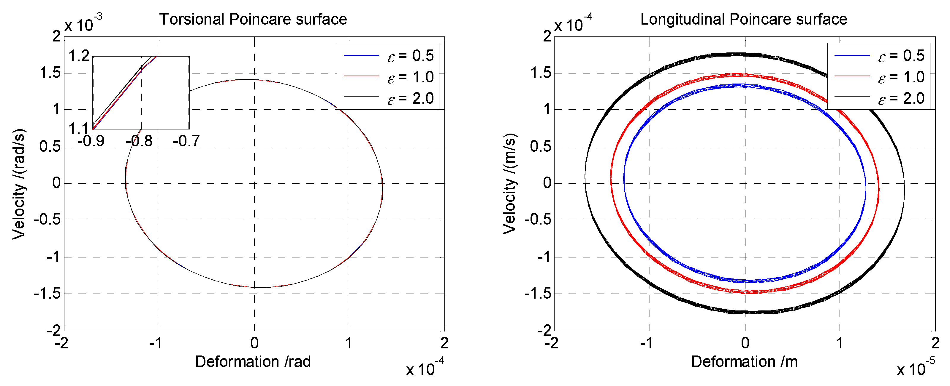
Figure 10 is the Poincare surface of the cross-section of various coupling stiffness coefficient ratios of the coupled torsional-longitudinal vibrations. As the shape of the axial orbits is close to an ellipse, this indicates the existence of an interaction for the coupled vibrations. Specifically, the torsional Poincare surface response is in a nearly steady state according to the discretization between each periodic, especially for the comparison between the case of
and
. This trend of sectional motion is nearly independent from the coupling stiffness coefficients. However, the longitudinal Poincare surface appears to be a serious variety when the coupling stiffness coefficient increases. The axial orbit of
is much larger than that for the case of
and then that of
. Moreover, this increase for each case of the coupling stiffness coefficient is not a multiple or linear relationship.
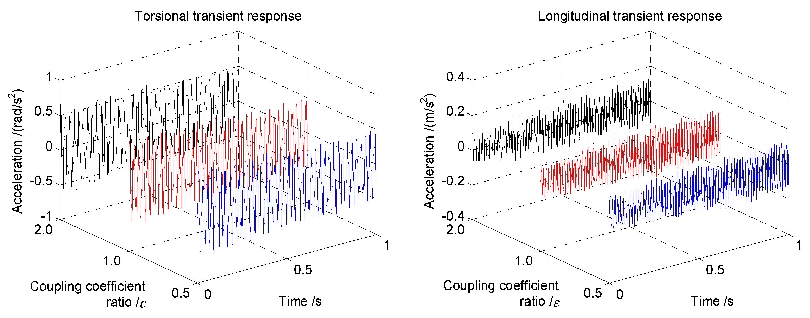
For the transient response with various coupling stiffness coefficients in
Figure 11, the acceleration variety basically reduces as the coupling stiffness coefficients increases. That means that the coupling stiffness coefficient has little influence on the transient accelerations of the coupled vibrations. However, the behavior indicates a slight increase with the coupling stiffness coefficients range from
to
based on the comparison. It should be pointed out that the transient response of torsional direction changes slightly, while the longitudinal curves show an obvious variety with increasing coupling stiffness coefficients. Therefore, the coupling stiffness coefficients should be considered in the incipient design process for the shaft.
4.3. Effect of Damping Coefficients
The damping coefficients defined in Equation (9) are based on an empirical formula and experimental measurement. While the definition of the damping coefficients has not been explained in detail, as the damping impact is indispensable during shaft rotation, the friction of the bearings and the rotational speed may also cause the variety of the shaft damping. According to the initial damping coefficients and the limit of the value, the torsional and longitudinal damping coefficients are defined as
and
, respectively [
26]. The torsional damping ratio is defined as
and the longitudinal damping ratio as
in this section. Therefore, the damping ratio
,
and the
,
are, respectively, defined in the numerical model. Thus, various values of coefficients are investigated for comparison and discussion to determine their influence on coupled vibrations.
For the case of torsional and longitudinal damping ratios, the Poincare surface of the section is shown in
Figure 12. The motion tends to be oblate circular under the effect of coupling interaction, as in the previous cases. The Poincare surfaces of both directions are in a nearly steady state according to the discretization of various damping ratios. Additionally, the periodic motion of torsional direction is comparatively steadier than that of the longitudinal direction. It can be found that the damping affects the Poincare surface of the coupled vibrations slightly.
Figure 13 and
Figure 14 are the comparison of the transient response with various torsional and longitudinal damping coefficients, respectively. For the case of torsional damping ratio, the coupled accelerations show a slight decrease in torsional direction and unchanged curves for the longitudinal acceleration. Similarly, for the case of the longitudinal damping ratio, the transient results of the coupled vibrations are nearly unaffected with a slight decrease in longitudinal acceleration. This means that the damping affects the transient response in its direction more obviously than the coupled direction. That is, the torsional damping coefficient affects the torsional response more severely than the longitudinal response, and vice versa. Although the discretization of the defined damping coefficient ratio is not large enough for comparison, this small variety of the transient response can be still noticed from the longitudinal response in
Figure 13 and the torsional response in
Figure 14, respectively. Hence, the influence of the damping coefficient on the coupled vibrations should not be ignored during the design stage of the shaft.
6. Conclusions
In this paper, the investigation of the lumped-mass method was proposed to study the performance of coupled torsional-longitudinal vibrations for the marine propulsion shaft. Dynamic behaviors including the bifurcation diagram, Poincare surface, and transient response of various model parameters were numerically calculated. The bifurcation frequencies, motion regularity and transient accelerations of the coupled vibrations were numerically investigated. The impact factors including the length-diameter ratio, coupling stiffness coefficient and damping coefficient on the coupled vibrations were thus compared in detail. A more suitable range of the material properties and structural dimensions for the coupled vibrations of the shaft was discussed and presented.
The numerical results of the lumped-mass method were found to agree well with the theoretical solution in the verification section. It can be concluded that the lumped-mass method is suitable and applicable for the coupled torsional-longitudinal vibrations of the shaft. To address these issues, further investigation focusing on the length-diameter ratio, coupling stiffness coefficient, and damping coefficient was conducted. The results of the bifurcation diagram indicated that the coupled frequencies are closely related to the geometric dimensions of the shaft; the coupling interaction for the frequencies can be found from the bifurcation diagram. The Poincare surface showed that the motion regularity is less stable with the increasing the length ratio and coupling stiffness coefficient, while it is more stable when the diameter ratio increases. It can be found from the transient response that the maximal accelerations decrease with the increasing length ratio and diameter ratio. The same goes for the increasing coupling stiffness coefficient and damping coefficient with a relatively small variety of accelerations. According to the comparison and discussion, the range for the length-diameter ratio, coupling stiffness coefficient and damping coefficient should be considered as more appropriate to represent the coupled vibrations of the marine propulsion shaft. Further work is needed to investigate the influence of oil films, bearing supports and other impact factors of coupled torsional-longitudinal vibrations.


