Abstract
To address the sideslip phenomenon caused by the lack of lateral constraints in path following of underactuated hovercraft, this paper proposes a path following control algorithm. The algorithm adopts a method of controlling two control points on the underactuated hovercraft, in which the first control point ensures position tracking accuracy while the second point decreases the sideslip angle. To further decrease the sideslip effects during turning maneuvers, a speed regulator based on path curvature radius is designed to adjust the desired speed by balancing centrifugal force and lateral dynamic constraints. Simulation results show that the sideslip angle can be reduced while the position error exponentially converges to zero.
1. Introduction
Hovercraft, with their exceptional amphibious mobility, and high-speed maneuverability, have gained increasing attention in marine engineering operations [1,2]. Such hovercraft are broadly utilized across complex and changing operational scenarios to accomplish multiple objectives like sea rescue operations, research voyages, military reconnaissance, and coastal patrol [3,4,5,6,7,8]. Meanwhile, the expanding operational scope and growing mission complexity demand higher accuracy and reliability in control system development. Hovercraft control necessitates both the convergence of position errors to a precisely bounded range and the satisfaction of stringent attitude control requirements.
Hovercraft employ air cushion support for suspended navigation. Lacking lateral constraint devices such as underwater rudder surfaces found in traditional vessels, they typically possess only two control inputs: surge force and yaw moment. Consequently, the number of control inputs is smaller than the system’s motion degrees of freedom, creating an underactuated dynamic system [9,10,11,12]. Due to the inability to directly control lateral motion, hovercraft are prone to lateral drift under external disturbances when performing path following tasks. The sideslip phenomenon is prevalent in underactuated surface vessels [13]. Reference [14] addresses the sideslip problem of underactuated unmanned surface vessels, pointing out that the sideslip phenomenon caused by uncontrollable non-zero lateral velocity causes difficulties for tasks requiring high attitude accuracy, leading to inconsistency between the hull’s longitudinal axis and the actual trajectory direction. This phenomenon becomes more evident when the craft exhibits high angular velocity, insufficient lateral damping, and significant mass. When a hovercraft has high navigation speed, low lateral damping, or strong external interference, this phenomenon becomes more evident [15].
The impact of the lateral slip behavior on hovercraft path following control accuracy has become an important research topic. Path following control aims to design appropriate control forces and moments to follow a time-independent path, which can be either predefined manually or created through planning algorithms such as the rapidly exploring random tree algorithm [16] and the a-star algorithm [17]. The line-of-sight guidance method [18] is widely used for this purpose. However, the heading deviation induced by the sideslip angle severely degrades guidance performance. To address this issue, researchers have developed extended state observers [19] and compensation strategies [20] to improve tracking accuracy. Nevertheless, these methods only enhance control accuracy when sideslip is present, without actively reducing the sideslip angle itself.
In many situations, hovercraft attitude control is frequently simplified or neglected, with research primarily focusing on trajectory tracking control—ensuring accurate tracking of given reference trajectories [21,22,23,24,25]. This approach essentially implements a two-degree-of-freedom position control strategy. Under this method, the yaw angle remains uncontrolled and varies passively during system operation, leading to a noticeable sideslip phenomenon during curved maneuvers. However, azimuth angle control becomes necessary in specific operational scenarios.
When hovercraft operate in restricted waterways, stringent requirements are imposed on heading control accuracy. The slender, high-aspect-ratio geometry of hovercraft hulls enables optimal spatial utilization when aligned with the waterway centerline, maintaining safe clearance from boundaries. However, excessive sideslip angle deviation increases the effective occupied width, reduces safe standoff distances from both banks, and elevates collision risk substantially.
Full-state underactuated path following control laws [26,27], derived through Lyapunov’s direct method, provide globally bounded following solutions for underactuated hovercraft. However, these methods fail to address the sideslip problem.
Based on the preceding analysis, this paper proposes an underactuated hovercraft path following control algorithm that guarantees uniformly convergent position tracking while reducing sideslip angle through curvature adaptation of the desired path. The key contributions include the following:
(1) A method is proposed that utilizes the two-degree-of-freedom configuration space of underactuated hovercraft for two-point control, one for position control and another for attitude control to reduce sideslip angle.
(2) A speed regulator is designed that dynamically adjusts the forward velocity based on real-time path geometry, effectively decreasing sideslip during curved path following.
The remainder of this paper is organized as follows: Section 2 establishes the mathematical model of the underactuated hovercraft and formulates the sideslip generation mechanism. To address this issue, Section 3 develops a path following control algorithm with rigorous closed-loop stability proof. Section 4 presents numerical simulation validating the controller’s effectiveness. Finally, Section 5 concludes the research.
2. Mathematical Preliminaries and Problem Formulation
2.1. Four-Degree-of-Freedom Hovercraft Model
The traditional three-degree-of-freedom (3-DOF) model (surge, sway, yaw) misses critical roll–sideslip coupling effects, while the six-degree-of-freedom (6-DOF) model (surge, sway, heave, roll, pitch, yaw) adds unnecessary computational complexity. This study proposes a four-degree-of-freedom (4-DOF) model (surge, sway, roll, yaw) that captures essential roll–sideslip coupling while maintaining computational efficiency for optimal path following control. According to Figure 1a, the Earth–fixed coordinate system is defined with an arbitrary point on Earth as the origin O, and the body–fixed coordinate system is defined with the center of mass of the hovercraft as the origin N. The 4-DOF kinematic and kinetic models of the hovercraft are given, respectively, as follows [28]:
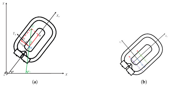
Figure 1.
Symbols: (a) Coordinate system setup. (b) Visualization of and .
The fundamental control objective is to ensure that the hovercraft achieves precise tracking of a -continuous desired path.
where characterizes the desired path.
2.2. Sideslip Angle Issue Analysis
The kinematics of the hovercraft system (1) can be expressed in flow-frame coordinates through reparameterization.
where U is the ground speed and (with the yaw angle, the sideslip angle), satisfying:
where the lateral velocity component is given by , representing the projection of the velocity vector onto the horizontal plane. The resultant speed of the hovercraft is defined as . When neglecting the roll kinetics (that is, setting where ), (5) reduces to the classical 3-DOF hovercraft kinetic equation.
During path following tasks, the hovercraft will asymptotically achieve position tracking, with approaching :
Taking the time derivative of (6) yields:
Substituting (4) into (7) yields:
According to the path following kinetic (8), a constrained relationship exists between the actual course angle and the geometric derivative of the desired path:
During actual navigation, the hovercraft’s intended velocity vector aligns with the tangent direction of the path. When lateral velocity is present, the yaw angle deviates from the direction of the actual motion path by the sideslip angle . This deviation appears visually as the drifting effect, known as lateral slip.
The control objective for reducing lateral slip is to align the hovercraft’s surge direction with the path tangent as closely as possible, while ensuring path following precision.
3. Control Algorithm Design
The present section develops a hierarchical control system for path following of underactuated hovercraft based on the backstepping control method. The controller architecture is depicted in Figure 2. First, the kinematic controller generates virtual velocity commands to guarantee exponential stability of path following errors while decreasing lateral slip through a velocity regulator. Second, the kinetic controller designs control inputs based on the virtual commands to ensure closed-loop stability. The proposed design effectively reduces the influence of the sideslip angle while maintaining tracking performance.
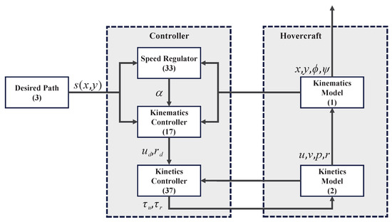
Figure 2.
Block diagram of the proposed control system architecture.
3.1. Kinematic Control with Sideslip Reduction
In the inertial reference frame, two feature points are defined by offsetting the point along the positive and negative directions of the body–fixed frame axis with distance b, which is shown in Figure 1b. The detailed formulas are provided below:
Their coordinate transformation relationship in the inertial frame can be expressed as:
Taking the time derivative of the above equations yields:
The control architecture aims to simultaneously achieve precise path following and effective sideslip angle reduction. The control system employs a two-feature-point design: the primary feature point undertakes the core task of path following, ensuring precise matching between the hovercraft trajectory and the desired path; the auxiliary feature point is specifically responsible for dynamic regulation of the sideslip angle, achieving effective reduction of the hovercraft’s sideslip angle while maintaining path following performance. When is chosen to be sufficiently small, the secant vector formed between the two feature points will converge toward the path’s tangential orientation at an exponential rate.
The error metrics from feature locations to the desired path are defined as:
As and approach zero, and are positioned on the desired path based on (3) . By applying (12), the temporal derivatives of (13) become:
To simplify the notation, the kinematic parameters are expressed as:
Accordingly, (14) becomes:
Based on the preceding analysis, the kinematic control law is formulated as:
therefore, the stability of position tracking error relative to the desired path is achieved, where the positive constant serves as an adjustable gain parameter. This convergence requirement is incorporated as a restriction in the optimization formulation, enforcing the trajectory to strictly satisfy the desired curve constraint, thereby ensuring asymptotic convergence of the pose.
By optimizing the control input to make the system sideslip angle asymptotically converge to zero, its kinetic characteristics are guaranteed by the exponential stability of the error variable . This objective can be transformed into the following optimization problem:
where represents a positive design parameter.
Furthermore, the hovercraft should move along the desired path at a specified velocity instead of merely staying stationary on the curve. To achieve this, a target surge speed is specified. Subject to path following accuracy requirements, we define a speed regulating coefficient to regulate the speed, which will be discussed in detail in Section 3.2. Another optimization objective is to make the actual surge speed u approach .
where is the surge speed regulation gain.
The performance metrics and are formulated as a single objective function with the position convergence control condition serving as the optimization constraint. Based on (16)–(19), the mathematical formulation of this optimization problem is expressed as:
where w represents a positive weighting factor.
Given the performance index J and the constraint g defined in (20), we introduce the Lagrange multiplier to construct the Lagrangian function L as follows:
In the extended parameter space constructed by the Lagrange multiplier , the extremum of the optimization problem is characterized by the following system of equations:
We rewrite (22) in compact form:
where
There exists a solution of (23) expressible as:
where , indicate the desired surge and yaw velocity commands.
3.2. Path Curvature-Based Speed Regulation
For the underactuated hovercraft with only two control inputs, one is used for path following, while the other must simultaneously set the target surge speed and control attitude, and these two tasks cannot be satisfied simultaneously. Given that the core objective is to reduce sideslip angle rather than maintain fixed speed, a speed regulation mechanism is designed to alleviate the conflict. When the curvature radius decreases, the speed is adjusted to provide more control margin for attitude control, achieving better sideslip angle reduction performance.
For the path following problem of underactuated systems, parameterized paths and are introduced. The fundamental cause of sideslip is that the control input dimensions are insufficient to simultaneously satisfy curvature constraints and kinetic requirements, while path geometric characteristics further exacerbate tracking errors. Based on differential geometry theory, we define the curvature radius at coordinates as:
where .
From geometric principles, we derive the fundamental relationship:
Upon convergence of the system state variables, the forward velocity u to and angular velocity r to (2) reduce to:
where and denote the aerodynamic and hydrodynamic lateral damping coefficients, respectively. The total lateral damping represents the comprehensive resistance characteristics of the hovercraft’s sway motion under the combined air–water interface effects.
After applying (29) to , it follows that:
Similarly, when the system reaches steady-state equilibrium, based on (4), it can be derived that:
Taking (28), (30) and (31) as constraint conditions and solving them simultaneously, the following relationship can be obtained:
Based on the above analysis, it can be concluded that reducing the desired speed during turning maneuvers can effectively reduce the sideslip angle. Therefore, this section proposes a control strategy for dynamically adjusting the forward desired speed according to the path curvature radius : when the curvature radius increases (the path approaches a straight line), the hovercraft can increase its speed; conversely, it should reduce speed. Given the curvature radius and the speed adjustment coefficient , we define the mapping relation as:
where is a positive constant.
The implementation process of the hovercraft path following controller is systematically presented in Algorithm 1, while Algorithm 2 provides detailed procedures for path curvature-based speed regulation.
| Algorithm 1 Hovercraft path following algorithm |
|
| Algorithm 2 Speed regulator algorithm |
|
3.3. Kinetic Control Law Design
Within the control loop, velocity errors represent the deviation between commanded and actual motion states.
The kinematic controller’s virtual velocity command yields the feedback-controlled dynamics:
The velocity error system can be described in differential form as:
Taking into account the kinetic characteristics, the control laws are designed as:
where , are positive definite control gains, and the key coupling coefficient contains the roll angle influence:
the terms in represent the roll–sideslip coupling that is unique to hovercraft systems. Unlike conventional marine vehicles where roll effects are negligible (, ), hovercraft experience significant roll-induced lateral motion due to their air cushion support mechanism. This fundamental difference necessitates the inclusion of roll dynamics in the control design, distinguishing this work from traditional 3-DOF approaches such as reference [14].
3.4. Stability Analysis
The stability of the system is analysed by the following theorem:
Theorem 1.
For the closed-loop dynamic system formed by the underactuated hovercraft models (1) and (2) under the action of control laws (26) and (37) and speed regulator (33), the path following error maintains bounded stability, converging to a compact set around the origin.
Proof.
By substituting the control law (37) into the system kinetics (36), the closed-loop kinetics become:
Consider the following Lyapunov function:
where contains the roll angle coupling through the kinematic relationship. Specifically, the path following error inherently includes the roll angle effects via the feature point coordinates defined in (11). This ensures that the stability proof inherently captures the roll–sideslip interaction that is fundamental to hovercraft dynamics.
Differentiating the above expression with respect to time gives:
Therefore, the closed-loop system realizes uniform ultimate global exponential stability in the Lyapunov sense, with error variables , , and converging to the equilibrium point. The proof of Theorem 1 is complete. □
4. Simulation
To assess the efficacy of the designed control algorithm, numerical simulation is conducted.
To thoroughly assess the robustness and performance of the controller under various operating conditions, three distinct case studies are designed and implemented. The first case serves as the baseline scenario, with initial states set to , , a yaw angle , a roll angle , and all initial velocities—surge velocity , sway velocity , roll rate , and yaw rate —set to zero. This original configuration provides a reference for subsequent comparisons.The second case investigates the effect of variations in initial attitude by maintaining the same initial conditions as the baseline except for an increased roll angle of . This scenario is intended to evaluate the controller’s sensitivity to changes in initial orientation. The third case introduces a non-zero initial surge velocity, specifically , while keeping all other initial states consistent with Case 1. This allows an examination of the controller’s behavior under dynamic initial motion conditions. The simulation is executed over a total time of s with a fixed integration step size of s.
For control parameters, the waypoint distance is 0.1 m, and the desired speed is . Convergence gains are selected as and . Control gains include and , while the curvature radius parameter is .
To demonstrate the broader applicability of the control algorithm, path tracking results for complex trajectories such as S-curves are presented. However, the detailed analysis focuses primarily on parabolic paths. As illustrated in Figure 3 and Figure 4, the hovercraft successfully maintains stable tracking of the desired trajectory throughout the entire operational envelope, with results presented in the inertial coordinate frame.
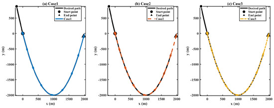
Figure 3.
Path following curve.
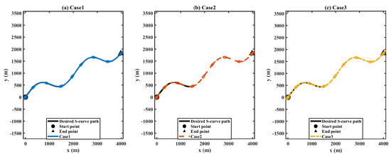
Figure 4.
S-curve path following trajectory.
As shown in Figure 5, the path following position error exhibits stable convergence characteristics over time. The error curve demonstrates a smooth decay process and eventually reaches a steady state. This response behavior verifies the global asymptotic stability of the closed-loop system, with the convergence characteristics matching the theoretically designed expectations.
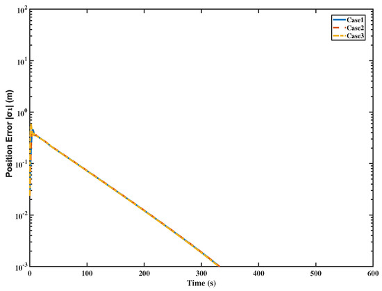
Figure 5.
Path following error.
As shown in Figure 6, the proposed control algorithm demonstrates significant advantages over traditional LOS guidance in sideslip angle management. While the traditional LOS guidance exhibits severe sideslip angle deterioration, dropping to approximately −60° to −70° after 500 s, the proposed algorithm maintains excellent sideslip control throughout the entire navigation process. During straight-line navigation, the proposed method keeps the sideslip angle stable within ±0.5°, and even during turning maneuvers, it only reaches a maximum of −3°. This represents a dramatic improvement over the traditional approach, where large sideslip angles can compromise both navigation accuracy and vehicle stability. The coordinated action of dynamic speed regulation and attitude control in the proposed algorithm achieves superior sideslip reduction while maintaining precise path following performance, demonstrating clear superiority over conventional LOS guidance methods.
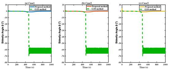
Figure 6.
Sideslip angle variation.
As shown in Figure 7, under the proposed control algorithm, all motion components of the hovercraft exhibit good kinetic characteristics. The surge velocity u rapidly converges to the desired trajectory; the sway velocity v approaches zero after transient adjustment, effectively reducing sideslip; the responses of roll rate p and yaw rate r reflect the coupling characteristics of the 4-DOF model, where r achieves high tracking accuracy for virtual guidance commands. After the system reaches steady state, the errors and fluctuations of all motion parameters remain within engineering acceptable ranges, validating the effectiveness and robustness of the control algorithm.
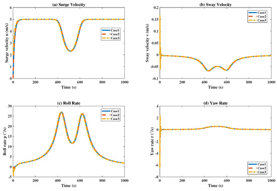
Figure 7.
Hovercraft velocity components.
As shown in Figure 8, it can be observed that the surge force control input rapidly increases during the initial phase and stabilizes smoothly, with the entire regulation process being seamless. The yaw moment control input maintains a stable output throughout the simulation, exhibiting limited variations. Both control signals demonstrate excellent convergence characteristics and stability, with no significant oscillations, indicating that the proposed control algorithm can effectively achieve precise control of the hovercraft.
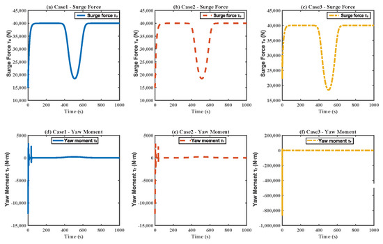
Figure 8.
Control force and control moment.
As shown in Figure 9, it can be observed that the actual speed u starts from an initial zero value, undergoes a smooth ascending process, and successfully converges to the adjusted desired speed after approximately 50 s. The entire response process demonstrates good tracking characteristics without oscillation phenomena. The actual speed can accurately track the desired speed trajectory, validating the effectiveness and stability of the designed control system. From the smoothness of the response curve and the final tracking accuracy, the speed controller possesses good dynamic performance.
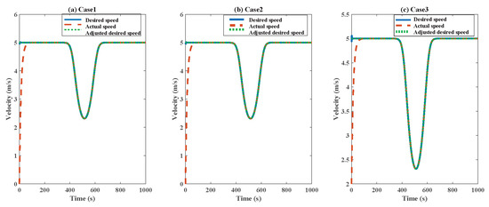
Figure 9.
Speed regulation performance.
Simultaneously, an analysis of the weighting factor is conducted. As shown in Figure 10, Figure 11 and Figure 12, the weighting factor w in the optimization formulation demonstrates a significant influence on system performance characteristics. Smaller values, such as , emphasize path tracking accuracy with minimal following error; medium values, such as , achieve a balanced performance between tracking precision and sideslip suppression; larger values, such as , prioritize speed regulation capability. The comparative analysis reveals that all three configurations maintain satisfactory control performance, while provides the optimal compromise for practical engineering applications, ensuring both tracking accuracy and motion stability within acceptable operational ranges.

Figure 10.
Path following error under different weighting factors w.
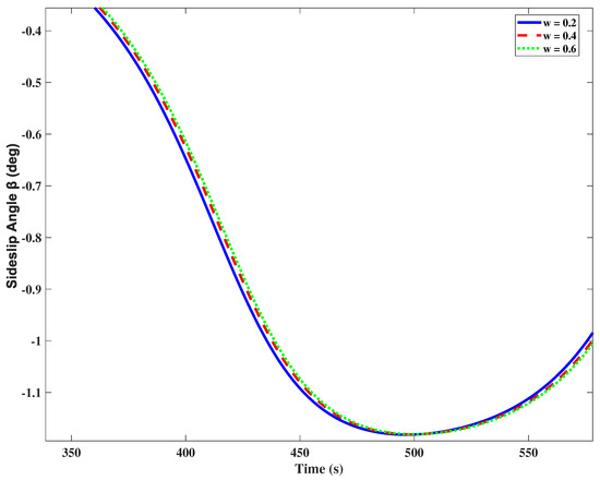
Figure 11.
Sideslip angle variation under different weighting factors w.
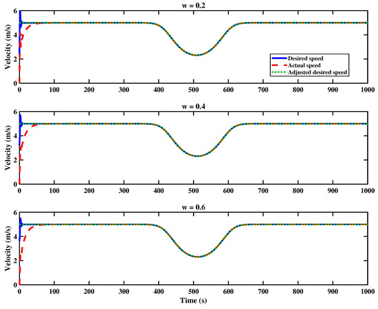
Figure 12.
Speed regulation performance under different weighting factors w.
5. Conclusions
For underactuated hovercraft, attitude control has been relatively difficult due to the limitation of control inputs, making them prone to sideslip phenomena. The proposed path following control algorithm has been developed for underactuated hovercraft, demonstrating its capability in reducing the sideslip angle. The designed controller was approached from a kinematic perspective and has effectively reduced the sideslip phenomenon under the condition of maintained path following precision. Through stability analysis, it has been proved that the constructed closed-loop system is stable. Simulation results have verified the effectiveness of the proposed method in sideslip reduction. Further works will concentrate on secure control because of the requirement of path following for hovercraft subject to cyber-attacks [29,30].
Author Contributions
Conceptualization, R.Y. and W.T.; methodology, R.Y. and W.T.; software, W.T.; validation, R.Y. and W.T.; formal analysis, W.T. and R.Y.; investigation, W.T.; resources, R.Y. and T.L.; data curation, W.T.; writing—original draft preparation, W.T. and R.Y.; writing—review and editing, R.Y. and T.L.; visualization, R.Y. and T.L.; supervision, R.Y. and T.L.; project administration, R.Y. and T.L.; funding acquisition, R.Y. and T.L. All authors have read and agreed to the published version of the manuscript.
Funding
This work was supported by the Dalian Maritime University Applied Research Development Fund (grant number 992005103702).
Institutional Review Board Statement
Not applicable.
Informed Consent Statement
Not applicable.
Data Availability Statement
The original contributions presented in this study are included in the article. Further inquiries can be directed to the corresponding author.
Conflicts of Interest
The authors declare no conflicts of interest.
References
- Xu, S.; Tang, Y.; Chen, K. Numerical investigation on pressure responsiveness properties of the skirt-cushion system of an air cushion vehicle. Int. J. Nav. Archit. Ocean Eng. 2020, 12, 928–942. [Google Scholar] [CrossRef]
- Wang, Y.; Zhou, H. Data-driven constrained reinforcement learning algorithm for path tracking control of hovercraft. Ocean Eng. 2024, 307, 118169. [Google Scholar] [CrossRef]
- Zuo, Z.; Chen, G.; Zhou, X. Analysis of Wave Load Characteristics of Hovercraft Based on Model Test. J. Mar. Sci. Eng. 2024, 12, 1537. [Google Scholar] [CrossRef]
- Kristoffersen, Y.; Hall, J.K. Hovercraft as a Mobile Science Platform Over Sea Ice in the Arctic Ocean. Oceanography 2014, 27, 170–179. [Google Scholar] [CrossRef]
- Liu, R.; Li, X.; Qian, H. Modeling and experimental study of the cushion lift dynamics system of a polar hovercraft. Ocean Eng. 2023, 284, 115246. [Google Scholar] [CrossRef]
- Jin, J.; Zhou, L.; Ding, S. Numerical Simulation of the Ice Breaking Process for Hovercraft. J. Mar. Sci. Eng. 2021, 9, 928. [Google Scholar] [CrossRef]
- Teng, F.; Zhang, X.; Li, T. Distributed resilient energy management for seaport microgrid against stealthy attacks with limited security defense resource. IEEE Trans. Cybern. 2025, 55, 917–926. [Google Scholar] [CrossRef]
- Shan, Q.; Liu, W.; Li, T. A topology reconfiguration strategy for containment control of the multi-USV system based on algebraic connectivity. IEEE Trans. Ind. Electron. 2025, 72, 5322–5332. [Google Scholar] [CrossRef]
- Xie, W.; Cabecinhas, D.; Cunha, R. Robust Motion Control of an Underactuated Hovercraft. IEEE Trans. Control Syst. Technol. 2019, 27, 2195–2208. [Google Scholar] [CrossRef]
- Yan, L.; Ma, B.; Jia, Y. Adaptive Containment Control of Multiple Underactuated Hovercrafts Subjected to Switching and Directed Topologies. IEEE Syst. J. 2023, 17, 3962–3973. [Google Scholar] [CrossRef]
- Su, Y.; Teng, F.; Li, T. Adaptive prescribed-time tracking control for an unmanned surface vehicle considering motor-driven propellers. IEEE Trans. Ind. Inform. 2025, 21, 1665–1673. [Google Scholar] [CrossRef]
- Su, Y.; Teng, F.; Li, T. Fixed-time optimal trajectory tracking control for an electric unmanned surface vehicle via reinforcement learning. IEEE/ASME Trans. Mechatron. 2025. [Google Scholar] [CrossRef]
- Xu, Z.; He, S.; Zhou, W. A Gradient-Based Path Following Control Method for Underactuated Autonomous Marine Vehicle. IEEE J. Ocean. Eng. 2025, 50, 1855–1865. [Google Scholar] [CrossRef]
- Xu, Z.; He, S.; Zhou, W. Path Following Control With Sideslip Reduction for Underactuated Unmanned Surface Vehicles. IEEE Trans. Ind. Electron. 2024, 71, 11039–11047. [Google Scholar] [CrossRef]
- Fu, H. Analysis and consideration on safety of all-lift hovercraft. Ship Boat 2008, 6, 1–3. [Google Scholar]
- Chen, L.; Shan, Y.; Tian, W. A Fast and Efficient Double-Tree RRT*-Like Sampling-Based Planner Applying on Mobile Robotic Systems. IEEE/ASME Trans. Mechatronics 2018, 23, 2568–2578. [Google Scholar] [CrossRef]
- Song, R.; Liu, Y.; Bucknall, R. Smoothed A* algorithm for practical unmanned surface vehicle path planning. Appl. Ocean Res. 2019, 83, 9–20. [Google Scholar] [CrossRef]
- Wang, Y.; Tong, H.; Fu, M. Line-of-sight guidance law for path following of amphibious hovercrafts with big and time-varying sideslip compensation. Ocean Eng. 2019, 172, 531–540. [Google Scholar] [CrossRef]
- Fu, M.; Wang, Q. Safety-Guaranteed, Robust, Nonlinear, Path-Following Control of the Underactuated Hovercraft Based on FTESO. J. Mar. Sci. Eng. 2023, 11, 1235. [Google Scholar] [CrossRef]
- Fu, M.; Zhang, T.; Wang, D. ESO-based line-of-sight guidance law for path following of air cushion vehicle with exact drift angle compensation. In Proceedings of the 2018 IEEE International Conference on Information and Automation (ICIA), Wuyi Mountain, China, 11–13 August 2018; pp. 511–516. [Google Scholar]
- Jeong, S.; Chwa, D. Coupled Multiple Sliding-Mode Control for Robust Trajectory Tracking of Hovercraft With External Disturbances. IEEE Trans. Ind. Electron. 2018, 65, 4103–4113. [Google Scholar] [CrossRef]
- Chaos, D.; Moreno-Salinas, D.; Muñoz-Mansilla, R. Nonlinear Control for Trajectory Tracking of a Nonholonomic RC-Hovercraft with Discrete Inputs. Math. Probl. Eng. 2013, 2013, 589267. [Google Scholar] [CrossRef]
- Chen, X.; Ma, F.; Wu, Y. MFMDepth: MetaFormer-based monocular metric depth estimation for distance measurement in ports. Comput. Ind. Eng. 2025, 207, 111325. [Google Scholar] [CrossRef]
- Chen, X.; Liu, S.; Liu, R.W. Quantifying Arctic oil spilling event risk by integrating an analytic network process and a fuzzy comprehensive evaluation model. Ocean Coast. Manag. 2022, 228, 106326. [Google Scholar] [CrossRef]
- Han, Y.; Liu, X. Higher-order sliding mode control for trajectory tracking of air cushion vehicle. Optik 2016, 127, 2878–2886. [Google Scholar] [CrossRef]
- Aguiar, A.P.; Hespanha, J.P. Trajectory-Tracking and Path-Following of Underactuated Autonomous Vehicles With Parametric Modeling Uncertainty. IEEE Trans. Autom. Control 2007, 52, 1362–1379. [Google Scholar] [CrossRef]
- Dacic, D.B.; Subbotin, M.V.; Kokotovic, P.V. Control Effort Reduction in Tracking Feedback Laws. IEEE Trans. Autom. Control 2006, 51, 1831–1837. [Google Scholar] [CrossRef]
- Fu, M.; Wang, T.; Wang, C. Barrier Lyapunov Function-Based Adaptive Control of an Uncertain Hovercraft with Position and Velocity Constraints. Math. Probl. Eng. 2019, 2019, 1940784. [Google Scholar] [CrossRef]
- Chen, G.; Zhou, Q.; Ren, H.; Li, H. Sensor-fusion-based event-triggered following control for nonlinear autonomous vehicles under sensor attacks. IEEE Trans. Autom. Sci. Eng. 2025, 22, 17411–17420. [Google Scholar] [CrossRef]
- Chen, G.; Zhou, Q.; Li, H.; Yao, D.; Ahn, C.K. Event-triggered state estimation and control for networked nonlinear systems under dynamic sparse attacks. IEEE Trans. Netw. Sci. Eng. 2024, 11, 1947–1958. [Google Scholar] [CrossRef]


Disclaimer/Publisher’s Note: The statements, opinions and data contained in all publications are solely those of the individual author(s) and contributor(s) and not of MDPI and/or the editor(s). MDPI and/or the editor(s) disclaim responsibility for any injury to people or property resulting from any ideas, methods, instructions or products referred to in the content. |
© 2025 by the authors. Licensee MDPI, Basel, Switzerland. This article is an open access article distributed under the terms and conditions of the Creative Commons Attribution (CC BY) license (https://creativecommons.org/licenses/by/4.0/).