Abstract
The deployment of floating offshore wind turbines (FOWTs) in deep, typhoon-prone waters like the South China Sea requires platforms with exceptional stability. However, the performance validation of novel Tension Leg Platform (TLP) concepts under such extreme metocean conditions remains a significant research gap. This study addresses this by numerically evaluating a novel TLP design, including a regular hexagonal topology, a unique bracing structure and heave plates, and an increased ballast-tank height. A coupled numerical framework, integrating potential-flow theory and blade element momentum (BEM) theory within ANSYS-AQWA (2023), was established to simulate the TLP’s dynamic response to combined irregular wave, current, and turbulent wind loads. The resulting time-series data were analyzed using the Continuous Wavelet Transform (CWT) to investigate non-stationary dynamics and capture transient peak loads critical for fatigue sizing, which demonstrated the platform’s superior stability. Under a significant wave height of 11.4 m, the platform’s maximum heave was limited to 0.86 m and its maximum pitch did not exceed 0.3 degrees. Crucially, the maximum tension in the tendons remained below 22% of their minimum breaking load. The primary contribution of this work is the quantitative validation of a novel TLP design’s resilience in an understudied, harsh deep-water environment, confirming the feasibility of the concept and presenting a viable pathway for FOWT deployment in challenging offshore regions.
1. Introduction
Floating offshore wind turbines (FOWTs) are a key technology for accessing the superior wind resources in deep-water sites, where conventional fixed-bottom foundations are not feasible [1]. Techno-economic assessments now demonstrate that FOWTs can achieve a levelized cost of energy competitive with fixed-bottom installations in intermediate and deep-water regimes [2].
FOWTS are generally classified into four main types and these are semi-submersible, spar, barge, and tension leg platform (TLP) [3]. Among these, this platform type is distinguished by its high vertical stiffness and low motions in heave and pitch with a relatively lightweight hull design, yielding superior dynamic performance compared to others [4]. Figure 1 presents six representative concepts: the 8.4 MW S Gamesa turbine was designed by SBM (Amsterdam, Netherlands) [5], the 5 MW reference platform from (Golden, CO, USA), validated by means of prototype testing [6], Bluewater’s modular medium-power design (Gothenburg, Sweden), in service since 2006 [7], MODEC’s scalable version for 10 MW+ turbines (Chuo-ku, Tokyo, Japan) [8], platform (Emeryville, CA, USA), featuring enhanced load-transfer capability for large-scale farms [9], and Germany’s GICON® multi-point tension-leg system, supporting a range of turbine ratings through successive testing phases [10]. These examples highlight the diverse structural approaches and technological pathways being pursued to address the challenges of deep-water floating wind deployment.
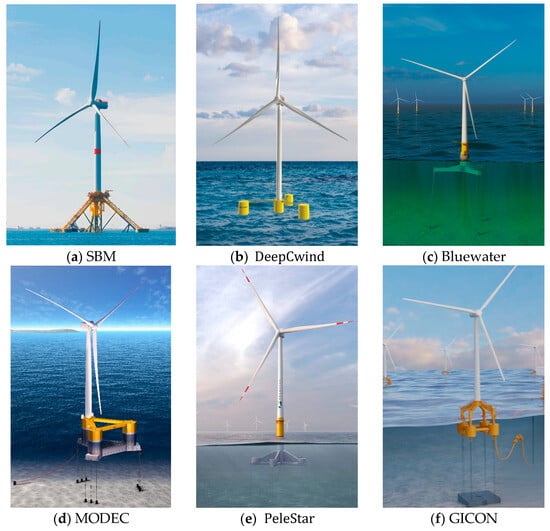
Figure 1.
Schematic of different types of TLP FOWT.
Although TLPs offer superior heave and pitch control and are deployable across a wide range of water depths, their behavior under combined wind, wave and current loading remains highly nonlinear and dynamically coupled. In complex sea states, platform motions feed back into tendon tensions, inducing fatigue damage, amplifying dynamic loads and raising the risk of structural instability. Jia et al. [11] investigated the effects of platform draft and tendon configuration on the dynamic performance of an inclined-leg FOWT. According to [12], tendon specification (material selection, length, diameter and axial stiffness) must strike a balance between high restraint stiffness and favorable dynamic adaptability. The hull form is also critical, as its geometry dictates both hydrodynamic added mass and restoring stiffness [13]. Different design philosophies for the hull have emerged. Single-column concepts, such as DeepCWind [14] and Pelastar [15], face a critical fabrication bottleneck requiring specialized infrastructure. Multi-column topologies like CENTEC [16] and Windstar [17] enhance stability and offer inherent self-stabilization during transport and installation. Truss-type structures with pontoons like the Fully Submersible Platform (FSP) [18] and the SBM design [19] are better suited for mass industrial production, offering a more cost-effective solution. Ma et al. [20] introduced the array to suppress horizontal dynamics via experimental and time-domain simulations. Lefebvre et al. [21] modified the Tri-Floater semi-submersible platform into a tensioned mooring configuration to optimize hydrodynamic response. Shen et al. [22] combined potential-flow theory with the Morison equation to simulate aerodynamic, hydrodynamic, control-system and structural-elastic effects in the time domain, revealing the critical role of nonlinear viscous mechanisms in high-frequency response. Bachynski et al. [23] systematically compared linear and nonlinear behavior across diverse configurations, revealing significant discrepancies in predicted loads and motions when nonlinearities are neglected. Analyzing the effects of wind–wave–current interaction on a 5 MW semi-submersible FOWT, Xue et al. [24] found that neglecting the influence of ocean currents can lead to a significant underestimation of platform motions and mooring loads. In their coupled analysis of the NREL 5 MW FOWT under wind, wave, and current conditions. Wei et al. [25] found that wave loads induce a wave-frequency motion response in the turbine, with wave height and period being the primary drivers of the surge motion. The validation of a fully coupled hydro-aero-elastic analysis [26], conducted using data from 1:50 scale-model tank test of a TLP FOWT prototype, is of great significance for ensuring the structure’s reliability under actual environmental conditions. While various TLP design concepts and analytical methods have been proposed, their reliable deployment in deep-water environments is fundamentally constrained by hydrodynamic performance. The prevailing lack of fully coupled wind, wave, and current analysis in the literature introduces significant uncertainties, particularly concerning the platform’s survivability in extreme conditions.
This study proposes a TLP concept for the harsh environmental conditions of the South China Sea. This region was selected for its challenging combination of significant wind resources and extreme sea states, which include typhoons and strong currents that test the limits of platform stability. Our main contribution is a novel floating platform that modifies and expands upon the original concept by J. S. Rony et al. [27]. We introduce a regular hexagonal topology, a design choice that inherently simplifies the layout and results in a more structurally compact form. The platform’s integrity is ensured by an integrated framework of hexagonal and crossbeam reinforcing members. A key novelty of our work is the comprehensive validation of this design under combined wind, wave, and current loads, providing a more realistic performance assessment than is typically seen in the literature. This holistic analysis confirms the platform’s viability for deployment in challenging deep-water sites.
This paper is organized as follows: Section 2 describes the structural scheme of the proposed platform. Section 3 outlines the numerical methods and theoretical framework used in this study. Section 4 presents the key results and provides a comprehensive discussion of their implications. Finally, Section 5 summarizes the main conclusions drawn from this work and future research.
2. Structural Scheme
2.1. Characteristics of TLP
Figure 2 presents the FOWT system, comprising an NREL 5 MW reference turbine mounted on a six-tendon tension leg platform design for 70–150 m water depths. To enhance buoyancy, the draft was raised from 12.5 m to 14.5 m, thereby achieving the required tendon pretension. Structural concepts, including expanded column spacing, enlarged heave plate diameters, increased ballast tank heights, and redesigned transverse beam supports, have reduced steel mass. The platform’s principal dimensions and hydrostatic characteristics are detailed in Table 1 and illustrated in Figure 3.
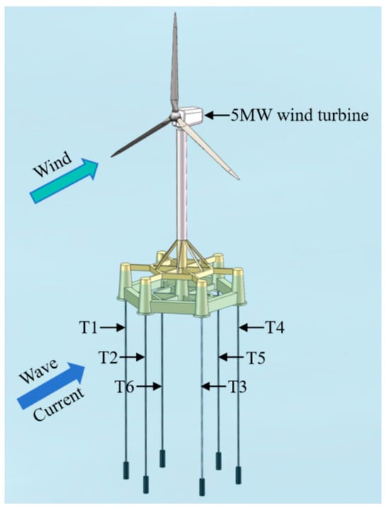
Figure 2.
Schematic layout of the TLP numerical model.

Table 1.
Structural parameters of TLP.
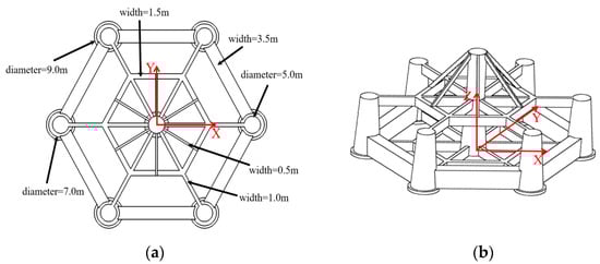
Figure 3.
(a) Plan view; (b) side view of the TLP.
2.2. Wind Turbine Model
The numerical wind turbine model in this study is based on the NREL offshore 5 MW reference turbine. Model design parameters are adopted from the NREL report [28], and the key parameters are listed in Table 2.
Table 2.
Technical specification parameters of a 5 MW wind turbine.
2.3. The Mooring System
The platform’s station-keeping is ensured by a six-tendon mooring system, a configuration chosen to provide a more uniform load distribution and enhanced redundancy. The key performance parameters for this system are based on [29] and are summarized in Table 3. During installation, each tendon’s upper end is secured at the heave-plate center and its lower end anchored to the seabed. In a 100 m water depth deployment, each tendon enhances the system’s vertical stiffness, shortens the heave-mode natural period, and decouples the platform’s heave response from dominant wave frequencies, thereby mitigating resonance risks.
Table 3.
Mooring system properties.
Starting from the tendon aligned with the 0° incident-wave direction in Figure 2 and numbering anticlockwise, the coordinates of the tendon attachment points are given in Table 4.
Table 4.
Coordinates of the upper and lower attachment points of the tendons.
3. Methods
The dynamic response of a TLP under wave-wind-current coupling is a complex nonlinear coupled dynamics problem. To analyze this behavior, this study employs ANSYS-AQWA [30], a commercial software package specializing in the time-domain simulation of the dynamic response and mooring of offshore structures. It was chosen for its extensively validated capabilities in modeling complex hydrodynamics and multi-component tendon systems. The simulation uses a hybrid time-domain/frequency-domain approach, which offers an optimal balance of computational efficiency and accuracy by leveraging both potential-flow theory and time-domain analysis to capture nonlinear effects.
3.1. Hydrodynamic Loads
The floating wind turbine tension-leg platform is a large-scale structure. Under the assumptions of incompressible, inviscid, and irrotational flow, hydrodynamic loads are computed by solving the velocity potential via potential-flow theory [31]:
where is the normal velocity on the body surface, n is the unit normal vector, g is the gravitational acceleration, and d is the water depth. Under the foregoing boundary conditions, the total velocity potential is decomposed into its incident, radiation, and diffraction components as:
where is the incident potential, is the radiation potential, and is the diffraction potential.
The wave excitation force on the structure and the added mass and radiation damping forces induced by the body’s motion can be determined separately. The wave excitation force is obtained by integrating the dynamic pressure over the floating body’s wetted surface:
where n is the outward, S0 is the wetted surface.
3.2. Mooring Systems Restoring Loads
The tension leg serves as the core vertical-stabilizing element of a TLP, remaining in constant tension and thus providing pronounced restraint against heave and pitch motions. In ANSYS-AQWA, tendons are represented by their nonlinear static stiffness and damping characteristics, modeled in the time domain as equivalent springs and dashpots to capture both restoring forces and energy dissipation. Platform displacements induce tendon axial deformations under coupling, and the mechanical response can be expressed in simplified form as:
where k is the equivalent stiffness, is the tendon elongation, c is the damping coefficient, and is the elongation rate.
3.3. Aerodynamic Loads
The aerodynamic loads, comprising lift and drag forces, are computed using blade element momentum theory (BEM) [32]. This model divides the blade radially into 2D airfoil elements, determining forces based on local velocity and angle of attack while neglecting radial and three-dimensional effects. While this BEM model, which relies on 2D airfoil data and assumes rigid blades, cannot capture complex aeroelastic effects, its fidelity is sufficient for this study’s core scope of validating overall platform survivability and stability. The resulting BEM-derived aerodynamic forces are then applied back to the platform, ensuring a physically consistent interaction between the environmental loads and the structure’s dynamic response. Figure 4 illustrates the schematic configuration of a blade element and its corresponding annular ring.
where and are the lift and drag force; is the air density; c is the chord of airfoil; α is the angle of attack; and U1 is the relative speed.
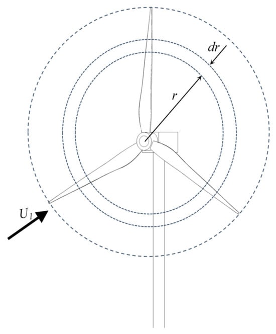
Figure 4.
Schematic layout of the TLP wind turbine.
And the thrust (dT) and the torque () produced by the blade can be described as:
where CL and CD denote the sectional lift and drag coefficients, c represents the local chord length, and K is the total number of blades, r is the distance between airfoil section and blade root, θ is the inflow angle. Then, the aerodynamic loads can be obtained by integrating radially.
Tip losses arise from the vortices generated near the blade tips, which reduce the effective wind speed and thus degrade the blade’s aerodynamic performance. Prandtl’s tip-loss factor is commonly used to correct for this effect and is given by:
where is the tip-loss factor, and R is the rotor radius.
Hub losses arise from flow interference and blockage effects in the vicinity of the hub, which likewise reduce the effective wind speed. The hub-loss correction can be applied in an analogous manner, with the correction factor given by:
is the hub-loss factor, and is the hub radius.
In BEM theory, tip-loss and hub-loss corrections are typically applied by multiplying the respective loss factors:
where and are the lift and drag forces, respectively, corrected for tip-loss and hub-loss effects.
3.4. Equation of Motion
The TLP exhibits very high vertical stiffness, with its heave, pitch, and roll modal frequencies markedly exceeding those of conventionally catenary-moored semi-submersible platforms. As a result, a TLP typically operates in the high-frequency band relative to the dominant wave spectrum, rendering it prone to resonance amplification, particularly under second-order difference-frequency loading, which can induce low-frequency “slow-drift” and coupled instability phenomena. The TLP’s dynamic response is driven not only by environmental excitations (wind, waves, currents) but also by the combined effects of its structural inertia, damping, and restoring forces. To accurately capture its six-degree-of-freedom motion characteristics, a rigid-body equation of motion is formulated. In a unified frequency- or time-domain representation, this takes the form:
where is the six-degree-of-freedom displacement vector; is the body’s mass matrix; is the frequency-dependent added-mass matrix; is the radiation-damping matrix; is the restoring-stiffness matrix; is the wave excitation force; is the mooring system reaction force; is the aerodynamic force, and comprises other environmental loads.
In the above equation, the added-mass matrix and the radiation-damping matrix are derived from frequency-domain potential-flow solutions, reflecting the fluid’s unsteady hydrodynamic response to structural motion. In frequency-domain analysis, the system response is obtained by multiplying the Response Amplitude Operator (RAO) by the environmental load spectrum. In time-domain analysis, the radiation-damping term is incorporated via convolution integrals to capture its temporally lagged memory effects.
3.5. Numerical Model and Validation
The hydrodynamic analysis is performed using ANSYS-AQWA. The methodology for calculating wave loads is selected based on the ratio of the characteristic structural dimension (D) to the wavelength (λ). When D/λ > 0.2, diffraction effects are dominant, making diffraction theory suitable for large-scale structures. Conversely, for small-scale structures where D/λ ≤ 0.2, viscous effects cannot be neglected, and Morison’s equation is employed [33]. Accordingly, a hybrid modeling approach is adopted in this study. Large-scale components, such as the main platform body, are modeled with panels to apply diffraction theory, whereas small-scale members, including connecting rods and heave plates, are defined as Morison elements. The interaction between the submerged structure and the surrounding fluid is a critical determinant of a floating platform’s stability and performance, and thus the wetted surface must be meshed with high resolution. In this study, a wet-surface model is used to decouple the underwater domain from the above-water air region. The maximum panel size for the main body is set to 1.0 m, refined to 0.8 m in the waterline region, while the characteristic size for Morison elements is 0.5 m. The final model consists of 18,071 total panels, with about 17,000 diffraction panels and 300 Morison elements.
In ANSYS-AQWA, mesh validation follows both near-field and far-field methodologies [34]. The near-field approach computes the second-order steady drift force via direct integration of the pressure time series over the mesh, a process highly sensitive to local element quality. In contrast, the far-field method derives the same force from a control volume balance of fluid momentum, offering robustness to coarser meshes and reduced computational cost. As shown in Figure 5, both techniques converge to essentially identical steady drift force predictions, thereby verifying that the current mesh resolution meets the engineering accuracy requirements for deep-water floating wind applications.
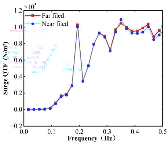
Figure 5.
Second order steady drift force of the TLP.
4. Results and Discussion
This section presents the hydrodynamic performance and structural response of the floating platform. The primary objective of this analysis is to validate the numerical model and comprehensively evaluate the platform’s behavior under specific environmental conditions. To achieve this, the analysis is structured as follows: first, the operating conditions for the simulation are established. Second, a free decay test is performed to determine the system’s natural periods. Subsequently, the platform’s Response Amplitude Operators (RAOs) are calculated to characterize its frequency-domain response. Finally, based on these foundational results, a detailed analysis of the platform’s motion response and the corresponding tendon tensions is conducted to assess its stability and operational safety.
4.1. Operating Conditions Setup
Guided by the DNV-RP-C205 [35], while the standard recommends a 3-h period for a stationary wave analysis, our preliminary results demonstrated that key platform responses achieved statistical convergence well within 1 h. This duration also aligns with the recommended averaging time for wind conditions. Consequently, 3600 s was chosen as a robust and computationally efficient duration for the analysis. The TLP FOWT is designed for a 100 m water depth in accordance with the CCS-Guideline for Certification of Offshore Wind Turbines (2021) [36]. These simulations are based on six representative metocean load cases (LC1-LC6) calibrated for the South China Sea. Both the selection of these load cases and the assumption of collinear (0°) wind, wave, and current forcing are derived from [37]. The environmental loads for these scenarios were modeled as follows: The wind field is generated from the Norwegian Petroleum Directorate (NPD) spectrum with a mean hub-height wind speed of 11.4 m/s, corresponding to the rated speed of the NREL 5-MW reference turbine. Irregular long-crested waves are modeled using the JONSWAP spectrum with a peak enhancement factor γ = 3.3, and are superimposed with a steady, uniform current. The key parameters defining each of the six distinct load cases, such as significant wave height (), peak period (), and current velocity (), are summarized in Table 5.
Table 5.
Load conditions for TLP.
4.2. Free Decay Test
The free decay test is a fundamental procedure for evaluating the motion response and stability of offshore structures, providing a rigorous validation of structural integrity under quiescent sea states. In ANSYS-AQWA, the TLP’s natural periods are obtained by disabling wind and wave forcing and applying small prescribed displacements to the platform. As depicted in Figure 6, the TLP is released from initial offsets of 0.25 m heave, 0.4° pitch, and 10 m surge, and the ensuing time-domain motions are recorded to extract each mode’s natural period. Aerodynamic damping is neglected in this analysis, so restoring forces derive exclusively from hydrodynamic inertia and the tendon mooring system, with all degrees of freedom left unconstrained.
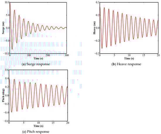
Figure 6.
The dynamic response of the free-decay motion of the TLP model.
The natural periods predicted by our TLP numerical model are compared in Table 6 to data from reference platforms [38,39] and the DNV standard [40]. This comparison reveals that the innovative platform in the present study, owing to its superior inherent stability, exhibits a shorter pitch natural period than DeepCwind. However, the FSP shows the shortest pitch natural period, which is attributed to the high restoring stiffness provided by its hybrid catenary and taut mooring system. Furthermore, since both the present study and DeepCwind utilize six vertically connected tendons, their natural periods in surge and heave are both shorter than those of the FSP. The natural periods of all three platforms are in general agreement with the DNV standard for initial design, which primarily validates the overall mass and stiffness properties of the proposed numerical model. This validation establishes a solid foundation for the subsequent dynamic response simulations.
Table 6.
Natural periods of the TLP.
4.3. Raos Calculation
RAOs are a standard metric for characterizing the dynamic behavior of floating offshore wind turbine. An RAO for a given motion mode is defined as the frequency-dependent ratio of the motion amplitude to a unit-amplitude wave excitation. In this study, time-series records of platform motions and incident wave elevations are transformed into frequency spectra using the Fast Fourier Transform (FFT) function to calculate the RAOs.
The frequency-domain RAOs for surge, heave, and pitch are presented in Figure 7. As depicted, the surge RAO exhibits a decreasing trend with increasing wave frequency, whereas the heave and pitch RAOs display a distinct resonant behavior. The heave RAO reaches its peak at a wave frequency of approximately 0.056 Hz, while the pitch RAO peaks at around 0.059 Hz. The results indicate that the platform’s overall response is dominated by surge motion. The relatively small responses in heave and pitch suggest good platform stability in these degrees of freedom. Furthermore, a strong coupling between the surge and pitch motions is evident from the results. As linear potential-flow results, these RAOs cannot capture non-linearities. Moreover, they neglect viscous damping, which would significantly ‘flatten’ the resonant peaks in Figure 7 and govern the true amplitude. Thus, while RAOs confirm conceptual stability, a non-linear time-domain analysis is essential for assessing survival performance and accurately quantifying fatigue.
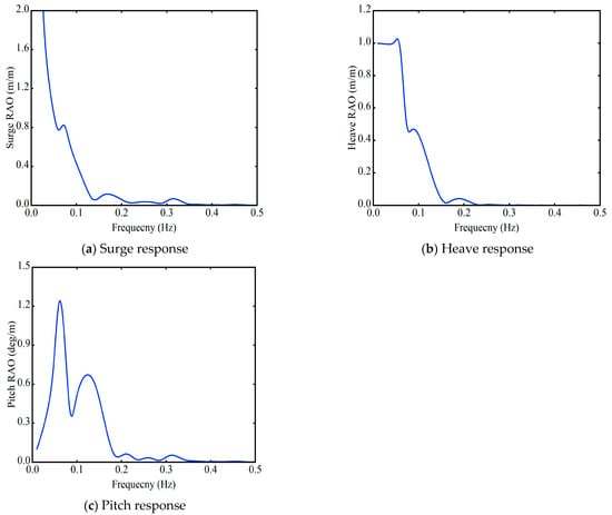
Figure 7.
RAOs of TLP platform in surge, heave, pitch.
4.4. Motion Response Analysis
Figure 8 presents the time-series of wave elevation, surge, and heave responses for the TLP under load cases LC1–LC4 over the time interval between 2000 s and 3000 s displayed for clarity. The data indicate that LC4 produces the largest surge and heave amplitudes, reflecting its more severe metocean conditions compared to LC1–LC3. In contrast, pitch responses remain comparable across all cases, demonstrating the platform’s intrinsic self-stability and the stabilizing effect of evenly distributed tendon array. Moreover, the TLP’s high vertical stiffness yields substantially smaller heave motions relative to surge, underscoring its advantage in mitigating vertical excursions. The following conclusions can be drawn from Figure 8a–c:
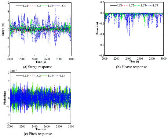
Figure 8.
The time-series wave elevation at LC1–LC4.
For surge motion (Figure 8a), the results reveal its response’s strong sensitivity to the applied load case. Under benign conditions (LC1), the motion is negligible (within ±1.3 m). However, as the sea state severity increases, the response is substantially amplified, with peak excursions reaching 4.7 m in LC3 and a maximum of 9.6 m in LC4. Therefore, the mooring lines and station-keeping ability of the platform must be designed to withstand the extreme offsets observed in this severe environmental state to ensure the overall safety and integrity of the structure.
Figure 8b shows that the heave motion is strongly suppressed and predominantly negative, a key characteristic of the TLP “set-down” effect, where the displacement reaches a maximum of −0.45 m in LC4. This phenomenon is caused by a downward restoring force component from the taut tendons when the platform is pushed into a horizontal offset by wave drift forces. This direct coupling explains why the magnitude of the set-down correlates with the increasing severity of the sea state from LC1 to LC4.
For pitch motion (Figure 8c), the most critical finding is the exceptionally small magnitude of the pitch motion across all conditions, a direct result of the platform’s highly stable design. This is a direct result of the platform’s highly stable design, where the maximum pitch angle is only approximately ±0.2 degrees, even in the most severe sea state (LC4). The motion is characterized by high-frequency oscillations around a zero-mean angle, consistent with a direct response to wave excitation. These results powerfully validate the superior rotational stability of the proposed hexagonal TLP design.
To capture the fully coupled wind–wave–current dynamics, two additional combined load cases (LC5 and LC6) were defined by superimposing uniform current loading and rated-wind-speed aerodynamic forcing onto the baseline JONSWAP wave excitation. Figure 9 presents the significant wave height time series and associated power spectra densities (PSD) for LC5 and LC6. The platform’s dynamic responses in surge, heave, and pitch, presented in both the time domain and through their corresponding PSD plots, are respectively shown in Figure 10, Figure 11 and Figure 12. The spectral analysis clearly indicates that for all three degrees of freedom, the response energy is dominated by a pronounced peak at the primary wave frequency (approximately 0.09 Hz). This confirms that the platform’s behavior is primarily governed by first-order wave-frequency (WF) excitations.
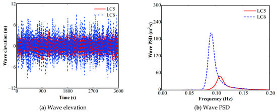
Figure 9.
Time series wave elevation and PSD at LC5 and LC6.
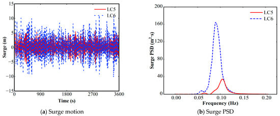
Figure 10.
Time series platform surge and PSD at LC5 and LC6.
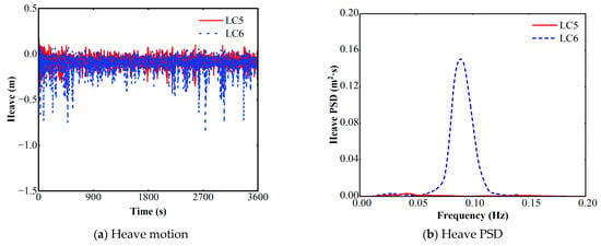
Figure 11.
Time series platform heave and PSD at LC5 and LC6.
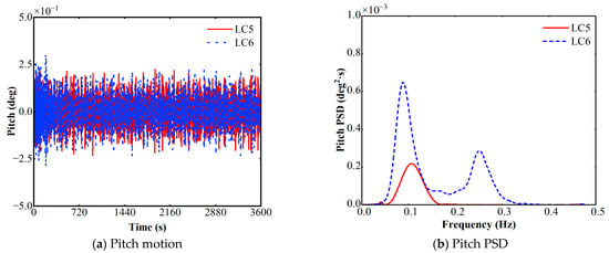
Figure 12.
Time series platform pitch and PSD at LC5 and LC6.
Notably, the pitch spectrum (Figure 12) reveals a distinct secondary energy peak at a higher frequency of approximately 0.25 Hz. This frequency aligns with the platform’s natural pitch frequency, indicating a high-frequency resonant response, often termed the springing effect. This phenomenon is not directly driven by first-order wave forces but is instead excited by second-order sum-frequency wave loads activating the structure’s natural mode. The strong hydrodynamic coupling between the heave and pitch motions further contributes to the amplification of this response. The RAOs analysis in Section 4.3 was unable to predict the response peak observed around 0.25 Hz, as RAOs are fundamentally linear and cannot capture phenomena arising from second-order wave loads. Consequently, the appearance of this springing peak is more than just an important physical characteristic of the platform, and it serves as a strong methodological validation for the necessity of using non-linear time-domain models to evaluate structures of this type.
To further elucidate the platform’s time-localized response characteristics, we performed continuous wavelet transform (CWT) analysis on the heave time series, a localized time-frequency method capable of resolving short-duration, high-energy oscillatory components. Figure 13 presents the CWT of the TLP’s heave response over the 3600-s simulation, providing a time-frequency localization of the signal’s energy. The resulting scalogram is dominated by a persistent, high-energy band centered in the primary WF range of approximately 0.05–0.12 Hz. This band represents the platform’s continuous first-order response to the incident wave field. Superimposed upon this WF response are several intermittent, localized energy bursts, most notably around t = 600 s and t = 2600 s. These events, which coincide with the passage of energetic wave groups, reveal the transient nature of the heave dynamics. They reflect moments of intensified, nonlinear wave-structure interaction and the excitation of higher-order harmonic content that are averaged out in a conventional spectral analysis. In contrast, calmer periods, such as the interval between 1000 s and 1500 s, are characterized by a significantly lower overall spectral intensity, demonstrating the rapid decay of heave oscillations as extreme forcing subsides.
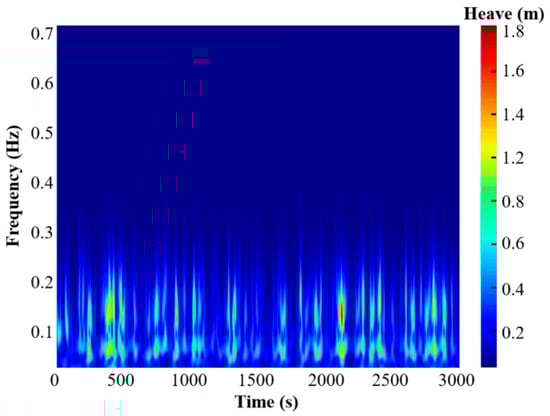
Figure 13.
Wavelet transformation of platform heave at LC6.
The CWT analysis critically reveals the non-stationary nature of the heave response, which has direct and significant implications for the fatigue sizing of critical structural components. Traditional frequency-domain methods, which assume stationarity, would smear the energy of the transient, high-amplitude events observed (around T = 2600 s) across the entire time series. This leads to an underestimation of peak stress amplitudes. Given that fatigue damage is highly non-linear with respect to stress, these infrequent but intense events can contribute a disproportionately large fraction of the cumulative fatigue damage. Therefore, failing to account for them, as a purely descriptive analysis might, could result in a non-conservative fatigue design. Our analysis highlights that a time-frequency approach like the CWT is essential for identifying these critical events, paving the way for a more accurate and reliable fatigue life prediction.
4.5. Tendon Tension Analysis
The structural integrity of the mooring system is critical to the survivability of a floating wind turbine, necessitating continuous monitoring of tendon tensions during severe sea conditions. Table 7 summarizes the maximum, mean, and standard deviation (STD) of tensions in tendons T1–T6 under extreme environmental load cases; symmetry of the platform yields nearly identical tension profiles for T2–T6 and T3–T5 pairs. Furthermore, the platform is designed in accordance with DNVGL-ST-0119 [40] and DNVGL-RP-0286 [41], primarily adhering to the following criteria: the maximum tension shall not exceed the Minimum Breaking Load (MBL) of the tendons, while maintaining a specified factor of safety; and the tendons must not go slack under Ultimate Limit State (ULS) and Accidental Limit State (ALS) conditions.
Table 7.
Statistics of the tendon tension of TLP.
Figure 14, Figure 15, and Figure 16 respectively present the tension time histories for tendons T1, T2, and T6 under the LC5 and LC6 return period load cases, with the initial 600 s of transient response removed from the analysis. A comparative analysis among the tendons reveals that T1, as the primary upwind tendon, consistently experiences the highest mean tension and the largest dynamic oscillation amplitudes. This highlights T1′s governing role in counteracting the combined environmental forces.
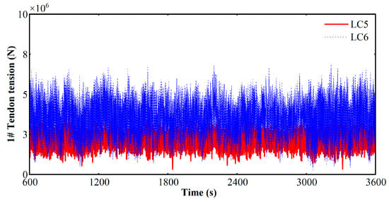
Figure 14.
T1 tension time series.
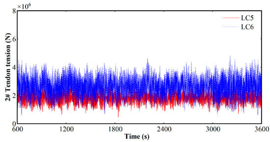
Figure 15.
T2 tension time series.
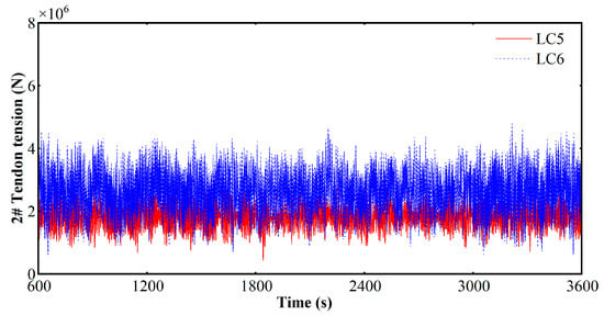
Figure 16.
T6 tension time series.
Furthermore, a comparison between the two load cases demonstrates the more significant impact of the extreme condition; mean and peak tensions across all tendons are substantially higher under LC6 than under the LC5 scenario. Critically, despite the increased loading in LC6, the observed maximum tension remains well below the tendon’s Minimum Breaking Load (MBL) of 37.137 MN. The platform’s exceptional vertical stability, proven by minimal pitch and heave (Section 4.4), even in extreme conditions, prevents catastrophic “snapping” tensions. This high safety margin validates the innovative hydrodynamic design, confirming its avoidance of the TLP’s primary motion-mooring coupled failure mode.
5. Conclusions
This study presents the structural optimization of a six-leg TLP tailored for deep-water conditions and delivers a comprehensive analysis of its nonlinear dynamic response under fully coupled wind–wave–current loading. Leveraging both frequency-domain and time-domain simulations in ANSYS-AQWA, we extract the RAOs and freedom motion time histories for a suite of representative metocean scenarios. The mooring-system tendons are also scrutinized to quantify the tension profiles and differentiate the load-sharing behavior of windward, leeward, and transverse tendons. The optimized TLP confines heave and pitch excursions to within prescribed design thresholds even in extreme sea states, while peak tendon tensions remain safely below the minimum breaking loads, thereby validating the platform’s hydrodynamic performance and structural margins. These results furnish critical insights and practical guidance for the efficient design and reliable deployment of deep-water floating wind turbine platforms. Based on the comprehensive analysis of the novel TLP, the following key conclusions can be drawn:
- (1)
- The innovative truss-type architecture of the TLP enhances both safety and ease of fabrication. Its hexagonal configuration significantly improves self-stability, which is particularly advantageous during transport and installation operations. Furthermore, this design effectively mitigates stress concentrations and improves the platform’s overall hydrodynamic performance.
- (2)
- The frequency-domain analysis reveals the platform’s excellent hydrodynamic response characteristics. Moreover, free-decay simulations show that the natural periods in surge (25.72 s), heave (1.47 s), and pitch (2.17 s) are well outside the typical wave-frequency range, in full compliance with DNV design codes.
- (3)
- Time-domain analysis confirms the platform’s robust stability under extreme sea states. In the most severe load case (LC6), maximum motion amplitudes were recorded as 11.19 m (surge), 0.86 m (heave), and 0.28 degrees (pitch), demonstrating excellent station-keeping and rotational stability. This superior stability was further investigated using the CWT, which proved essential for capturing the non-stationary dynamics and transient peak loads that are critical for reliable fatigue sizing.
- (4)
- The analysis of the mooring system shows that the maximum tension in the most loaded tendon reached 6.82 MN. This corresponds to less than 22% of the tendon’s MBL, providing the first quantitative confirmation of the engineering feasibility and safety of deploying this innovative FOWT design in extreme sea conditions like the South China Sea.
To advance this TLP concept toward commercial deployment, subsequent research will focus on two primary objectives. First, simulation fidelity will be improved by employing a fully coupled hydro-aero-servo-mooring analysis, which incorporates the turbine’s control system to achieve a more holistic performance prediction. Second, a comprehensive physical model testing campaign in a wave tank will be conducted to provide essential experimental validation for these numerical findings, thereby confirming the design’s robustness for commercialization. Third, a rigorous quantitative Fatigue Limit State (FLS) assessment, which was beyond the current scope, remains the critical next step to determine the platform’s long-term operational lifespan.
Author Contributions
Conceptualization, R.Z. and Z.L.; data curation, Z.L. and H.Y.; formal analysis, H.Y.; funding acquisition, R.Z. and H.Q.; investigation, C.L. and K.S.; methodology, R.Z., Z.L. and H.Y.; project administration, Y.X.; resources, Y.X. and K.S.; software, R.Z. and Z.L.; supervision, C.L. and H.Q.; validation, R.Z., C.L. and H.Q.; visualization, Z.L. and Y.X.; writing—original draft, R.Z. and Z.L.; writing—review and editing, C.L. and H.Q. All authors have read and agreed to the published version of the manuscript.
Funding
The offshore wind power research project of CNNP (Grant No. CREC-SR-2024-002).
Data Availability Statement
The original contributions presented in this study are included in the article. Further inquiries can be directed to the corresponding author.
Conflicts of Interest
Authors Chunlong Li, Yingchun Xie and Ke Sun were employed by the company CNNP Rich Energy Co., Ltd. Author Haiping Qian was employed by the company CEEG Zhejiang Electric Power Design Institute Co., Ltd. The remaining authors declare that the research was conducted in the absence of any commercial or financial relationships that could be construed as a potential conflict of interest.
References
- Martynowicz, P.; Ślimak, P.; Katsaounis, G.M. TLP-Supported NREL 5MW Floating Offshore Wind Turbine Tower Vibration Reduction Under Aligned and Misaligned Wind-Wave Excitations. Energies 2025, 18, 2092. [Google Scholar] [CrossRef]
- Tian, Z.; Shi, W.; Li, X.; Park, Y.; Jiang, Z.; Wu, J. Numerical Simulations of Floating Offshore Wind Turbines with Shared Mooring under Current-Only Conditions. Renew. Energy 2025, 238, 121918. [Google Scholar] [CrossRef]
- Shen, M.; Hu, Z.; Liu, G. Dynamic Response and Viscous Effect Analysis of a TLP-Type Floating Wind Turbine Using a Coupled Aero-Hydro-Mooring Dynamic Code. Renew. Energy 2016, 99, 800–812. [Google Scholar] [CrossRef]
- Edwards, E.C.; Holcombe, A.; Brown, S.; Ransley, E.; Hann, M.; Greaves, D. Evolution of Floating Offshore Wind Platforms: A Review of at-Sea Devices. Renew. Sustain. Energy Rev. 2023, 183, 113416. [Google Scholar] [CrossRef]
- Provence Grand Large|Prysmian. Available online: https://www.prysmian.com/en/insight/projects/provence-grand-large (accessed on 8 August 2025).
- Home, DeepCWind. Available online: https://www.deepcwindco.com/ (accessed on 7 August 2025).
- Home. Available online: https://www.bluewater.com/ (accessed on 7 August 2025).
- MODEC. Available online: https://www.modec.com/ (accessed on 7 August 2025).
- PelaStar|The Premier Platform for Floating Offshore Wind. Available online: https://pelastar.com/ (accessed on 7 August 2025).
- GICON-Gruppe|Ingenieurdienstleister—www.gicon.de/DE. Available online: https://www.gicon.de/ (accessed on 7 August 2025).
- Jia, Z.; Wu, H.; Chen, H.; Li, W.; Li, X.; Lian, J.; He, S.; Zhang, X.; Zhao, Q. Hydrodynamic Response and Tension Leg Failure Performance Analysis of Floating Offshore Wind Turbine with Inclined Tension Legs. Energies 2022, 15, 8584. [Google Scholar] [CrossRef]
- Jiang, Z. Mooring Design for Floating Wind Turbines: A Review. Renew. Sustain. Energy Rev. 2025, 212, 115231. [Google Scholar] [CrossRef]
- Ma, Z.; Wang, S.; Wang, Y.; Ren, N.; Zhai, G. Experimental and Numerical Study on the Multi-Body Coupling Dynamic Response of a Novel Serbuoys-TLP Wind Turbine. Ocean. Eng. 2019, 192, 106570. [Google Scholar] [CrossRef]
- Jonkman, J.; Prowell, I.; Robertson, A.; Goupee, A.J.; Stewart, G.M. Numerical Prediction of Experimentally Observed Behavior of a Scale-Model of an Offshore Wind Turbine Supported by a Tension-Leg Platform. In Proceedings of the 2013 Offshore Technology Conference, Houston, TX, USA, 6–9 May 2013; p. OTC-24233-MS. [Google Scholar]
- Vita, L.; Ramachandran, G.K.V.; Krieger, A.; Kvittem, M.I.; Merino, D.; Cross-Whiter, J.; Ackers, B.B. Comparison of Numerical Models and Verification Against Experimental Data, Using Pelastar TLP Concept. In Proceedings of the OMAE2015, Volume 9: Ocean Renewable Energy, St. John’s, NL, Canada, 31 May–5 June 2015. [Google Scholar]
- Hmedi, M.; Uzunoglu, E.; Medina-Manuel, A.; Mas-Soler, J.; Vittori, F.; Pires, O.; Azcona, J.; Souto-Iglesias, A.; Guedes Soares, C. Experimental Analysis of CENTEC-TLP Self-Stable Platform with a 10 MW Turbine. J. Mar. Sci. Eng. 2022, 10, 1910. [Google Scholar] [CrossRef]
- Zhao, Y.; She, X.; He, Y.; Yang, J.; Peng, T.; Kou, Y. Experimental Study on New Multi-Column Tension-Leg-Type Floating Wind Turbine. China Ocean. Eng. 2018, 32, 123–131. [Google Scholar] [CrossRef]
- Zhang, Z.; Wang, X.; Zhang, X.; Zhou, C.; Wang, X. Dynamic Responses and Mooring Line Failure Analysis of the Fully Submersible Platform for Floating Wind Turbine under Typhoon. Eng. Struct. 2024, 301, 117334. [Google Scholar] [CrossRef]
- Guillaume, B.; Christian, B.; Christine, B.; Cecile, M.; Timothee, P.; Yann, P. Design and Performance of a TLP Type Floating Support Structure for a 6MW Offshore Wind Turbine. In Proceedings of the Offshore Technology Conference, Houston, TX, USA, 6 May 2019; p. D031S033R005. [Google Scholar]
- Wang, Y.; Yao, T.; Zhao, Y.; Jiang, Z. Review of Tension Leg Platform Floating Wind Turbines: Concepts, Design Methods, and Future Development Trends. Ocean. Eng. 2025, 324, 120587. [Google Scholar] [CrossRef]
- Lefebvre, S.; Collu, M. Preliminary Design of a Floating Support Structure for a 5MW Offshore Wind Turbine. Ocean. Eng. 2012, 40, 15–26. [Google Scholar] [CrossRef]
- Shen, M.; Hu, Z.; Geng, T. Coupled Hydrodynamic and Aerodynamic Response Analysis of a Tension-Leg Platform Floating Wind Turbine. J. Ship Mech. 2017, 21, 263–274. [Google Scholar]
- Nejad, A.R.; Bachynski, E.E.; Kvittem, M.I.; Luan, C.; Gao, Z.; Moan, T. Stochastic Dynamic Load Effect and Fatigue Damage Analysis of Drivetrains in Land-Based and TLP, Spar and Semi-Submersible Floating Wind Turbines. Mar. Struct. 2015, 42, 137–153. [Google Scholar] [CrossRef]
- Xue, Y.; Wang, J.; Zhao, W.; Wan, D. Numerical Analysis of Effects of Wind-Wave-Current Interactions on the Performance of Floating Offshore Wind Turbine. In Proceedings of the 35th International Ocean and Polar Engineering Conference, Seoul, Republic of Korea, 1–6 June 2025. [Google Scholar]
- Wei, D.; Yuan, L.; Ji, X.; Wang, N.; Wang, L.; Liu, X. Dynamic Response and Power Generation of Floating Offshore Wind Farms under Different Wave Conditions Using an Efficient Evaluation Method. Phys. Fluids 2025, 37, 073334. [Google Scholar] [CrossRef]
- Ren, Y.; Shi, W.; Venugopal, V.; Zhang, L.; Li, X. Experimental Study of Tendon Failure Analysis for a TLP Floating Offshore Wind Turbine. Appl. Energy 2024, 358, 122633. [Google Scholar] [CrossRef]
- Rony, J.S.; Karmakar, D. Hydrodynamic Response Analysis of a Hybrid TLP and Heaving-Buoy Wave Energy Converter with PTO Damping. Renew. Energy 2024, 226, 120380. [Google Scholar] [CrossRef]
- Jonkman, J.; Butterfield, S.; Musial, W.; Scott, G. Definition of a 5-MW Reference Wind Turbine for Offshore System Development; NREL/TP-500-38060; NREL: Golden, CO, USA, 2009; p. 947422. [Google Scholar]
- Barros, P.; Lillestøl, D.-B.; Østby, E.; Olsen, J.H.; Yttervik, R. Review of Available Material on Usability and Suitability of High Strength Mooring Chain. In Proceedings of the 33rd International Ocean and Polar Engineering Conference, Ottawa, ON, Canada, 19–23 June 2023. [Google Scholar]
- Ansys Help. Available online: https://ansyshelp.ansys.com/public/account/secured?returnurl=/Views/Secured/main_page.html?lang=en (accessed on 17 October 2025).
- Faltinsen, O. Sea Loads on Ships and Offshore Structures; Cambridge University Press: Cambridge, UK, 1993; ISBN 978-0-521-45870-2. [Google Scholar]
- Moriarty, P.J.; Hansen, A.C. AeroDyn Theory Manual; National Renewable Energy Lab.: Golden, CO, USA, 2004. [Google Scholar]
- Ding, Q.; Li, C.; Yu, N.; Hao, W.; Ji, J. Numerical and Experimental Investigation into the Dynamic Response of a Floating Wind Turbine Spar Array Platform. J. Mech. Sci. Technol. 2018, 32, 1106–1116. [Google Scholar] [CrossRef]
- Yue, M.; Liu, Q.; Li, C.; Ding, Q.; Cheng, S.; Zhu, H. Effects of Heave Plate on Dynamic Response of Floating Wind Turbine Spar Platform under the Coupling Effect of Wind and Wave. Ocean. Eng. 2020, 201, 107103. [Google Scholar] [CrossRef]
- DNV-RP-C205 Environmental Conditions and Environmental Loads. Available online: https://www.dnv.com/energy/standards-guidelines/dnv-rp-c205-environmental-conditions-and-environmental-loads/ (accessed on 11 September 2025).
- CCS. Guideline for Certification of Offshore Wind Turbines. 2021. Available online: https://www.ccs.org.cn/ccswz/articleDetail?id=202110201078111112 (accessed on 11 September 2025).
- Yu, W.; Ding, Q.; Li, C.; Ye, Z. Time-Domain and Mooring Intensity Analysis of Motion Response of Tension Leg Platform of Floating Wind Turbines under Multiple Operating Conditions. J. Eng. Therm. Energy Power 2018, 33, 119–127. [Google Scholar] [CrossRef]
- Ren, Y.; Venugopal, V.; Shi, W. Dynamic Analysis of a Multi-Column TLP Floating Offshore Wind Turbine with Tendon Failure Scenarios. Ocean. Eng. 2022, 245, 110472. [Google Scholar] [CrossRef]
- Wang, X.; Zhang, Z.; Zhuge, P. Transient Analysis of a Novel Full Submersible Floating Offshore Wind Turbine with CFRP Tendons. Ocean. Eng. 2022, 266, 112686. [Google Scholar] [CrossRef]
- DNV GL. DNVGL-ST-0119 Floating Wind Turbine Structures. DNV GL. 2021. Available online: https://www.dnv.com/energy/standards-guidelines/dnv-st-0119-floating-wind-turbine-structures/#:~:text=This%20DNV%20standard%20%28ST%29%20specifies%20general%20principles%20and,the%20structural%20design%20of%20floating%20wind%20turbine%20structures (accessed on 11 September 2025).
- DNV-RP-0286-Coupled Analysis of Floa Ting Wind Turbines. Available online: https://www.dnv.com/energy/standards-guidelines/dnv-rp-0286-coupled-analysis-of-floating-wind-turbines/#:~:text=Get%20a%20preview%20of%20DNV-RP-0286%20here%20%28PDF%29%20This,be%20used%20in%20combination%20with%20the%20referenced%20standards (accessed on 11 September 2025).
Disclaimer/Publisher’s Note: The statements, opinions and data contained in all publications are solely those of the individual author(s) and contributor(s) and not of MDPI and/or the editor(s). MDPI and/or the editor(s) disclaim responsibility for any injury to people or property resulting from any ideas, methods, instructions or products referred to in the content. |
© 2025 by the authors. Licensee MDPI, Basel, Switzerland. This article is an open access article distributed under the terms and conditions of the Creative Commons Attribution (CC BY) license (https://creativecommons.org/licenses/by/4.0/).