Abstract
The design of offshore monopile foundations typically follows an iterative process aimed at optimizing key geometric parameters—namely, pile diameter, wall thickness, and embedded length. Among these, selecting an appropriate embedded length is a critical step in geotechnical design, as it must satisfy both stability and serviceability requirements. The critical pile length is defined as the embedment depth beyond which additional penetration yields no significant improvement in lateral capacity and at which the pile reaches its critical lateral capacity. From a design standpoint, extending the pile beyond this length offers no further gain in resistance, rendering such an approach both inefficient and uneconomical. To evaluate and characterize the critical length of offshore monopile foundations, three-dimensional finite element (3D FE) analyses were performed on laterally loaded monopiles using the NGI-ADP constitutive model. The analyses considered a wide range of pile geometries, load eccentricities, and soil properties. This study first investigate how geotechnical parameters affect lateral response, then characterizes the critical lateral capacity () and critical pile length () based on the analyzed cases. Finally, an empirical equation was developed to estimate the critical embedment depth of monopiles in clay. Results indicate that higher undrained shear strength () or lower ultimate plastic shear strain () considerably reduce the critical pile length, whereas it is increased with greater pile head rotation. The normalized critical length is largely independent of pile diameter and load eccentricity. These insights provide practical guidance for geotechnical design by offering an efficient method to estimate critical pile length, supporting informed decisions on the required embedment depth.
1. Introduction
Offshore wind energy has become a cornerstone of the global transition to renewable energy, offering a sustainable solution for large-scale electricity generation [1]. Benefiting from stronger and more consistent wind conditions over open seas, offshore wind farms achieve higher capacity factors and greater energy yields compared to their onshore counterparts [2]. To harness this potential, turbines are supported by a range of fixed and floating foundation systems. Among these, monopile foundations are the most widely used, particularly in shallow to intermediate water depths of up to 35 m [3].
Traditionally, the design of offshore monopile foundations has relied on the standard p–y method—a simplified one-dimensional (1D) approach that models the pile as an embedded Euler–Bernoulli or Timoshenko beam supported by nonlinear springs representing lateral soil resistance. Each spring defines resistance per unit pile length (p) as a function of lateral deflection (y). This method, as outlined in design guidelines such as API RP 2A-WSD and DNVGL-ST-0126, was originally developed from empirical data on long, slender piles (high L/D ratios, typically around 40), primarily used in offshore oil and gas platforms [4,5]. However, the large-diameter, low L/D ratio monopiles commonly used in offshore wind applications differ significantly in both geometry and loading characteristics [6,7]. This discrepancy has prompted the development of alternative design frameworks, notably the Pile Soil Analysis (PISA) project [7], which integrated full-scale field testing and 3D finite element (FE) modeling tailored to offshore wind conditions.
The design of offshore monopile foundations typically follows an iterative process aimed at optimizing key geometric parameters—namely, pile diameter, wall thickness, and embedded length. Among these, the selection of an appropriate embedded length is a critical step in geotechnical design, as it must satisfy both stability and serviceability requirements. Numerous criteria exist for determining suitable embedment, often leading to significantly different results. In many offshore projects, a rigid grip of the pile within the subsoil under static loading is desirable. This condition is commonly defined by the presence of two zero-deflection points along the pile or at least a vertical tangent in the deflection profile [8,9]. However, for large-diameter monopiles with high bending stiffness, these criteria can lead to excessively long embedment depths [10].
As a more practical alternative, DNVGL (2016) recommends evaluating how increasing the embedded length influences pile head displacement and selecting a length corresponding to the “flat region” of the displacement–length curve—i.e., where further increases in embedment produce negligible changes in pile head deflection [5]. These descriptions closely align with the concept of a critical pile length, defined as the embedment depth beyond which additional penetration yields no significant improvement in lateral resistance. In essence, while lateral capacity increases with embedment, the rate of increase gradually diminishes and eventually plateaus. From a design standpoint, extending the pile beyond this critical length offers no further gain in lateral capacity, rendering such an approach both inefficient and uneconomical.
The concept of the critical pile length for laterally loaded piles can be traced back to the classical beam-on-elastic-foundation model proposed by Hetenyi (1946) [11]. According to this model, once a pile extends beyond a certain threshold length, its lateral response becomes largely insensitive to further embedment. Only the upper portion of the pile contributes significantly to deformation and bending moments, while the deeper portion plays a negligible role.
Several researchers have attempted to define the critical pile length analytically. Using approximate elastic analysis and an integral equation approach, Davies and Banerjee (1978) [12] demonstrated that, for flexible piles, a large portion of the lateral resistance is concentrated in the upper section, confirming the existence of a threshold depth beyond which additional length has little effect. To quantify this, they introduced the relative flexibility factor (), expressed as the ratio of the pile’s flexural rigidity () to the effective stiffness of the surrounding soil (). For flexible piles, values of this factor below 10−4 correspond to the critical length.
Poulos and Davis (1980) [13] proposed an approach based on the subgrade reaction method, while Randolph (1981) [14], using finite element analysis with a linear elastic soil model, derived relationships that explicitly account for the influence of Poisson’s ratio on pile deformation. His findings showed that, within an elastic medium, the lateral pile response is governed more by the soil’s Young’s modulus in the lateral direction than by its shear modulus.
Despite these contributions, existing formulations are fundamentally limited by the assumption of linear elasticity. They require reliable estimates of an equivalent soil modulus and its variation with depth—parameters that are notoriously difficult to determine in practice. Real soils exhibit nonlinear and inelastic behavior, and even when an elastic modulus is assumed, it evolves with the level of deformation. As a result, the direct application of these analytical relationships in design can lead to inaccuracies and reduced reliability.
In a more recent contribution, Hu et al. (2021) investigated the critical length of piles () in sand using three-dimensional finite element analyses [15]. They defined the as the depth at which the pile reaches its critical lateral capacity, , beyond which further embedment does not enhance capacity. Their results—based on varying pile geometries, sand types, and relative densities—showed that can be expressed as a function of pile diameter (its cross-sectional moment of inertia ()) and sand relative density ().
While the work of Hu et al. [15] provides valuable insights, it is confined to sandy soils. The concept of critical pile length, despite its practical significance, remains underdeveloped for piles embedded in clay. To address this gap, the present study explores the critical length of monopiles in clayey soils using three-dimensional finite element (3D FE) analyses. The analyses evaluate lateral pile capacity at specific degrees of rotation across various embedment lengths to determine the critical length. To examine the influence of clay properties and stress–strain behavior, three representative undrained shear strengths (30, 60, and 180 kPa) were considered. Clay profiles were characterized by varying ultimate plastic shear strain () and the ratio of small-strain shear modulus to undrained shear strength (). Various pile geometries—including different diameters, slenderness ratios, and load eccentricities—were also considered, while maintaining a constant diameter-to-thickness ratio (). Collectively, these results were used to identify the key geotechnical and geometric factors affecting critical pile length, upon which an empirical equation was proposed to estimate critical embedment depth for offshore monopiles in clay.
2. Finite Element Modeling
To investigate the behavior of monopiles subjected to lateral loading, a comprehensive numerical study was performed in PLAXIS 3D (V2024.1.0). This software incorporates advanced constitutive models capable of capturing the nonlinear and anisotropic behavior of soils with high fidelity. The simulations were conducted across a range of geometries and geotechnical conditions, as summarized in Table 1. Geometrical variations included length-to-diameter (L/D) ratios ranging from 4 to 20, pile diameters of 2 and 8 m, and load eccentricities of 30 and 80 m. While typical monopile designs employ L/D ratios below 10, a larger ratio of 20 was considered to ensure the load–displacement response reached a fully flattened asymptote, indicating critical lateral load capacity () which will be elaborated upon in the next section. The diameter-to-wall thickness () ratio was held constant at 100 throughout all simulations. Key geotechnical parameters included the undrained shear strength (), the ratio of small-strain shear modulus to undrained shear strength (), and the ultimate plastic shear strain (). The submerged soil unit weight () was kept constant across all models.

Table 1.
Summary of soil parameters, pile geometries, and loading eccentricities analyzed.
2.1. Constitutive Model
In this study, the NGI-ADP elastoplastic constitutive model was used to simulate the undrained behavior of clay soils, as described in references [16,17]. This model employs a total stress approach and is specifically designed to capture anisotropic responses by allowing direct assignment of undrained shear strengths for active (A), passive (P), and direct simple shear (D) loading modes. This capability makes it particularly well-suited for analyzing laterally loaded monopiles in clay, where the soil experiences a variety of stress conditions [18]. These include triaxial compression behind the pile, triaxial extension at shallow depths in front of the pile, direct simple shear around the center of rotation depth, and a combination of these loading modes toward the pile tip (Figure 1). Accurately capturing the soil’s response under such diverse loading paths is essential for realistic modeling. Table 2 summarizes the input parameters required for the NGI-ADP model and their descriptions.
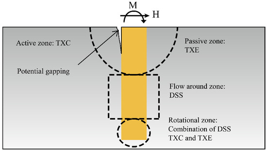
Figure 1.
Stress conditions (paths) adjacent to a monopile under lateral load [19].
Table 2.
NGI-ADP constitutive model parameters.
The drainage condition was defined as “Undrained (C)” to facilitate analysis under total stress conditions using undrained parameters. In modeling monopiles in clay, it is important to account for the gap that forms between the pile and the surrounding soil during loading. In onshore conditions, where this gap is dry, the saturated unit weight of the soil is appropriate. However, in offshore scenarios, water immediately fills the gap around the pile. Therefore, the submerged unit weight should be used, even in total stress analyses, to reflect the counteracting water pressure around the pile [20]. Accordingly, the submerged unit weight was adopted for the soil in this study, with the phreatic level positioned at the base of the model. The submerged unit weight of the clay (γ′) and the coefficient of lateral earth pressure at rest () were set to 9 kN/m3 and 1.0, respectively.
The ratio was calculated using [17]:
where represents the initial vertical effective stress (positive in compression). The relationship between the ultimate plastic strains for compression, extension, and direct shear is defined as follows [21]:
To consider strength anisotropy, the and were set to 0.5 and 0.75, respectively, while is set to 0.99 [21]. The monopile was modeled as a linear elastic material, using typical steel properties with a Young’s modulus of and Poisson’s ratio of .
2.2. Finite Element Mesh, Interfaces, and Boundary Condition
Figure 2 presents the finite element model’s geometry and mesh, along with relevant notations. Owing to symmetry, half of the monopile–soil system was modeled. The monopile is modeled as a steel half-pipe with an open end and a wall thickness denoted by . To minimize boundary influences, the numerical domain is defined with a vertical extent equal to twice the pile embedment depth (2L), and lateral boundaries located six pile diameters (6D) in the loading direction and four pile diameters (4D) perpendicular to it, measured from the pile centerline [21]. Fixed boundary conditions are assigned to the bottom of the model, whereas normally fixed conditions (i.e., the displacement normal to the side boundaries was restrained while tangential movement was allowed) were applied to the lateral boundaries. A 10-node tetrahedral mesh is used for the soil, and 6-node triangular elements are adopted for the structural plate elements.
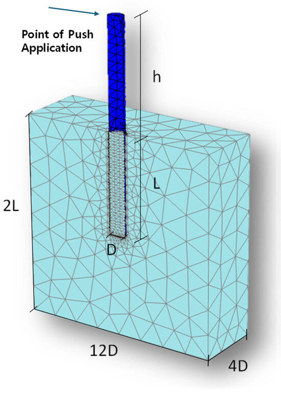
Figure 2.
Geometry and mesh configuration of the 3D finite element model.
To capture potential soil–pile slip or gapping, an interface was implemented between the monopile and the surrounding soil using joint elements. A Mohr–Coulomb model with tension cut-off governed its behavior. The interface stiffness followed the NGI-ADP soil properties, and its undrained shear strength was taken as 65% of the surrounding clay strength.
2.3. Simulation Steps
The initial stress field is generated using the procedure for the soil. A total-stress, undrained approach is adopted, and submerged unit weight is used because the gap around the monopile fills with water in an offshore environment. In Phase 1, monopile and interface elements are activated and the model is brought to equilibrium; resulting movements are reset in the following phase. The “wished-in-place” installation assumption is adopted, as it is considered valid for large-diameter monopiles driven by vibratory hammers in clay, where (i) soil plugging is typically absent [22], and (ii) the lateral resistance mainly derives from mobilizing a large volume of undisturbed soil beyond the zone affected by installation [23]. In Phase 2, horizontal loading is applied under displacement control until a 0.2D mudline displacement is reached, ensuring the full load–displacement behavior is captured. A rigid head plate enforces uniform pile-head movement.
2.4. Verification
The numerical model was validated using data from the CL2 pile test conducted at the Cowden site as part of the PISA project [24]. Among the test series, the CL2 monopile had the largest dimensions, with an outer diameter of 2.0 m, an embedded length of 10.6 m, a loading eccentricity of 10.1 m, and a wall thickness of 25 mm. To simulate actual site conditions, the ground profile was created using site investigation results and the NGI-ADP soil model [25,26]. This profile includes roughly 40 m of over-consolidated clay till overlying a chalk layer, with the groundwater table situated 1 m below the surface. The saturated bulk unit weight () is given as 21.19 kN/m3. Figure 3 illustrates the depth-dependent variation in soil parameters such as the small-strain shear modulus (), undrained shear strength (), effective stress lateral earth pressure coefficient (), and observed pore water pressures (U). A detailed overview of the site conditions can be found in Zdravković et al. (2020) [26].
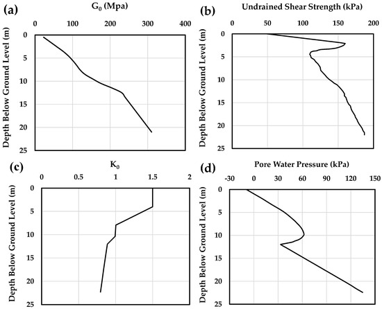
Figure 3.
Initial soil conditions at the Cowden site: (a) small-strain shear modulus (), (b) undrained compressive shear strength (), (c) effective stress lateral earth pressure coefficient (), and (d) pore water pressure (U). Data sourced from [25,26].
Figure 4 presents a comparison between the simulated lateral load–displacement curve and the field measurements reported in [25]. The numerical predictions align well with the observed monopile response, indicating the model’s reliability. Additional information on the modeling approach and its validation is available in [20].
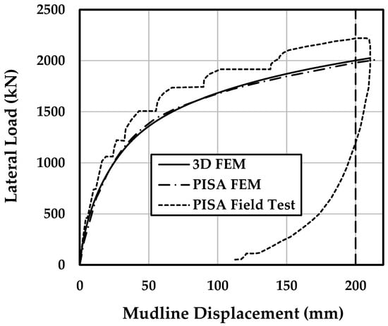
Figure 4.
Comparison of the measured response and 3D FEM prediction for the CL2 test (FEM results and field test data [25,26].
3. Results and Discussions
In this chapter, following a brief introductory discussion on the serviceability and ultimate limit state criteria, Section 3.1 examines the effects of key geotechnical parameters in the NGI-ADP model—namely, the undrained shear strength, ultimate plastic shear strain, and the ratio of small-strain shear modulus to undrained shear strength—on the lateral behavior of monopiles. Section 3.2 then presents a quantitative investigation of the critical pile length for offshore monopile foundations, based on the parameters discussed in Section 3.1, and proposes a new empirical expression for its estimation. The chapter concludes with illustrative examples evaluating the accuracy and applicability of the proposed equation.
According to DNV guidelines, the geotechnical design of laterally loaded piles under combined lateral and moment loading must satisfy both the Ultimate Limit State (ULS) and the Serviceability Limit State (SLS). The ULS assessment ensures stability against geotechnical failure. However, verification based solely on the theoretical lateral capacity of the monopile is often inadequate, as unacceptable pile head displacements may occur well before full mobilization of soil resistance [5]. Consequently, a criterion based on pile head displacement often governs the design. The SLS criterion ensures that pile deformations remain within acceptable limits throughout the service life of the monopile foundation. DNV specifies that the rotation limit should be defined in the project’s design basis, typically provided by the turbine manufacturer. Although a rotation limit of 0.5° is frequently cited in the literature, DNV offers this value only as an example; the actual limit must be determined based on project-specific requirements.
A summary of rotation and deflection values for the SLS and ULS adopted in the literature is provided in Table 3. Since these values are expressed both in terms of monopile rotation or deflection, it is useful for designers to understand their interrelation. Figure 5 presents this relationship for the analyzed cases with various diameters and L/D ratios under different soil conditions ( = 30, 60, and 180 kPa), at load eccentricities of 30 m and 80 m. The mudline deflection is normalized by pile diameter. The average relationships between normalized deflection (v/D) and rotation (θ) for these cases can be expressed using Equation (3).
v/D = 0.013θ2 + 0.031θ
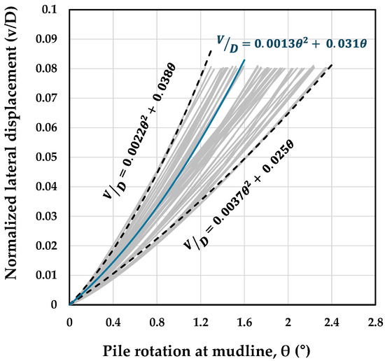
Figure 5.
Relationship between normalized pile deflection (v/D) and pile rotation (θ) at the mudline for cases with varying pile geometries in clay, analyzed across different undrained shear strengths and load eccentricities of 30 m and 80 m.
Based on this relationship, typical mudline rotations of 0.25°, 0.5°, and 2° correspond roughly to deflections of 1%, 2%, and 10% of the monopile diameter, respectively. Considering the various pile head rotation limits adopted in design, the present study applies loading well beyond the commonly used SLS thresholds, extending up to θ = 2°. Lateral pile capacities are specifically evaluated at mudline rotations of θ = 0.5° (widely adopted as the SLS criterion [6,27]) and θ = 1°.
Table 3.
Summary of the ultimate limit state (ULS) and serviceability limit state (SLS) criteria reported in the literature for laterally loaded monopiles.
Table 3.
Summary of the ultimate limit state (ULS) and serviceability limit state (SLS) criteria reported in the literature for laterally loaded monopiles.
| Source | SLS | ULS |
|---|---|---|
| Luo et al. (2018) [28] | ||
| Klinkvort & Hededal (2013) [29] | ||
| Ahmed & Hawlader (2016) [30] | ||
| Zdravković et al. (2015) [31] | ||
| Doherty & Gavin (2012) [6] | ||
| Arany et al. (2017) [27] | or | |
| Khezri et. al. (2024) [20] | (~) | |
| Kaynia (2021) [32] |
3.1. Effect of Clay Properties on the Response
Monopiles subjected to lateral loading experience a combination of bending and rotation, with the relative contribution of each influenced by the pile’s embedment depth and stiffness. Short monopiles with low L/D ratios predominantly rotate about a center of rotation, showing minimal bending—essentially behaving as rigid bodies undergoing rotation and translation. In contrast, longer, more slender piles (higher L/D ratios) exhibit increased bending and reduced rotation.
Figure 6a,b illustrate the lateral load–rotation response of 2 m and 8 m monopiles with ratios of 4 and 10 in homogeneous soil with varying undrained shear strengths (). The results indicate that, for both pile diameters, short piles () exhibit a rapid reduction in stiffness with increasing rotation, whereas long piles () show a more linear and less curved response. This trend suggests that short piles behave more rigidly, as their limited embedment depth reduces the contribution of flexural capacity to restraining pile-head displacement. Consequently, lateral loading results in larger soil displacements near the mudline and an earlier onset of nonlinear soil behavior.
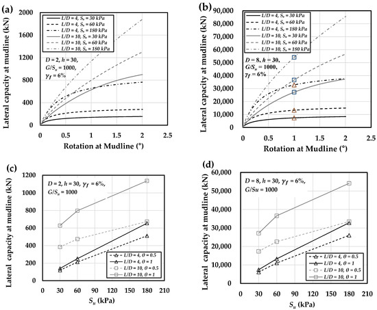
Figure 6.
Load–rotation behavior for monopiles in clay with of 30, 60, and 180 kPa: (a) 2 m and (b) 8 m diameter piles. Panels (c,d) present the corresponding lateral capacities at pile rotations of 0.5° and 1° (at mudline) for the 2 m and 8 m monopiles, respectively (The triangular and square markers at a rotation angle of 1° in (b) illustrate the points from which the lateral capacity values for L/D = 4 and 10 are derived, respectively).
Figure 6c,d compare short versus long monopiles in uniform clay with varying , at rotations of 0.5° and 1°. Increasing enhances lateral capacity for both cases, but the effect is far stronger for short piles. A sixfold increase in (30 → 180 kPa) raises short-pile resistance by roughly 340%, compared to only 87% for long piles. This underscores the stronger reliance of short piles on the soil strength, given their rigid and non-flexural response.
Moreover, the increase in lateral capacity with rising is more pronounced at a rotation of 1° than at 0.5°, suggesting that soil resistance plays a more dominant role at larger deformations. For long piles, the growth in capacity is more pronounced between 30 and 60 kPa but shows a reduced rate of growth beyond that range. In contrast, short piles display a nearly linear increase throughout. This further confirms that short pile capacity is mainly influenced by soil resistance, whereas long pile performance depends on both soil strength and pile bending stiffness.
In addition to undrained shear strength, which plays a critical role in the response of laterally loaded monopiles within the NGI-ADP constitutive model, two other soil parameters—the ultimate plastic shear strain () and the ratio of small-strain shear modulus to the undrained shear strength ()—can influence the stress–strain behavior of clay. These parameters can, in turn, affect the lateral load capacity of monopile foundations, and their effects therefore warrant further investigation.
The NGI-ADP model employs a Tresca-type yield criterion and incorporates a nonlinear hardening law that relates the current yield stress with the current plastic shear strain. Calibration of the hardening parameters is typically performed using stress–strain measurements from project-specific laboratory tests. Therefore, the model is well-suited for evaluating the undrained capacity as well as deformation behavior [33]. The plastic hardening rule in the NGI-ADP model is defined as follows:
Here, κ is the plastic hardening parameter, equivalent to the ratio of the currently mobilized shear strength of the soil to its undrained shear strength () and:
= the current plastic shear strain
= the plastic shear strain at failure (full mobilization)
The total shear strain corresponding to the currently mobilized shear stress τ is composed of both elastic and plastic components, denoted as and , respectively:
Here, represents the ratio of small-strain shear modulus over shear strength and is applied to compute the elastic shear deformation across the entire stress range. The NGI-ADP model, therefore, relies on two parameters— and —to characterize the soil’s stress–strain behavior. Zhang and Anderson [34] showed that, with appropriate selection of the mentioned parameters, this model effectively captures the stress–strain responses of a wide range of natural clays.
To assess the impact of ultimate plastic shear strain on the load–rotation behavior of monopiles, the stress–strain response of the NGI-ADP model under triaxial compression was analyzed using a constant undrained shear strength of = 30 kPa and = 1000, as shown in Figure 7a. The results indicate that the ultimate plastic shear strain () noticeably affects the stress–strain response within the range of 2% to 16%. Beyond = 16%, its effect appears to diminish, as indicated by the relatively small difference between the responses at = 16% and 20%. As increases, the stress–strain response of the soil becomes progressively softer, leading to softer behavior of the p-y curves as well as the load-rotation response of the monopile, as illustrated in Figure 7b,c. Similar trends are observed in the case with = 180 kPa and = 1000 (Figure 8), confirming the consistency of this behavior across different undrained shear strength levels.
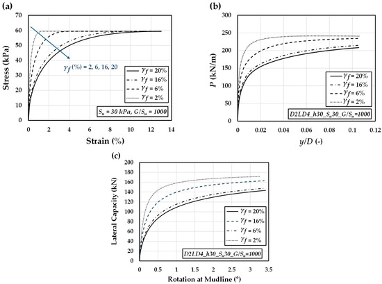
Figure 7.
Effect of ultimate plastic shear strain () on the (a) stress–strain response, (b) p–y behavior, and (c) load–rotation performance of monopile foundations, assuming constant = 30 kPa and = 1000.
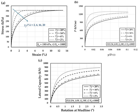
Figure 8.
Effect of ultimate plastic shear strain () on the (a) stress–strain response, (b) p–y behavior, and (c) load–rotation performance of monopile foundations, assuming constant = 180 kPa and = 1000.
The influence of the shear modulus-to-shear strength ratio () on the stress–strain response of the soil model was evaluated for values of 400, 1000, and 1500. The undrained shear strength was kept constant at = 60 kPa, and ultimate plastic shear strains of 2% and 20% were considered. As shown in Figure 9a, the stress–strain curves indicate very limited sensitivity to changes in , with only negligible differences observed across the full range of 400 to 1500 under both plastic strain conditions. A similar trend is seen in the normalized p–y curves (Figure 9b), which show only minor variations as the ratio increases. The same behavior is also reflected in the load–rotation responses (Figure 9c), where lateral capacity remains largely unaffected, with only a small difference between = 400 and the higher ratios at rotations below 1° degree. Figure 10 further supports this observation: increasing the ratio from 400 to 1000 results in a modest 1.1% increase in ultimate lateral capacity, while raising it further to 1500 adds only 0.3%. Overall, the results demonstrate that the ratio has a negligible effect on pile response and can be reasonably disregarded when evaluating the critical pile length.
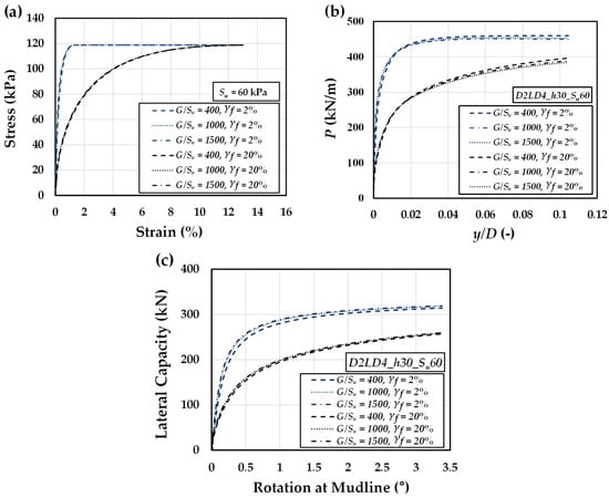
Figure 9.
Effect of the shear modulus-to-shear strength ratio () on the (a) stress–strain response, (b) p-y behavior, and (c) load-rotation performance of a monopile foundation, for ultimate plastic strains of = 2 and 20% in constant = 60 kPa.
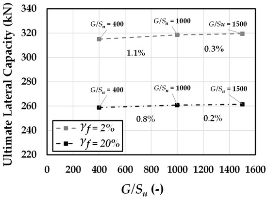
Figure 10.
Ultimate lateral capacity of the representative (D = 2 m, L = 8 m, h = 30 m, = 60 kPa) monopile across varying ratios.
3.2. Critical Pile Length
The lateral capacity of a pile with constant diameter generally increases with greater embedment depth; however, this increase is nonlinear. As the embedment depth grows, the incremental gains in lateral resistance progressively diminish, eventually approaching a threshold beyond which additional length offers negligible improvement. This behavior signifies the presence of a critical embedment length, beyond which further extension does not contribute meaningfully to lateral capacity. Consequently, piles of equal diameter with lengths at or beyond this critical depth will respond similarly under lateral loading [12,14,35].
This phenomenon is illustrated in Figure 11a,b for a 2 m diameter monopile with varying embedment lengths. As can be seen in Figure 11a, increasing the embedment length from 8 m to 20 m results in a substantial gain in capacity, whereas a further increase from 20 m to 40 m produces negligible improvement in lateral resistance. Figure 11b shows the variation in lateral capacity H for piles in clay with representative properties ( = 60 kPa, = 6%, and = 1000), plotted against different slenderness ratios (L/Ds) for pile rotations of θ = 0.5° and θ = 1°. As illustrated, for a fixed pile diameter (in this case, the 2 m monopile), the lateral capacity H increases with pile length until it reaches a critical embedment length , beyond which it levels off at a corresponding critical lateral capacity .
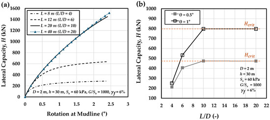
Figure 11.
Influence of pile length (or L/D ratio) on (a) the load–rotation response and (b) the lateral capacity (H) at pile head rotations of θ = 0.5° and 1°, for a 2 m diameter monopile embedded in the representative clay ( = 60 kPa, = 6%, and = 1000) and loaded at 30 m above the mudline.
To investigate how pile length influences lateral pile deflection and to clarify the emergence of a critical lateral capacity , Figure 12 presents the lateral deflection profiles of piles embedded in the representative clay profile (as introduced in Figure 11) under a lateral pile head displacement of 0.1D (0.2 m). For short piles with a low slenderness ratio (L/D = 4), the response is dominated by rigid-body rotation. As the pile length—and consequently the slenderness ratio—increases, the structural response transitions from rigid body rotation to a combination of bending and rotation, indicating increased flexibility. This bending behavior intensifies with further lengthening until a critical length of about L = 20 m is reached. At this point, the pile behaves similarly to a clamped beam, exhibiting negligible toe displacement. For longer piles (e.g., L = 40 m, L/D = 20), the deflection profile in the upper half mirrors that of the 20 m pile, while the bottom half remains effectively undeformed.
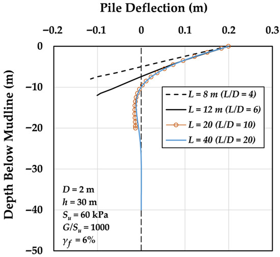
Figure 12.
Effect of L/D ratio on pile head deflection and deflection profiles for a 2 m diameter monopile embedded in representative clay.
Therefore, the segment of the pile beyond the critical embedment depth is essentially an inactive zone, contributing negligibly to lateral resistance and accounting for the plateau observed in the lateral capacity versus slenderness ratio in Figure 11b. From a design standpoint, extending the pile beyond this critical length offers no further gain in lateral capacity, rendering such an approach inefficient and uneconomical.
Figure 13a,b compare soil displacement patterns around the 2 m monopiles with two different embedded lengths: L = 8 m (L/D = 4) and L = 40 m (L/D = 20), respectively. Both piles are installed in the representative clay soil profile and subjected to a lateral displacement of 0.1D at the mudline.
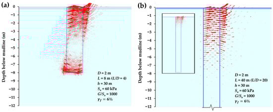
Figure 13.
Vector plots illustrating soil displacement around a 2 m-diameter monopile in the representative soil profile, shown for two cases: (a) L = 8 m (L/D = 4) and (b) L = 40 m (L/D = 20). Displacements are magnified fivefold for visualization.
For the short pile (L/D = 4), the response is dominated by rigid-body rotation, with the surrounding soil mass (both inside and outside the pile) rotating about a center of rotation located at a depth of roughly 5 m (Figure 13a). Behind the pile, this rotation leads to unloading of the clay above the rotation center, while a notable soil displacement is observed below the rotation center. In front of the pile, the clay above the rotation point experiences loading, indicated by the significant soil mass displacement, whereas unloading occurs in the clay below it. Additionally, as the pile toe moves backward, significant shear interaction occurs between the clay plug (the soil mass within the pile) at the base of the monopile and the clay beneath the pile.
In contrast, for the long pile (L/D = 20), the surrounding clay exhibits loading ahead of the pile and unloading behind it in shallow depths (Figure 13b). As the depth increases, the interaction between the soil and pile gradually decreases to a point where there is no soil displacement around the monopile. From Figure 13b, the critical pile length can be roughly identified from the displacement vectors around the monopile. It can be seen that only the upper portion of the monopile length interacts with the surrounding soil, and the total pile length is considerably greater than the critical pile length.
To determine the critical pile length for piles with varying geometries and load eccentricities embedded in clay soils of different geotechnical properties, the lateral capacity ratio () must first be evaluated for different pile lengths. The influence of key geotechnical properties of clay—such as undrained shear strength (), ultimate plastic shear strain (), and the ratio of small-strain shear modulus to undrained shear strength —has already been investigated. Among these, the first two parameters were found to have a significant impact on the lateral response of the pile, while ratio exhibited only a negligible effect.
Figure 14a and Figure 15b present the relationship between the lateral capacity ratio () and the L/D ratio for 2 m and 8 m piles, respectively, embedded in clay with of 30, 60, and 180 kPa. Similarly, Figure 15a,b illustrate the influence of ultimate plastic shear strain on the -L/D relationship for the 2 m pile embedded in clay profiles with undrained shear strengths of 30 kPa and 180 kPa. As evident from both figures, the lateral capacity ratio increases with normalized pile length (L/D) and stabilizes at unity. Based on all FE results corresponding to the cases listed in Table 1, the fitted relationship between and L/D can be expressed as:
where a and n are fitting parameters governing the rate at which the converges to unity. According to Equation (6), increases with normalized pile length (L/D), asymptotically converging to a value of unity. The accuracy of this fitted expression, when compared with FE data, is demonstrated in Figure 14 and Figure 15, confirming its satisfactory predictive capability.
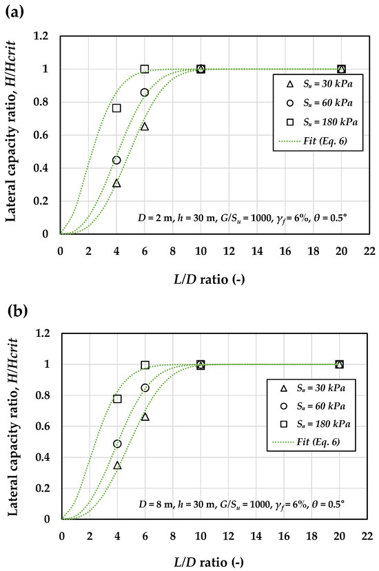
Figure 14.
Effect of undrained shear strength on the relationship between the lateral load capacity ratio () and the L/D ratio for (a) 2 m and (b) 8 m monopile subjected to a load eccentricity of h = 30 m for θ = 0.5° (dotted curves are from Equation (6)).
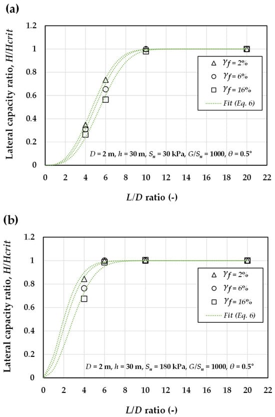
Figure 15.
Effect of ultimate plastic shear strain on the relationship between the lateral load capacity ratio () and the L/D ratio for the 2 m monopile embedded in clay with of (a) 30 kPa and (b) 180 kPa, subjected to a load eccentricity of h = 30 m for θ = 0.5° (dotted curves are from Equation (6)).
Using Equation (6), the normalized critical pile length () was calculated for the analyzed cases. Since the function is asymptotic, the critical pile length is defined as the depth at which the lateral pile capacity reaches 95% of the ultimate capacity, or where the ratio equals 0.95. Table 4 summarizes the computed values for the analyzed cases, which will be used to examine the governing mechanisms, assess the influence of key parameters, and develop an equation for estimating the critical pile length.
Table 4.
Normalized critical pile length ratios () for the analyzed cases, determined using the proposed fit (Equation (6)).
Figure 16 illustrates the variation in normalized critical length () with the undrained shear strength of clay for a pile with a 2 m diameter, evaluated under different levels of ultimate plastic shear strain. As shown in Figure 16a,b, corresponding to a rotation angle of 0.5° and 1°, an increase in undrained shear strength () leads to a reduction in . Moreover, higher levels of ultimate plastic shear strain result in larger values of . This trend is evident in Figure 16a,b, where increasing the plastic strain from 2% to 16% consistently increases across the cases considered.
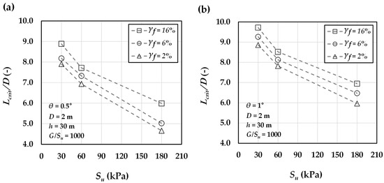
Figure 16.
Variation in normalized critical pile length with undrained shear strength of clay for a 2 m pile, shown at different ultimate plastic shear strains for pile head rotations of (a) θ = 0.5° and (b) θ = 1°.
Both an increase in undrained shear strength and a decrease in ultimate plastic shear strain contribute to a reduction in the critical pile length. This is because, as the surrounding soil becomes stronger and stiffer, the pile can resist the applied lateral load and moment at shallower depths by mobilizing resistance over a shorter length, thereby reaching the critical pile length at a reduced embedment depth. In other words, higher or lower accelerates the convergence of the () ratio toward unity with respect to (L/D), resulting in a smaller normalized critical pile length (). Furthermore, a similar trend is observed in Figure 16a,b for rotation angles of 0.5° and 1°, respectively. However, the results indicate that the critical pile length increases with greater pile head rotation.
The results further demonstrate that the normalized critical pile length () is essentially independent of both pile diameter and load eccentricity. This is illustrated in Figure 17 for a plastic strain of 2% and a rotation angle of 0.5°. As shown, the critical pile lengths of the 2 m and 8 m monopiles differ only marginally, with an average discrepancy of about 2.3%. A similar trend is observed for load eccentricity: the difference between the cases with h = 30 and h = 80 is approximately 1.5%, confirming that neither parameter has a significant influence on .
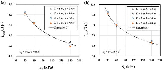
Figure 17.
Variation in normalized critical pile length with undrained shear strength for piles of different diameters and load eccentricities at = 6% and pile head rotation of (a) θ = 0.5° and (b) θ = 1°.
According to the results discussed, the normalized critical pile length () at a given rotation angle is primarily governed by the undrained shear strength and the plastic strain at failure of the clay. Increasing shear strength markedly reduces the critical length, while higher plastic strain and larger rotation angles lead to an increase in . Based on these trends and the values obtained from the analyzed cases, the following expression is proposed to estimate the normalized critical pile length of monopiles:
where the fitting parameters a and C are functions of pile rotation and ultimate plastic shear strain, with their calibrated values given in Table 5, and is the reference atmospheric pressure (). The validity of the proposed equation at an ultimate plastic strain of 6% and rotation angles of 0.5° and 1° is demonstrated in Figure 17a,b, showing good agreement with computed results. The corresponding values for Figure 17a,b are 0.980 and 0.989, respectively.
Table 5.
Calibrated fitting parameters a and c in Equation (7) for various ultimate plastic shear strains and pile head rotations.
Additionally, to examine the accuracy of Equation (7) in predicting the critical pile length, multiple numerical models—independent of those utilized in formula derivation—were developed, as presented in Table 6. The critical pile lengths of these cases were then obtained and compared against the predictions of Equation (7). The FE analyses and Equation (7) predictions showed an average deviation of only 2.8% across the investigated ranges—pile diameters (D) of 2–8 m, load eccentricities (h) of 30–80 m, undrained shear strengths () of 30–180 kPa, ratios of small-strain shear modulus to undrained shear strength () of 400–1500, and ultimate plastic shear strains () of 2–16%—demonstrating good consistency of the proposed formulation despite some parameters exceeding these ranges.
Table 6.
Comparison between the critical pile lengths predicted by the proposed formulation and those obtained from FE simulations for pile mudline rotations of θ = 0.5° and θ = 1°.
4. Conclusions
This study investigated the critical pile length of monopile foundations, defined as the embedment depth beyond which additional penetration provides no significant gain in lateral resistance. The analysis focused on clay soils using the NGI-ADP constitutive model, which captures clay anisotropy and allows direct input of undrained shear characteristics under total stress conditions. The model was validated against large-scale field tests and applied to a range of pile geometries and soil properties. The key findings are:
- Within the NGI-ADP model, two parameters—the clay undrained shear strength and the ultimate plastic shear strain—strongly affect the soil stress–strain response, the p–y behavior of the surrounding clay, and the lateral capacity–rotation response of monopile foundations. In contrast, the influence of the small-strain shear modulus–to–shear strength ratio () within the range of 400–1500 was negligible.
- To determine the critical pile length, the lateral capacity ratio () was calculated for different pile lengths, and a fitting expression relating to normalized pile length (L/D) was established. increases with L/D and asymptotically approaches unity. This behavior was captured using an exponential asymptotic function, which provides a predictive framework for determining the normalized critical pile length, defined as the embedment depth at which lateral capacity reaches 95% of its ultimate value, i.e., where = 0.95. The normalized critical pile lengths derived from the fitted –L/D expression were used to develop a logarithmic regression model for estimating as a function of clay undrained shear strength, ultimate plastic shear strain, and pile head rotation.
- The results demonstrated that an increase in the undrained shear strength or decrease in the ultimate plastic shear strain reduces the critical pile length. This occurs because stronger or stiffer surrounding soil allows the pile to resist applied lateral loads and moments at shallower depths, thereby mobilizing resistance over a shorter embedment and reaching the critical pile length earlier. This accelerates the convergence of toward unity, resulting in smaller values. A similar trend was observed for pile both head rotations of 0.5° and 1°. However, as expected, the results indicate that the critical pile length increases with larger pile head rotations, since greater loads must be resisted.
- The normalized critical pile length () was found to be essentially independent of pile diameter and load eccentricity, with only marginal differences across piles of significantly different geometries.
Future research may focus on integrating the insights from this study on the influence of key design parameters affecting the critical pile length into the design procedures for offshore monopile foundations. This can be achieved by benchmarking and comparing the proposed relationships against existing design criteria—such as the minimum pile-length provisions in DNVGL-ST-0126—and alternative approaches like the vertical tangent and zero-toe-kick methods. Furthermore, the influence of clay anisotropy on the critical pile length warrants a detailed numerical investigation. While previous studies have proposed formulations for sand and the present work introduces one for clay, developing a unified framework capable of predicting the critical pile length in stratified soil profiles containing both sand and clay layers would be highly valuable. Such advancements would extend the applicability of the proposed approach and enhance design reliability across a broad range of offshore foundation conditions.
Author Contributions
Conceptualization, A.K. and D.L.; methodology, A.K. and D.L.; software, A.K.; validation, A.K.; formal analysis, A.K.; investigation, A.K.; resources, D.L.; data curation, A.K. and H.P.; writing—original draft preparation, A.K.; writing—review and editing, A.K. and D.L.; visualization, A.K. and H.P.; supervision, D.L.; project administration, D.L.; funding acquisition, D.L. All authors have read and agreed to the published version of the manuscript.
Funding
This work was supported by the Human Resources Development of the Korea Institute of Energy Technology Evaluation and Planning (KETEP) grant funded by the Korea government Ministry of Trade, Industry & Energy (RS-2021-KP002506) and the Korea Institute of Energy Technology Evaluation and Planning (KETEP) grant funded by the Korea government (MOTIE) (RS-2022-KP002707, Jeonbuk Regional Energy Cluster Training of Human Resources).
Data Availability Statement
The data presented in this study are available upon request from the corresponding author.
Conflicts of Interest
The authors declare no conflicts of interest.
Nomenclature
| pile outer diameter (m) | |
| soil’s submerged unit weight (kN/m3) | |
| coefficient of lateral earth pressure (-) | |
| load application height (m) | |
| embedded length of the pile(m) | |
| critical pile length (m) | |
| length-to-diameter ratio (-) | |
| normalized critical pile length (-) | |
| lateral capacity of pile (kN) | |
| critical lateral capacity (kN) | |
| lateral capacity ratio (-) | |
| thickness of the pile wall (m) | |
| mudline pile rotation (degrees) | |
| Poisson’s ratio of the pile material (-) | |
| pile Young’s modulus (GPa) | |
| undrained shear strength of the clay, also denoted as (kPa) | |
| variation of undrained shear strength with depth (kPa/m) | |
| ratio of small strain shear modulus to (-) | |
| ratio of undrained shear strength in triaxial compression to (-) | |
| ratio of undrained shear strength in triaxial extension to (-) | |
| ratio of undrained shear strength in direct simple shear to (-) | |
| ratio of initial in situ maximum shear stress to (-) | |
| ultimate plastic strain for compression (%) | |
| ultimate plastic strain for extension (%) | |
| ultimate plastic strain for direct shear (%) | |
| current plastic shear strain (%) | |
| initial vertical effective stress (kPa) | |
| undrained shear strength ratio (-) | |
| reference atmospheric pressure (100 kPa) |
References
- Islam, M.R.; Van Nguyen, D.; Park, H.; Lee, D. Nonlinear seismic response and damage mechanism of jacket-supported offshore wind turbines considering soil-structure interaction. Ocean. Eng. 2025, 327, 120953. [Google Scholar] [CrossRef]
- Ali, S.; Waleed, M.; Lee, D. Dynamic Structural Behavior of Monopile Support Structure for 15 MW Offshore Wind Turbine During Different Phases of Operation. J. Mar. Sci. Eng. 2025, 13, 515. [Google Scholar] [CrossRef]
- Islam, M.A.; Ali, S.; Park, H.; Lee, D. Economic Superiority of PIP Slip Joint Compared to Conventional Tubular Joints. Appl. Sci. 2025, 15, 6464. [Google Scholar] [CrossRef]
- RP 2A-WSD; Recommended Practice for Planning, Designing and Constructing Fixed Offshore Platforms. American Petroleum Institute (API): Washington, DC, USA, 2010.
- DNVGL-ST-0126; Support Structure for Wind Turbines. DNV-GL (Det Norske Veritas): Oslo, Norway, 2016.
- Doherty, P.; Gavin, K. Laterally loaded monopile design for offshore wind farms. Proc. Inst. Civ. Eng. Energy 2012, 165, 7–17. [Google Scholar] [CrossRef]
- Byrne, B.W.; McAdam, R.A.; Burd, H.J.; Houlsby, G.T.; Martin, C.M.; Beuckelaers, W.J.A.P.; Zdravković, L.; Taborda, D.M.G.; Potts, D.M.; Jardine, R.J. PISA: New Design Methods for Offshore Wind Turbine Monopiles. In Proceedings of the 8th International Conference on Offshore Site Investigation and Geotechnics, Smarter Solutions for Offshore Developments, London, UK, 12–14 September 2017; Volume 1, pp. 142–161. [Google Scholar]
- Germanischer Lloyd (GL). Guideline for the Certification of Offshore Wind Turbines; GL: Hamburg, Germany, 2005; Volume 49. [Google Scholar]
- Faber, T.; Klose, M. Experiences with Certification of Offshore Wind Farms. In Proceedings of the Sixteenth International Offshore and Polar Engineering Conference, International Society of Offshore and Polar Engineers, Cupertino, CA, USA, 28 May–2 June 2006; pp. 375–382. [Google Scholar]
- Kuo, Y.-S. On the Behavior of Large-Diameter Piles Under Cyclic Lateral Load. Ph.D. Thesis, Institute of Soil Mechanics, Foundation Engineering and Waterpower Engineering, Leibniz University, Hannover, Germany, 2008. [Google Scholar]
- Hetényi, M. Beams on Elastic Foundations; University of Michigan Press: Ann Arbor, MI, USA, 1946. [Google Scholar]
- Davies, T.G.; Banerjee, P.K. The behaviour of axially and laterally loaded single piles embedded in nonhomogeneous soils. Géotechnique 1978, 28, 309–326. [Google Scholar] [CrossRef]
- Poulos, H.G.; Davis, E.H. Pile Foundation Analysis and Design; John Wiley & Sons: Hoboken, NJ, USA, 1980. [Google Scholar]
- Randolph, M.F. The response of flexible piles to lateral loading. Géotechnique 1981, 31, 247–259. [Google Scholar] [CrossRef]
- Hu, Q.; Han, F.; Prezzi, M.; Salgado, R.; Zhao, M. Lateral load response of largediameter monopiles in sand. Géotechnique 2021, 72, 1035–1050. [Google Scholar] [CrossRef]
- Andresen, L.; Jostad, H.P. Application of an Anisotropic Hardening Model for Undrained Response of Saturated Clay. In Numerical Models in Geomechanics; CRC Press: Boca Raton, FL, USA, 2020; pp. 581–585. [Google Scholar]
- Grimstad, G.; Andresen, L.; Jostad, H.P. NGI-ADP: Anisotropic Shear Strength Model for Clay. Int. J. Numer. Anal. Methods Geomech. 2012, 36, 483–497. [Google Scholar] [CrossRef]
- Minga, E.; Burd, H.J. Validation of PLAXIS MoDeTo Based on the Cowden Till PISA Field Tests; Oxford University: Oxford, UK, 2019. [Google Scholar]
- Khezri, A.; Park, H.; Lee, D. Numerical Analysis of Offshore Monopile Foundations in Layered Clay. Appl. Ocean Res. 2025, 161, 104685. [Google Scholar] [CrossRef]
- Khezri, A.; Park, H.; Lee, D. Numerical study on the lateral load response of offshore monopile foundations in clay: Effect of slenderness ratio. Appl. Sci. 2024, 14, 8366. [Google Scholar] [CrossRef]
- Panagoulias, S.; Brinkgreve, R.B.J.; Zampich, L. PLAXIS MoDeTo Manual 2018; Plaxis bv: Delft, The Netherlands, 2018. [Google Scholar]
- Chen, F.; Lin, Y.; Dong, Y.; Li, D. Numerical investigations of soil plugging effect inside large-diameter, open-ended wind turbine monopiles driven by vibratory hammers. Mar. Georesources Geotechnol. 2019, 38, 83–96. [Google Scholar] [CrossRef]
- Taborda, D.M.G.; Zdravković, L.; Potts, D.M.; Burd, H.J.; Byrne, B.W.; Gavin, K.; Houlsby, G.T.; Jardine, R.J.; Liu, T.F. Finite element modelling of laterally loaded piles in a dense marine sand at Dunkirk. Géotechnique 2020, 70, 1014–1029. [Google Scholar] [CrossRef]
- Byrne, B.W.; McAdam, R.A.; Burd, H.J.; Beuckelaers, W.J.A.P.; Gavin, K.G.; Houlsby, G.T.; Igoe, D.J.P.; Jardine, R.J.; Taborda, D.M.G.; Zdravković, L. Monotonic Laterally Loaded Pile Testing in a Stiff Glacial Clay Till at Cowden. Géotechnique 2020, 70, 970–985. [Google Scholar] [CrossRef]
- Zdravković, L.; Taborda, D.M.G.; Potts, D.M.; David, M.; Abadias, D.; Burd, H.J.; Byrne, B.W.; Gavin, K.; Houlsby, G.T.; Jardine, R.J. Finite-Element Modelling of Laterally Loaded Piles in a Stiff Glacial Clay Till at Cowden. Géotechnique 2020, 70, 1751–1765. [Google Scholar] [CrossRef]
- Zdravković, L.; Jardine, R.J.; Taborda, D.M.G.; Abadias, D.; Burd, H.J.; Byrne, B.W.; Gavin, K.G.; Houlsby, G.T.; Igoe, D.J.P.; Potts, D.M.; et al. Ground Characterization for PISA Pile Testing and Analysis. Géotechnique 2020, 70, 945–960. [Google Scholar] [CrossRef]
- Arany, L.; Bhattacharya, S.; MacDonald, J.H.G.; Hogan, S.J. A critical review of serviceability limit state requirements for monopile foundations of offshore wind turbines. In Proceedings of the Offshore Technology Conference, Houston, TX, USA, 4–7 May 2015; Volume 4, pp. 2570–2587. [Google Scholar]
- Luo, R.; Yang, M.; Li, W. Numerical study of diameter effect on accumulated deformation of laterally loaded monopiles in sand. Eur. J. Environ. Civ. Eng. 2018, 24, 2440–2452. [Google Scholar] [CrossRef]
- Klinkvort, R.T.; Hededal, O. Lateral response of monopile supporting an offshore wind turbine. Proc. Inst. Civ. Eng.-Geotech. Eng. 2013, 166, 147–158. [Google Scholar] [CrossRef]
- Ahmed, S.S.; Hawlader, B. Numerical analysis of large-diameter monopiles in dense sand supporting offshore wind turbines. Int. J. Geomech. 2016, 16, 04016018. [Google Scholar] [CrossRef]
- Zdravković, L.; Taborda, D.; Potts, D.; Jardine, R.; Sideri, M.; Schroeder, F.; Byrne, B.; McAdam, R.; Burd, H.; Houlsby, G.; et al. Numerical modelling of large diameter piles under lateral loading for offshore wind applications. In Frontiers in Offshore Geotechnics III; Meyer, V., Ed.; Taylor & Francis: Abingdon, UK, 2015; pp. 759–764. [Google Scholar]
- Kaynia, A. Analysis of Pile Foundations Subject to Static and Dynamic Loading; CRC Press: Boca Raton, FL, USA, 2021. [Google Scholar] [CrossRef]
- Zhang, Y.; Andersen, K.H. Soil Reaction Curves for Monopiles in Clay. Mar. Struct. 2019, 65, 94–113. [Google Scholar] [CrossRef]
- Zhang, Y.; Andersen, K.H. Scaling of lateral pile p-y response in clay from laboratory stress-strain curves. Mar. Struct. 2017, 53, 124–135. [Google Scholar] [CrossRef]
- Fleming, K.; Weltman, A.; Randolph, M.; Elson, K. Piling Engineering; Taylor & Francis: Abingdon, UK, 2008. [Google Scholar]
Disclaimer/Publisher’s Note: The statements, opinions and data contained in all publications are solely those of the individual author(s) and contributor(s) and not of MDPI and/or the editor(s). MDPI and/or the editor(s) disclaim responsibility for any injury to people or property resulting from any ideas, methods, instructions or products referred to in the content. |
© 2025 by the authors. Licensee MDPI, Basel, Switzerland. This article is an open access article distributed under the terms and conditions of the Creative Commons Attribution (CC BY) license (https://creativecommons.org/licenses/by/4.0/).