Abstract
Modular barges are increasingly applied in inland and nearshore operations for their transportability and flexible assembly, yet the reliability of their connections remains insufficiently studied. This study presents a finite element analysis of a 15-ton-class modular barge in service, focusing on bolted and interlocking joints under still-water and wave-induced loads. A detailed three-dimensional model with explicit contacts was developed, and four load cases combined hydrostatic and deck loads with longitudinal and transverse crest/trough scenarios. Results showed that the highest stresses occurred in central stiffeners and lower interlocking joints, but all were below allowable limits, ensuring adequate safety margins. Bolted joints exhibited low stress, confirming their robustness and redundancy within the hybrid system. By analyzing an operating barge under realistic conditions, this study demonstrates the structural adequacy of the modular concept and provides a basis for future guidelines and larger modular floating platforms.
1. Introduction
Modular structures are increasingly adopted across industries owing to their advantages in fabrication, transportation, assembly/disassembly, and maintenance flexibility [1]. These benefits have established modular construction as an efficient and cost-effective solution in architecture, plants, and civil/mechanical engineering. More recently, the concept has been extended to the naval and ocean engineering field, where modular floating structures are being explored for diverse applications [2].
In the maritime domain, modular floating structures differ from conventional monolithic hulls in that multiple modules are joined on-site to form a complete unit. This configuration is particularly attractive for inland and nearshore operations, where it can be employed for cargo transport, construction logistics, and working platforms. Demonstrated applications include emergency evacuation platforms for disaster response [3], multifunctional floating systems integrating artificial reefs and wave energy converters [4], and various commercial modular pontoons that employ bolted coupling systems for flexible deployment in transport and offshore worksites [5].
Despite these operational advantages, modular configurations introduce structural challenges, particularly at the connection system that governs load transfer and alignment between modules. Existing barge design codes, such as the Korean Register (KR) Rules for the Classification of Steel Barges [6], provide requirements for hull plating, stiffeners, freeboard, and overall strength but do not explicitly prescribe allowable stresses or design rules for modular connections. For marine structures in general, DNV-RP-C205 outlines guidance on environmental loads, including wind, waves, and currents [7], and has been widely used in direct strength assessments of barges and floating bodies. However, neither these barge-specific rules nor broader offshore design practices offer detailed provisions for evaluating the structural adequacy of connection parts, which often become local stress concentrators in modular assemblies. This lack of explicit standards underscores the need for systematic assessment of connection performance in operating modular barges. While some patents have proposed modular connection concepts [8], systematic structural evaluations of connection components in actual operating modular barges remain scarce.
Most academic studies have focused on the hydroelastic responses of conventional monolithic barges and very large floating structures (VLFS). Representative works include experimental–numerical investigations of segmented barge/ship models under waves [9], studies on the hydrodynamic performance of barge-type floating breakwaters [10], and reviews or analyses of VLFS hydroelasticity [11,12]. Building on this, Sun et al. [13] examined a hinged VLFS and showed how joint flexibility governs the global hydroelastic response. More recently, modular or connected platforms have been assessed using combined experiments and simulations, e.g., modular structures with mechanical connectors [14], multi-module platforms in head waves [2], and experimental studies of modular/connected systems [15]. In addition, Kang and Kim [16] developed a time-domain hydroelastic analysis framework for floating structures under random waves, offering efficient load estimation for complex sea states. Ren et al. [17] further investigated modular floating structures integrated with tension-leg platforms and wave energy converters, emphasizing the coupling between hydrodynamics and structural responses. Collectively, these works highlight that connector properties strongly influence system-level motions, while detailed structural evaluation of joint stresses and service-load performance remains comparatively sparse.
In this study, the structural integrity of a 15-ton-class modular barge in actual operation on inland waterways is assessed in detail. A three-dimensional finite element model was developed, employing shell and solid elements for the hull and joints, with explicit contact definitions applied to both upper bolted and lower interlocking connections. Four representative loading cases were considered, combining still-water and deck loads with longitudinal and transverse wave crest/trough conditions. The numerical results are compared against classification society allowable stress criteria to assess safety margins.
This work is distinct in that it provides a detailed structural evaluation of the connection parts in an as-built modular barge, offering practical insights for future development of design guidelines and optimization of connection systems in modular barge applications. The novelty of this study lies in three aspects: (1) it directly analyzes an in-service modular barge using a high-fidelity finite element model that reflects actual connection geometries; (2) it provides quantitative validation of the structural safety margins of bolted and interlocking joints based on classification-society standards; and (3) it establishes a scalable analytical framework that can be extended to larger modular floating platforms for inland and coastal operations.
2. Description of the Modular Barge and Material Properties
The subject of this study is a modular barge with a gross tonnage of 15 tons, designed for inland and nearshore operations. The barge consists of three modules—port, center, and starboard blocks—that can be assembled to form a complete rectangular hull. Each module is fabricated from steel plates and internally stiffened to provide adequate strength and buoyancy. The modular concept enables transport of individual units by road and subsequent assembly at the operation site, thereby reducing logistical constraints compared with conventional barges.
2.1. Principal Dimensions and Configuration
The overall dimensions of the assembled barge are summarized in Table 1. The total length, breadth, and depth are 12.9 m, 8.9 m, and 1.3 m, respectively. Each side module is 2.7 m wide, while the center module is 3.5 m wide. The deck and bottom structures are constructed of stiffened flat plates, and transverse bulkheads are placed at regular intervals to maintain structural rigidity.

Table 1.
Principal dimensions of the 15-ton modular barge.
The general arrangement and field application of the barge are shown in Figure 1. In Figure 1a, the three modules—port, center, and starboard blocks—are connected through upper bolted joints and lower interlocking structures to form a complete hull. Figure 1b illustrates the modular barge during actual operation. As the barge has no independent propulsion system, a crawler-type excavator mounted on the deck is employed not only for construction operations but also for towing the barge during relocation.
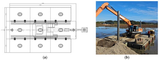
Figure 1.
General arrangement and field application of the modular barge. (a) General arrangement of the 15-ton-class modular barge composed of three modules—port, center, and starboard—connected through upper bolted and lower interlocking joints. (b) On-site photograph of the barge in operation, with a crawler excavator mounted on the deck for both work and propulsion.
2.2. Connection System and Modelling
The barge consists of three modules—port block, center block, and starboard block—assembled in a modular fashion that allows separation and re-connection. The modules are joined through two types of connections: upper bolted joints at the deck level and lower interlocking joints at the bottom. This dual connection system ensures adequate structural continuity while maintaining the advantages of easy assembly and disassembly.
At the deck level, bolted joints form the primary structural elements linking the port, center, and starboard modules (Figure 2a). A bolting plate attached to the hinge region of the center block is connected to the flanges of the side blocks. Each plate accommodates four high-strength bolts with a diameter of 36 mm. The bolting plate functions as the upper flange, whereas the side blocks provide the lower flange counterpart. To enhance stiffness, three rows of reinforcing ribs, each 16 mm thick and 28 mm high, are installed at 110 mm spacing. The bolting plate itself has a thickness of 20 mm, and 15 mm-thick steel plates are applied to the adjoining flange regions. Six bolted joints are arranged along each side of the center block, with four bolts per joint, resulting in a total of 48 bolts. This configuration provides sufficient strength to secure the modules and to distribute deck loads uniformly across the assembled hull (Figure 2b).
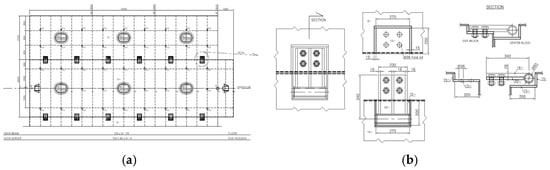
Figure 2.
General arrangement and upper connection of the modular barge. (a) Deck plan showing the layout of bolted joints connecting the port, center, and starboard modules. (b) Enlarged view of an upper bolted-joint assembly illustrating the bolting plate and reinforcing ribs that secure deck-level continuity.
At the bottom, interlocking joints are employed to maintain alignment and resist shear forces between modules (Figure 3a). Protruding ridges on the lower parts of the side blocks fit into recessed grooves of the center block, forming a tongue-and-groove type connection extending over 10 m in length. The interlocking geometry spans approximately 300 mm in the transverse direction and 240 mm in depth. To ensure adequate strength, the protruding side structures are reinforced with 9 mm thick stiffened plates aligned with the frame spacing, while the recessed grooves of the center block are fabricated from 12 mm thick plates. A detailed structural drawing of the interlocking joint is shown in Figure 3b.
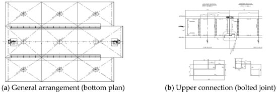
Figure 3.
General arrangement and bottom connection of the modular barge.
Based on the above connection systems, the entire barge was modeled according to the structural arrangement plan and midship section drawing, with accurate thicknesses assigned to each plate and stiffener. The detailed 3D models of the upper bolted joint and the bottom interlocking joint are presented in Figure 4 and Figure 5, respectively. Furthermore, a fully detailed 3D model of the entire barge, including internal structural members, was generated (Figure 6). The model weight was calculated as 38.19 tons, which closely agrees with the reference lightship weight of 38.16 tons, confirming the accuracy of the modeling.
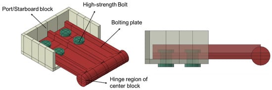
Figure 4.
Detailed 3D model of the upper bolted joint.
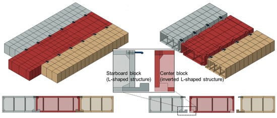
Figure 5.
Detailed 3D model of the bottom interlocking joint.
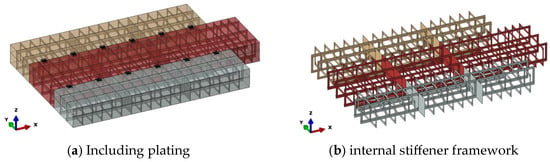
Figure 6.
Overall 3D structural model of the modular barge.
2.3. Material Properties
The primary material for the hull plating and stiffeners is structural steel (SM400), which is commonly used in small ship and barge construction. For the bolted connections, medium carbon steel (S45C) is employed, providing higher tensile strength suitable for fastening applications. The material properties used in the finite element analysis are listed in Table 2. The allowable stresses were determined according to KR rules with a safety factor of 1.5. For SM400 steel, the allowable stress was set to 157 MPa, while for S45C bolts, the allowable stress was 237 MPa. These criteria form the basis for evaluating the structural adequacy of the barge under the applied loading conditions.
Table 2.
Material properties used in the analysis.
3. Numerical Modelling and Analysis Procedure
3.1. Finite Element Model
Finite element analysis (FEA) was performed using ABAQUS/Standard 2021 to evaluate the global structural strength of the modular barge and to capture local stress distributions around the bolted connections. Contact interactions were explicitly defined for both upper bolted joints and lower interlocking joints, while inertia relief was employed to conduct static analyses under free-floating conditions. The hull structure, including deck, bottom, side shell, and internal stiffeners, was modeled using shell elements to represent global stiffness. The upper bolted joints (bolting plate, hinge part, bolts/nuts, and adjoining flange regions) were modeled with solid elements to resolve localized stress gradients. The lower interlocking joints (tongue-and-groove connections between center and side blocks) were represented through surface-to-surface contact to reflect realistic bearing and shear transfer. Bolted regions were discretized with refined hexahedral solid elements, while the remaining hull shells were meshed with a uniform grid of 100 × 100 mm. Representative FE models are illustrated in Figure 7a (global mesh), Figure 7b (internal stiffener arrangement), and Figure 7c (bolted joint detail).
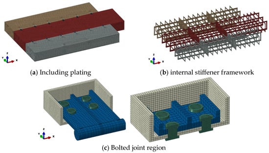
Figure 7.
Overall finite element model of the modular barge.
A summary of the finite element mesh configuration is provided in Table 3. The hull plating and stiffeners were discretized with shell elements (S4R) at a mesh size of 100 × 100 mm, resulting in 56,558 elements. The upper bolted joints were refined with solid hexahedral elements (C3D8R) using mesh sizes of 5–10 mm, producing 130,944 elements. The total number of elements in the complete structural model was 188,860, which ensured sufficient resolution of both global deformations and local stress concentrations.
Table 3.
Finite element mesh configuration for the modular barge.
The selected mesh density follows recognized practices recommended by classification societies and structural assessment guidelines [18,19]. In these standards, the typical shell-element size for ship and barge structures is approximately one-quarter of the representative stiffener spacing, while local refinement to the order of plate thickness is advised in stress-critical regions. Accordingly, the present model adopted 100 × 100 mm shell elements (≈¼ of the typical 400–500 mm stiffener spacing) and 5–10 mm solid elements near the bolted and interlocking joints, which provides mesh quality consistent with these recognized criteria.
3.2. Connection Modeling
The upper bolted joint and the lower interlocking joint were modeled with detailed contact and constraint definitions to capture their structural behavior accurately. For the upper bolted joint, the bolting plate (upper flange), hinge part integrated with the center block, high-strength bolts/nuts, and the adjoining flange regions of the port and starboard blocks were represented using solid elements. Contact interactions were defined with hard normal behavior and a tangential friction coefficient of μ = 0.3, applied to the interfaces between the bolt head and upper flange, nut and lower flange, flange-to-flange surfaces, and bolt shank and hole surfaces. The friction coefficient between steel contact surfaces was defined as μ = 0.3, which represents typical values for dry, unlubricated steel-to-steel interfaces according to the general contact-modeling recommendations of DNVGL-CG-0127: Finite Element Analysis [20]. The hinge region was tied to the center block to suppress relative displacement, and a shell-to-solid coupling was employed to ensure compatible displacements and rotations across the interface between the shell-modeled hull and the solid-modeled joint (Figure 8).
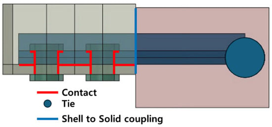
Figure 8.
Schematic of the connection modeling for the upper bolted joint.
The lower interlocking joint was represented as a tongue-and-groove system, in which protruding ridges on the side blocks engage recessed grooves of the center block over a longitudinal length of approximately 10 m, a transverse span of 300 mm, and a depth of 240 mm. To ensure sufficient strength, the protruding side structures were reinforced with 9 mm thick plates aligned with the frame spacing, while the recessed grooves were fabricated with 12 mm plates. Surface-to-surface contact was defined for the mating faces of the side and center blocks, thereby representing realistic bearing and shear transfer under operational loading.
3.3. Loading and Boundary Conditions
The structural assessment considered both still-water and dynamic loads to represent the working condition of the 15-ton-class modular barge. The principal hydrostatic condition is summarized in Table 4, with a displacement of 65.824 t at a draft of 0.566 m, comprising a lightship weight of 38.164 t and a deadweight of 27.660 t.
Table 4.
Hydrostatic and loading conditions for the modular barge analysis.
The deadweight is dominated by a crawler excavator (23.7 t) and an auxiliary mass (3.0 t), both positioned at the longitudinal center of gravity (LCG = 0.0 m). Still-water loads included the self-weight of the barge, bottom pressure on the bottom shell, hydrostatic pressure on the side shell, and deck pressure distributed over the excavator track footprints (0.7 m × 4.0 m × two tracks). These still-water loads are summarized in Table 5.
Table 5.
Still-water loads applied in the working condition.
To conservatively account for dynamic effects in inland and harbor service, a design wave height of 0.6 m was selected, consistent with reported significant wave heights of 0.3–0.6 m and recommended conservative practice. The corresponding maximum hydrostatic pressure was:
Dynamic conditions were reproduced using parabolic hydrostatic pressure fields applied to the bottom shell via ABAQUS Analytical Field definitions. For longitudinal bending (X-axis), sagging (crest condition) and hogging (trough condition) were represented by:
where L is the barge length and x is the longitudinal coordinate measured from mid-length.
For transverse bending (Y-axis), analogous parabolic distributions were used to evaluate stresses, particularly at the bolted joints:
where B is the barge breadth and y is the transverse coordinate from mid-breadth. These formulations provide a practical and conservative means of embedding dynamic effects without resorting to fully coupled fluid–structure interaction (Figure 9).
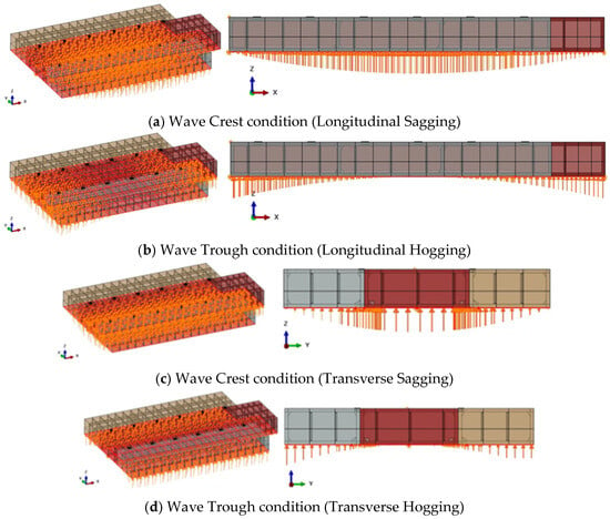
Figure 9.
Dynamic load distributions under wave crest and trough conditions.
Because the model represents a free-floating assembly with numerous contact interfaces, careful boundary treatment was essential. Inertia relief was adopted to suppress rigid-body motions while maintaining global force–moment equilibrium. This method counterbalances the applied external loads by distributing equivalent inertial forces, thereby allowing the barge to behave as a free-floating body without the need for artificial supports. A supplementary comparison with a partially constrained reference model confirmed that the use of inertia relief had negligible influence on the stress distribution at critical joints. To aid convergence, bolt heads were tied to adjoining flanges rather than applying fully nonlinear contact everywhere, which provided stable solutions while preserving realistic global behavior. Boundary constraints followed classification-society guidance for direct strength assessment [21], with a three-point constraint scheme applied to suppress rigid-body modes without over-constraining the structure.
3.4. Load Case Definition
To conservatively evaluate the structural response of the modular barge under realistic operating conditions, four representative load cases were defined by combining still-water loads with dynamic pressure fields corresponding to wave crest and trough scenarios. The dynamic wave height was set to H = 0.6 m, consistent with typical significant wave heights in inland and harbor waters (≈0.3–0.6 m) and recommended conservative practice for protected environments. According to DNV-RP-C205: Environmental Conditions and Environmental Loads [7], this range represents the typical environmental conditions for sheltered or near-shore regions, and adopting the upper bound (0.6 m) provides a conservative basis for evaluating structural integrity under wave-induced loads. Both longitudinal (X-axis) and transverse (Y-axis) directions were considered, with parabolic pressure fields representing sagging (crest) and hogging (trough) conditions. The still-water loads—lightship weight, deck loads from equipment, hydrostatic pressure on the side shell, and bottom pressure—were included in all cases. On top of these, wave-induced dynamic pressures were superimposed according to the conditions summarized in Table 6.
Table 6.
Definition of load cases for structural analysis.
This framework ensures that the analyses capture the combined effects of still-water loading and representative dynamic wave-induced bending, thereby providing a conservative basis for assessing global strength and local connection behavior. Although direct experimental validation could not be performed due to the full-scale and in-service nature of the analyzed barge, the present finite-element-based structural evaluation corresponds to the analysis formally reviewed and approved by a domestic maritime certification authority. The approved vessel is currently in service, providing indirect yet authoritative validation of the modeling framework adopted in this study.
4. Results
The structural response of the modular barge was evaluated under the four defined load cases (Table 6). Still-water loads were applied consistently across all cases, while dynamic wave-induced pressures were varied longitudinally and transversely to represent crest (sagging) and trough (hogging) conditions. The results are presented in terms of von Mises stresses, deformations, and safety margins with respect to allowable stresses.
Representative von Mises stress and displacement contours are shown in Figure 10 for Case 1 (longitudinal crest) and Figure 11 for Case 4 (transverse trough), which correspond to the most critical sagging and hogging conditions. In all cases, the maximum deformations were below 3 mm, concentrated near the center of the hull where deck loads and hydrodynamic pressures overlap. Stress contours confirmed that the overall load transfer was well distributed through the hull plating and internal stiffeners, with local concentration observed primarily at the connection interfaces.
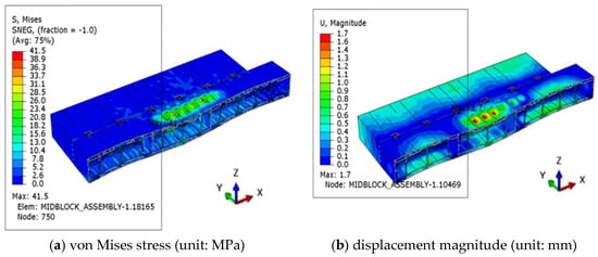
Figure 10.
Case 1 global structural response contour plot.
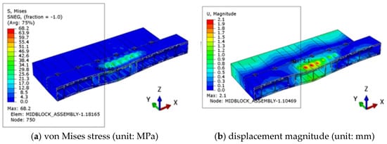
Figure 11.
Case 4 global structural response contour plot.
The upper bolted joints exhibited low stress levels in all cases. Even under the most unfavorable condition (Case 2—longitudinal trough), where global hogging deformation imposed the largest tensile demand on the connections, the maximum stress in the bolts was 34.1 MPa, corresponding to only 14.8% of the allowable value of 230 MPa, ensuring a safety factor greater than 6.7. The bolting and pin plates carried stresses in the range of 20–33 MPa, well within the allowable limits, confirming that the bolted connections effectively transfer deck loads without critical overstress. These results are illustrated in Figure 12, which shows the stress and displacement contours of the bolted connection under Case 2, clearly highlighting the localized stress concentrations yet demonstrating sufficient margins of safety.
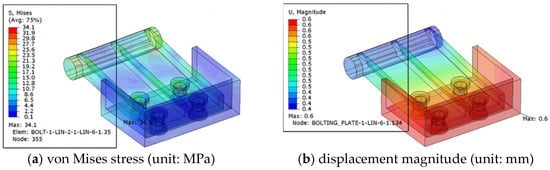
Figure 12.
Case 2 stress contours of the lower interlocking joints.
The lower interlocking joints experienced higher stresses compared to the bolted joints, particularly at the center block interface. The most severe condition occurred under Case 4 (transverse trough), where the maximum stress reached 68.2 MPa at the central interlocking interface. This represents 43.7% of the allowable 156 MPa, still ensuring a safety factor of 2.29. Side block interfaces carried much lower stresses (≤17.6 MPa), indicating that the interlocking geometry efficiently distributes shear and alignment loads. Figure 13 illustrates the stress distribution at the lower interlocking joint in Case 4, highlighting the concentration at the center block engagement while demonstrating adequate safety margins.
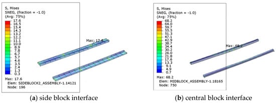
Figure 13.
Case 4 interlocking joint structural response contour plot.
For the central block, hull plating stresses ranged between 39 and 43 MPa depending on the wave condition, while the internal stiffeners showed peak stresses up to 48.7 MPa (Case 2). These values correspond to about 25–31% of the allowable stress (156 MPa), maintaining safety factors between 3.2 and 4.0. Side block plating and stiffeners generally carried much lower stresses (≤22 MPa), demonstrating that the central block governs the global strength.
The higher stresses observed in the interlocking joints originate from their local contact behavior, where partial constraint and geometric discontinuity lead to concentrated load transfer between modules. In contrast, the stiffeners act as the main longitudinal load-carrying members, forming continuous stress paths that govern the global bending response of the barge. Therefore, while the global deformation is primarily controlled by the stiffener system, local stress peaks arise near the joint interfaces due to contact pressure gradients and secondary bending effects.
Table 7 provides a quantitative overview of the maximum von Mises stresses and corresponding safety factors for the principal structural components under all four loading cases. The results show that the highest stresses were observed in the internal stiffeners and the lower central connection, yet these values remained comfortably within the allowable limits. Even in the most severe case, the minimum safety factor exceeded 2.3, ensuring sufficient structural margins. By contrast, the bolted joints consistently exhibited comparatively low stress levels, underscoring the redundancy and robustness of the combined bolted–interlocking system.
Table 7.
Summary of FEA results for Cases 1–4.
5. Conclusions
This study conducted a detailed structural evaluation of a 15-ton-class modular barge that has been constructed and is currently in operation. Unlike prior investigations that largely relied on conceptual or simplified models, the present analysis directly reflected the as-built configuration, including explicit representations of both bolted and interlocking joints. By doing so, it provided a rare and realistic assessment of the structural integrity of an operating modular barge under representative service loads.
Both still-water and dynamic wave-induced loads were incorporated, with four load cases formulated to represent longitudinal and transverse sagging and hogging responses. The results confirmed that the modular barge maintains sufficient safety margins in all cases, with maximum von Mises stress well below the allowable limits. Importantly, the analyses clarified the complementary load-sharing roles of the dual connection system: the lower interlocking joints resisted the majority of shear and bending demands, while the upper bolted joints enhanced continuity and stability, ensuring robustness of the overall assembly. This hybrid mechanism, quantified through finite element modeling, provides new insights into how modular connection systems function beyond simplified assumptions.
From an academic perspective, this work makes three main contributions. First, it demonstrates how the structural adequacy of modular floating systems can be rigorously verified using an actual in-service barge, supported by a third-party technical review conducted by a domestic marine safety authority, thereby providing empirical evidence that has been largely absent from the literature. Second, it addresses a gap in current barge design codes, which give little guidance on allowable stresses or design methodologies for modular connections, by offering case-based evidence that can inform future rules and guidelines. Third, it establishes a methodological framework that can be scaled up to larger modular platforms, offering a basis for optimizing connection configurations in more demanding offshore or coastal environments.
Future studies should expand this framework toward fatigue assessment under cyclic loading, scale-up applications for larger modular barges, and parametric optimization of connection geometries. These directions will not only strengthen the fundamental understanding of modular connection systems but also support the development of engineering guidelines for the wider adoption of modular barges in inland and coastal engineering practice.
Author Contributions
Conceptualization, C.L.; methodology, C.L. and J.L.; formal analysis, C.L.; software, C.L.; validation, C.L. and J.L.; investigation, J.L. and J.K.; resources, J.K.; writing—original draft preparation, C.L. and J.L.; writing—review and editing, J.K. and J.L.; visualization, J.L.; supervision, J.K. and J.L. All authors have read and agreed to the published version of the manuscript.
Funding
This research was supported by the Korea Institute of Marine Science & Technology Promotion (KIMST), funded by the Ministry of Oceans and Fisheries (RS-2024-00420021).
Data Availability Statement
Data are contained within the article.
Conflicts of Interest
The authors declare no conflicts of interest.
References
- Zhong, X.; Chen, H.; Zhang, M.; Wang, X.; Kang, X.; Chen, W. Structural systems for modular integrated construction: Review and comparative analyses. Adv. Struct. Eng. 2025, 28, 1927–1944. [Google Scholar] [CrossRef]
- Wang, Q.; He, C.; Ding, J.; Geng, Y.; Cheng, X.; Zhang, X.; Ni, X.; Wang, J.; Wu, Y. Numerical and experimental studies on hydroelastic responses of a multiply-connected domain tourism platform in head waves. Ocean Eng. 2024, 294, 116795. [Google Scholar] [CrossRef]
- Zakki, A.F.; Windyandari, A. The application of modular floating pontoon to support floods disaster evacuation system in heavily populated residential areas. Int. J. Sci. Eng. 2014, 7, 166–173. [Google Scholar] [CrossRef]
- Li, Y.; Ren, N.; Li, X.; Ou, J. Hydrodynamic analysis of a novel modular floating structure system integrated with floating artificial reefs and wave energy converters. J. Mar. Sci. Eng. 2022, 10, 1091. [Google Scholar] [CrossRef]
- Baars Modular Pontoon. Modular Pontoon Systems. Available online: https://www.baarsbv.com/modular-pontoon (accessed on 30 September 2025).
- Korean Register (KR). Rules for the Classification of Steel Barges; Korean Register of Shipping: Busan, Republic of Korea, 2023. [Google Scholar]
- DNV-RP-C205; Environmental Conditions and Environmental Loads. Det Norske Veritas: Oslo, Norway, 2019.
- Sembcorp Marine Ltd.; World Intellectual Property Organization. A Connector System for a Modular Floating Platform. Patent WO2008140422A1, 20 November 2008. [Google Scholar]
- Xie, B.; He, G.; Zhao, C.; Jing, P.; Kumar Pal, S.; Iijima, K.; Jin, R.; Chen, B.; Ghassemi, H. Experimental and numerical investigation on the hydroelastic response of barge and KVLCC2 ship. Ocean Eng. 2024, 307, 118081. [Google Scholar] [CrossRef]
- Cheng, X.; Li, S.; Wang, G. Experimental study on hydrodynamic characteristics of barge-type breakwaters under different mooring methods. J. Mar. Sci. Eng. 2023, 11, 1016. [Google Scholar] [CrossRef]
- Watanabe, E.; Utsunomiya, T.; Wang, C.M. Hydroelastic analysis of pontoon-type VLFS: A literature survey. Eng. Struct. 2004, 26, 245–256. [Google Scholar] [CrossRef]
- Brown, S.A.; Xie, N.; Hann, M.R.; Greaves, D.M. Investigation of wave-driven hydroelastic interactions using numerical and physical modelling approaches. Appl. Ocean Res. 2022, 129, 103363. [Google Scholar] [CrossRef]
- Sun, Y.; Lu, D.; Xu, J.; Zhang, X. A study of hydroelastic behavior of hinged VLFS. Int. J. Nav. Archit. Ocean Eng. 2018, 10, 170–179. [Google Scholar] [CrossRef]
- Choi, D.H.; Jeon, J.M.; Maeng, M.J.; Kim, J.H.; Nam, B.W. Experimental and numerical study on motion responses of modular floating structures with connectors in waves. Ocean Syst. Eng. 2024, 14, 277–299. [Google Scholar] [CrossRef]
- Jiang, C.; Li, Q.; Hu, P.; Zhang, G.; Jiang, S.; Ould El Moctar, A. Experimental analysis of wave–structure interaction for very large modular floating structures. Ocean Eng. 2025, 315, 119763. [Google Scholar] [CrossRef]
- Kang, H.Y.; Kim, M.H. Time-domain hydroelastic analysis with efficient load estimation for random waves. Int. J. Nav. Archit. Ocean Eng. 2016, 9, 277–289. [Google Scholar] [CrossRef]
- Ren, N.; Wu, H.; Liu, K.; Zhou, D.; Ou, J. Hydrodynamic analysis of a modular floating structure with tension-leg platforms and wave energy converters. J. Mar. Sci. Eng. 2021, 9, 424. [Google Scholar] [CrossRef]
- American Bureau of Shipping (ABS). Common Structural Rules for Bulk Carriers—Advisory Notes: Finite Element Analysis and Mesh Density Guidelines; American Bureau of Shipping: Houston, TX, USA, 2020; Available online: https://ww2.eagle.org (accessed on 25 October 2025).
- Ship Structure Committee (SSC). Guidelines for Evaluation of Marine Finite Element Analyses; SSC-475; Ship Structure Committee: Washington, DC, USA, 2020. [Google Scholar] [CrossRef]
- DNVGL-CG-0127; Finite Element Analysis. DNV GL AS: Høvik, Norway, 2017. Available online: https://rules.dnv.com/docs/pdf/DNVGL/CG/2017-06/DNVGL-CG-0127.pdf (accessed on 25 October 2025).
- Korean Register (KR). Guidance for the Application of Rules for Steel Ships, Part 3—Hull Structures, Appendix 3-2: Guidelines for Direct Strength Assessment; Korean Register: Busan, Republic of Korea, 2024. [Google Scholar]
Disclaimer/Publisher’s Note: The statements, opinions and data contained in all publications are solely those of the individual author(s) and contributor(s) and not of MDPI and/or the editor(s). MDPI and/or the editor(s) disclaim responsibility for any injury to people or property resulting from any ideas, methods, instructions or products referred to in the content. |
© 2025 by the authors. Licensee MDPI, Basel, Switzerland. This article is an open access article distributed under the terms and conditions of the Creative Commons Attribution (CC BY) license (https://creativecommons.org/licenses/by/4.0/).