Abstract
In the field of rotating machinery, such as marine propulsion shafting, magnetic bearing-supported propulsion systems have garnered significant attention due to their non-mechanical contact advantages. To address the problem that the design of magnetic bearing controllers, based on theoretical models, neglects the dynamic characteristics of practical components like power amplifiers and displacement sensors, making it difficult to achieve ideal performance in practical applications, this paper proposes a control method for Hybrid Magnetic Bearings (HMBs) that combines a time-domain identification model with robust control. The method first models the power amplifier, HMB, and displacement sensor as an equivalent single system and obtains its high-precision transfer function model by performing system identification on its time-domain data using the least squares method. Based on this foundation, a PID controller is designed using the loop-shaping method to enhance the system’s robustness and control performance. Both simulations and experiments on an HMB test rig confirmed the controller’s effectiveness. The system showed excellent levitation, dynamic stability, and disturbance rejection, with experimental results closely matching simulations. The experimental results are consistent with the simulation results. This method provides a practical and feasible technical approach for enhancing the control performance of magnetic bearing-supported propulsion shafting.
1. Introduction
As a primary mode of transportation in complex marine environments, ships require propulsion systems that deliver high efficiency and robust reliability [1]. Magnetic bearings, as high-performance non-contact devices, eliminate rotor contact and thereby suppress friction losses inherent to conventional mechanical bearings. This contactless nature significantly enhances propulsion efficiency. Furthermore, their low maintenance requirements and extended service life make them highly attractive for propulsion shafting and other marine rotating machinery [2,3].
Hybrid magnetic bearings (HMB) [4,5], which integrate active electromagnetic and passive permanent magnetic elements, provide greater load capacity, enhanced disturbance rejection, and actively controllable support—without increasing system volume. Due to spatial constraints in marine vessels, the improved output efficiency of HMBs renders them well-suited for practical marine applications. During operation, the propulsion shafting is subjected to highly dynamic external disturbances, such as wave-induced loads, which can lead to rotor imbalance or instability. Consequently, enhancing magnetic bearing control for stable rotor levitation and improved system stability under harsh sea conditions has become a major research priority.
Currently, most magnetic bearing controllers are still developed based on idealized theoretical models. However, these models often disregard the dynamic behaviors of practical components, including power amplifiers and displacement sensors, thereby compromising control performance in real-world applications [6]. System identification methods allow accurate modeling of practical system dynamics and offer a robust approach to addressing the limitations of purely theoretical models. By providing high-fidelity models, system identification enhances the consistency between simulation and practical behavior, thereby improving the reliability of Simulink-based controller design and strengthening the robustness and applicability of the overall control system.
The main contributions of this paper are as follows:
- (1)
- A novel hybrid approach integrating time-domain system identification with robust control is proposed, effectively addressing the limitations of conventional frequency-domain methods such as low modeling accuracy and poor real-time performance.
- (2)
- A unified equivalent system model is established by integrating the power amplifier, hybrid magnetic bearing (HMB), and displacement sensor, which optimizes control objectives and yields a high-accuracy transfer function model.
- (3)
- A loop-shaping-based PID controller is designed for the identified model, significantly enhancing system robustness and dynamic performance.
- (4)
- Comprehensive validation through co-simulation and experimental tests provides a practical and reliable technical solution for improving the control performance of magnetic-bearing-supported propulsion shaft systems.
2. Literature Review
In magnetic bearing research, system identification primarily focuses on two key directions. The first aims to identify stiffness and damping parameters to characterize the support properties of magnetic bearings. Jiang et al. proposed an online method to measure equivalent stiffness and damping without relying on the system’s transfer function. Using PID control as a case study, they examined how control parameters, excitation amplitude, and frequency affect these support characteristics. The results showed that the proposed method accurately identifies the equivalent stiffness and damping of active magnetic suspension systems in real time [7]. Jiang et al. also introduced a method to measure the equivalent stiffness and damping of an AMB–rotor system under multi-frequency excitation. Unlike traditional methods based on single-degree-of-freedom (SDOF) models, this method employs a multi-degree-of-freedom (MDOF) rotor model. Experiments validated the method’s effectiveness in identifying the equivalent dynamic parameters of the AMB–rotor system [8]. Zhou et al. proposed a method for identifying the stiffness and damping coefficients of a closed-loop AMB system based on the rotor’s unbalanced response. The identified parameters were incorporated into a finite element (FE) rotor model to construct a comprehensive rotor–AMB Experimental bench model. The simulated unbalanced responses at various rotational speeds were compared with experimental data, confirming the method’s accuracy [9]. Xu et al. developed a method to directly identify equivalent stiffness and damping from AMB electrical control models, validating the results via rotor dynamic responses. The study revealed that stiffness can be consistently identified via a complete control model, whereas damping estimation remains challenging due to the influence of eddy current losses—even with a precise model [10].
The second research direction focuses on identifying the transfer function of magnetic bearings and designing corresponding controllers. Zhong et al. applied a fractional-order system identification method to model a solid-core magnetic bearing. Based on this model, both integer-order and fractional-order controllers were designed. Comparative simulations and experiments demonstrated that the fractional-order controller considerably enhances both transient and steady-state performance [11]. Noshadi et al. investigated system identification and robust control for a multiple-input multiple-output (MIMO) active magnetic bearing system. Closed-loop identification was performed using a genetic algorithm-based weighted least squares method, yielding a frequency-weighted optimal model derived from frequency response data. Due to the low gain in cross-coupling channels at low frequencies, the MIMO system was approximated as multiple low-order single-input single-output (SISO) subsystems to simplify control design. SISO controllers, MIMO H2, and optimal controllers were designed based on the identified models and experimentally validated, demonstrating the effectiveness of the proposed control strategies [12]. Zhou et al. validated a solid-type AMB model incorporating eddy current effects via system identification. Experimental results confirmed that the identified model accurately captured the dynamic behavior of the AMB under voltage excitation [13]. Zhou L et al. focused on the control performance optimization of magnetic bearing systems. A frequency-domain identification method was used to model the real system, extract frequency characteristics, and obtain a precise third-order transfer function. Based on the identified model, a second-order-plus-integrator controller was subsequently designed. Experiments showed that the newly designed controller significantly reduced rotor displacement fluctuations during steady levitation, outperforming the original PID controller [6]. Song et al. addressed modeling challenges caused by prominent eddy current effects in solid axial magnetic bearings by employing a closed-loop frequency-domain identification method to model the hybrid bearing’s axial component. Because integer-order models inadequately capture phase behavior, the study further investigated fractional-order identification methods. Results indicated that the fractional-order model achieved greater amplitude and phase accuracy than its integer-order counterpart, given the same number of terms [14]. Wang et al. used orthogonal polynomial fitting to identify the rigid body and bending modes of the rotor system, subsequently establishing a controlled model of the magnetic bearing system. A robust controller was designed accordingly to improve system performance. Experimental results demonstrated favorable control performance, confirming the efficacy of model-based robust controller design [15].
Most conventional methods for identifying the transfer function of magnetic bearings rely on frequency-domain system identification. However, these methods often exhibit limited modeling accuracy and poor real-time performance in complex, practical systems. To overcome these limitations, this study proposes a hybrid control strategy that combines time-domain system identification with robust control for HMB systems.
3. Method
3.1. Application of HMBs in Ship Propulsion Shaft System
A schematic diagram of the ship propulsion shafting system supported by HMBs is shown in Figure 1 [16]. The shafting system is supported by one radial HMB and one combined radial-axial HMB.
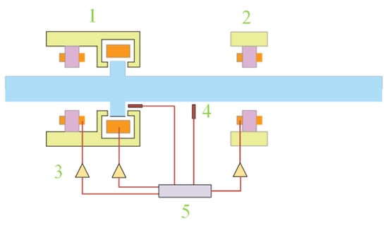
Figure 1.
Schematic structure of ship propulsion shaft system supported by hybrid magnetic bearing. 1—Radial-axial HMB, 2—Radial HMB, 3—power amplifier, 4—Displacement Sensor, 5—controller.
During the operation of a ship’s propulsion shafting system, external disturbances may cause deviations from its equilibrium position. To address this, displacement sensors continuously sample the rotor’s positional data. The acquired displacement signal is then preprocessed, including filtering, and transmitted to the controller. Based on a predefined control algorithm, the controller generates a control signal, which is amplified by a power amplifier and converted into a drive current. This current excites the electromagnetic coils, enabling the magnetic bearing to generate a corresponding electromagnetic force. This electromagnetic force acts on the propulsion shaft, driving the system back to its equilibrium position.
Throughout the entire process, the shaft and the HMB remain in a non-contact state, fundamentally eliminating friction-induced excitation caused by physical contact in conventional mechanical bearings. As a result, energy loss and mechanical noise are significantly reduced, thereby improving the system’s operational efficiency and overall stability.
3.2. System Identification
The precise transfer function of the HMB system is a critical component for achieving stable control, and accurate modeling of the system can be accomplished through system identification.
The principle of the HMB control system is shown in Figure 2.
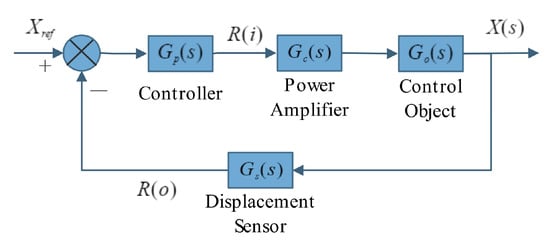
Figure 2.
Schematic diagram of the HMB control system.
Through system identification, with voltage R(i) as the input and displacement R(o) as the output, the transfer function of the signal passing through the power amplifier, HMB, and displacement sensor will be obtained. The new system control principle is shown in Figure 3.
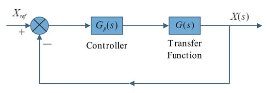
Figure 3.
Control schematic diagram of the equivalent system.
For continuous-time domain systems, their transfer function is given by
Since the system is a linear system, the least squares method is used for system identification to determine the transfer function. Its essence is to convert the transfer function into a difference equation and then use a linear regression model to fit the parameters, minimizing the sum of squared errors between the predicted output values from the model and the actual output values. Taking a second-order system as an example.
Assuming the transfer function of the continuous system is
The system is discretized using the backward Euler method:
where is the output, is the input, is the noise, and is the sampling time.
Let parameter vector , data vector , then
Rewrite N sets of data into matrix equations:
Note as
The objective function is
To minimize , find the parameter estimate value as
The HMB experimental bench includes two radial HMBs, positioned symmetrically on the left and right sides of the shaft. The structure of the radial HMB on both sides is identical, with each bearing comprising four magnetic poles. The magnetic poles are arranged in pairs and symmetrically distributed at 45-degree intervals. When equal positive voltages are simultaneously applied to both pole pairs, the resulting electromagnetic forces are equal in magnitude and oriented 90 degrees apart, producing a net force vertically upward. Therefore, under equal voltage excitation at both radial HMB, the rotor effectively exhibits single-degree-of-freedom motion in the vertical direction.
Using dSPACE as the controller, a voltage of V = 0.35 v is applied to both the left and right HMBs simultaneously, with a sampling frequency of 2k Hz. The vertical displacements of the rotors on both sides are recorded, and the relationship between the input voltage and the output displacement (voltage value) for each HMB is obtained. The dSPACE working interface is shown in Figure 4.
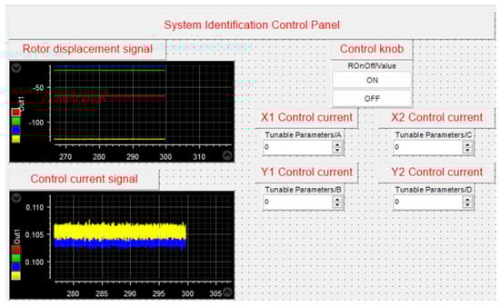
Figure 4.
dSPACE working interface diagram.
The input voltage and output displacement voltage data for the left HMB are shown in Figure 5, while those for the right HMB are shown in Figure 6. Here, u represents the input voltage value, and y represents the voltage value corresponding to the output displacement.
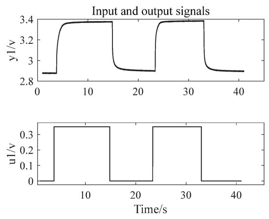
Figure 5.
The input voltage value and output displacement voltage value of the left HMB.
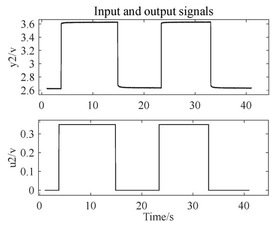
Figure 6.
The input voltage value and output displacement voltage value of the right HMB.
Due to the deviation between the input and output data, the data is processed to eliminate the deviation, making the data mean zero, as shown in Figure 7 and Figure 8.
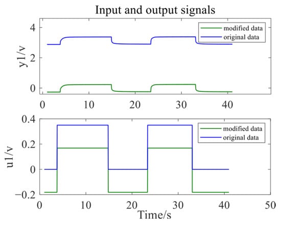
Figure 7.
Results after data processing of left HMB.
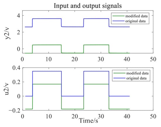
Figure 8.
Results after data processing of the right HMB.
The total data length is 40 s, with all data divided into two halves. The first 20 s of data are used as model estimation data, and the last 20 s of data are used as model validation data, as shown in Figure 9 and Figure 10.
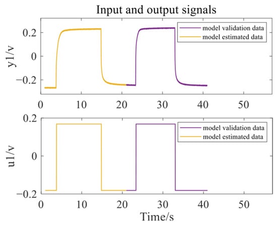
Figure 9.
Results after data classification of left HMB.
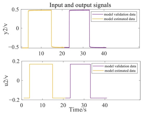
Figure 10.
Results after data classification of the right HMB.
The transfer function of the system is calculated by least squares method. Since the transfer function in Figure 3 is a “black box”, its transfer function is generally expressed in the form of
Assuming that the form of the “black box” transfer function is a second-order system, the transfer function of the left HMB is calculated according to the least squares method:
The transfer function of the right HMB is
The estimated output of the left HMB exhibits a fitting accuracy of 93.18% compared to the validation data, as shown in Figure 11. For the right HMB, the estimated output achieves a fitting accuracy of 98.05%, as shown in Figure 12.
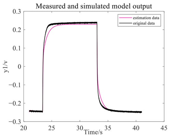
Figure 11.
The data fitting results on the left HMB.
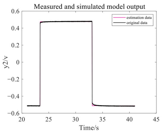
Figure 12.
The data fitting results on the right HMB.
The calculation results indicate that the fitting accuracy is relatively high, exceeding 80%. Therefore, the identified transfer function can be reasonably approximated as the equivalent transfer function of the HMB system.
3.3. Controller Design Based on Loop-Shaping Method
During the system identification phase, although the transfer function exhibits a high degree of fit, there is still a certain level of error. Therefore, it is necessary to enhance the robustness of the controller to achieve better control performance.
The loop-shaping methodology [17,18] systematically designs the frequency-domain characteristics of the open-loop transfer function and computes PID parameters through a mixed-sensitivity optimization framework. This approach embeds frequency-domain robustness constraints while preserving the structural simplicity of PID control, thereby ensuring both sufficient stability margins and maintained stability under parameter perturbations and external disturbances. The controller design methodology based on the loop-shaping approach is illustrated in Figure 13.
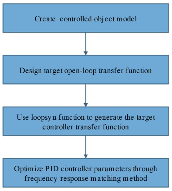
Figure 13.
Controller design ideas based on loop-shaping method.
In order to ensure low-frequency gain, while accelerating the system response speed and reducing dynamic overshoot, the integrated link and advance compensation link are added to the built open-loop transfer function. The design target bandwidth of the transfer function is 5 rad/s. The open-loop transfer function form is as follows:
where is the target bandwidth, takes the value of 3, and takes the value of 5.
By calling the loopsyn function, solve so that the actual open-loop transfer function approximates , that is, the infinite norms of and approximate 1.
Optimal when is 1.
After solving , the parameters of the PID controller are optimized by minimizing the amplitude and phase weighting errors according to the frequency response matching method. Right now:
Through the above method, the control parameters of the left HMB are = 2.029, = 73, = 1.2 × 10⁻⁵, N = 5 × 10³. The control parameters of the right HMB are = 0.41514, = 60, = 1.59 × 10⁻⁴, N = 2 × 10⁴.
Based on the obtained system transfer function and control parameters, the Nyquist plots of the closed-loop transfer functions for both HMB systems are plotted. The Nyquist plot of the closed-loop transfer function for the left HMB system is shown in Figure 14, and that for the right HMB system is shown in Figure 15.
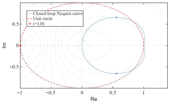
Figure 14.
Nyquist plot of the left HMB closed-loop control system.
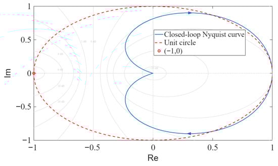
Figure 15.
Nyquist plot of the right HMB closed-loop control system.
As can be seen from the Nyquist plots in Figure 14 and Figure 15, the closed-loop transfer function poles of both HMB systems are located in the right-half plane of the unit circle, indicating that the systems are stable. This also demonstrates the effectiveness of the PID parameters obtained through the loop-shaping method.
3.4. dSPACE Control
dSPACE serves as a real-time simulation and control system development platform based on MATLAB (2024a version) [19]. It demonstrates significant advantages in magnetic suspension bearing control with its high-precision real-time control capabilities and efficient development process.
During the research process on magnetic suspension bearing control, importing the PID control algorithm model into the dSPACE platform allows for a rapid transition from algorithm simulation to hardware testing. In the experimental phase, the accompanying controlDesk software(2022b version) from dSPACE enables real-time monitoring of the rotor’s status. It synchronously visualizes signals such as rotor displacement and control current, and also features data acquisition capabilities. Through its intuitive visual interface, researchers can clearly observe changes in various parameters during the operation of the magnetic suspension bearing, providing strong support for subsequent data analysis and system optimization. By interacting with the controlDesk’s interactive interface, researchers can dynamically adjust PID control parameters, verify the robustness of the algorithm, and effectively shorten the debugging cycle.
The working principle of using the dSPACE platform for control is shown in Figure 16. By using a computer, the Simulink control model is compiled and downloaded to the dSPACE system, the magnetic bearing rotor displacement signal is connected to the ADC interface of the dSPACE platform as the system’s input, and then, based on the Simulink control model, control currents are generated and output through the DAC interface to the power amplifier.
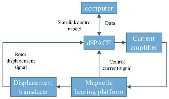
Figure 16.
The working principle diagram of the dSPACE platform.
4. Simulation
4.1. Establishment of Simulation Model
According to the control principle of the HMB system, a simulation model for the rotor fluctuation response is established, as shown in Figure 17. To avoid overloading the magnetic bearing due to excessive current, a current limiting module is incorporated into the model, with a range of . The rotor is initially stationary. The input signal is a step signal, which takes effect at 1 s with a magnitude of 1 A. A sinusoidal signal is added to simulate external disturbance forces, with an amplitude of 3 N and a frequency of 30 Hz, which takes effect after a delay of 2 s. The simulation model for the rotor response under external disturbance forces is established as shown in Figure 18.
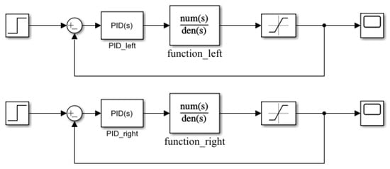
Figure 17.
Simulation Model of Rotor Fluctuation Response.
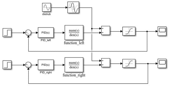
Figure 18.
Simulation Model of Rotor Response Under External Disturbance Forces.
4.2. Simulation Results and Analysis
- (1)
- Rotor fluctuation response.
Enter the transfer function in formulas (9) and (10) into the simulink model, and the simulation time is set to 2 s. The control parameters of the left magnetic bearing are = 2.029, = 73, = 1.2 × 10⁻⁵, N = 5 × 10³. The simulation results are shown in Figure 19. The control parameters of the magnetic bearing on the right are = 0.41514, = 60, = 1.59 × 10⁻⁴, N = 2 × 10⁴. The simulation results are shown in Figure 20.
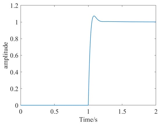
Figure 19.
Simulation result diagram of left HMB.
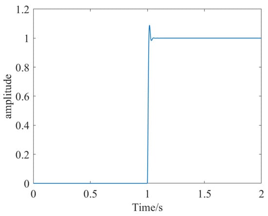
Figure 20.
Simulation result diagram of right HMB.
From the simulation results, we can see that the rise time is 0.0374 s, the adjustment time is 0.154 s, the overshoot is 7.4%, and the peak is 1.07. The left HMB system control parameters are reasonable and meet the control requirements.
From the simulation results, we can see that the rise time is 0.00915 s, the adjustment time is 0.0268 s, the overshoot is 9.02%, and the peak is 1.09. The right HMB system control parameters are reasonable and meet the control requirements.
- (2)
- The response of the rotor under external disturbance forces.
Under the influence of external disturbance forces, the control effect of the left rotor is shown in Figure 21 and Figure 22, while the control effect of the right rotor is shown in Figure 23 and Figure 24.
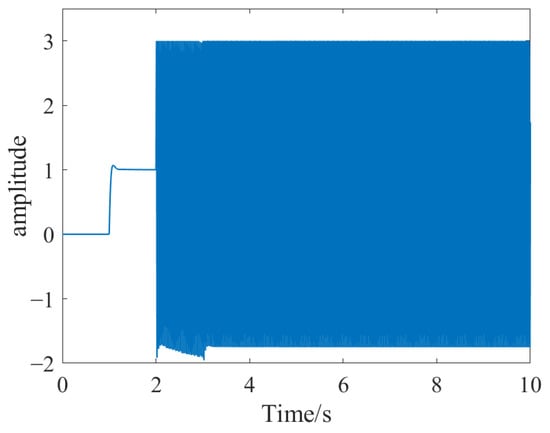
Figure 21.
Control effect diagram of the left rotor under external disturbance forces.
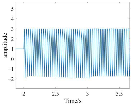
Figure 22.
Enlarged view of left rotor control effect.
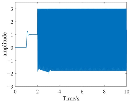
Figure 23.
Control effect diagram of the right rotor under external disturbance forces.
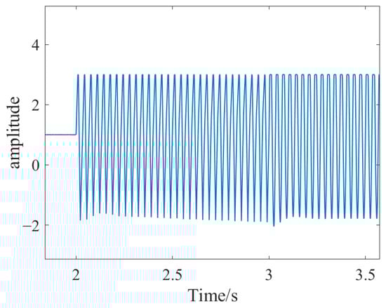
Figure 24.
Enlarged view of the right rotor control effect.
According to the simulation results, under the influence of external disturbance forces, the variation in rotor displacement does not exceed the system’s required threshold, and the control parameters are able to maintain stable levitation of the rotor.
5. Experiment
5.1. Experimental Bench
The HMB experimental bench is shown in Figure 25 [16].
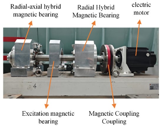
Figure 25.
Real picture of HMB experimental bench.
The experimental bench consists of two HMBs, one excitation magnetic bearing, a magnetic coupling, and a motor. The rotor is driven by the motor, and connected via a magnetically coupled shaft coupling, enabling the transmission of force and torque through magnetic interaction. The right side of the bench is supported by a radial-axial HMB, while the left side is supported by a radial HMB. The two radial HMBs share identical structural configurations. When the rotor is not in operation, it rests on mechanical backup bearings. During normal operation, the rotor is fully levitated by the two HMBs at both ends with no physical contact with the surroundings. The motor can adjust the rotor speed, with a speed range of 0~3000 rpm. All experiments were conducted under standard ambient temperature and pressure conditions without any special environmental requirements.
5.2. HMB Control Experiment
In combination with dSPACE, a control model is established using a Simulink model, with its control block diagram shown in Figure 26, where x1 represents the horizontal direction of the left HMB, y1 represents the vertical direction of the left HMB, x2 represents the horizontal direction of the right HMB, and y2 represents the vertical direction of the right HMB. The PID controller parameters for the x1 and y1 directions are as follows: = 2.029, = 73, = 1.2 × 10⁻⁵, N = 5 × 10³. The parameters of the PID controller of x2 and y2 directions are = 0.41514, = 60, = 1.59 × 10⁻⁴, N = 2 × 10⁴.
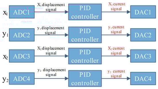
Figure 26.
Control model block diagram.
First, when the HMB is in a stationary state, use the aforementioned PID parameters to conduct the rotor levitation experiment, verifying the effectiveness of the PID parameters. Then, in the levitation state, change the motor speed to 500 rpm and 1000 rpm, respectively, observe the stability of the rotor levitation, and further validate the control performance. Finally, apply an external excitation force to the rotor by exciting the magnetic bearing to verify the system’s anti-interference capability. Utilize dSPACE to monitor the control performance and collect the changes in rotor displacement and the magnitude of the control current. The dSPACE monitoring interface is shown in Figure 27.
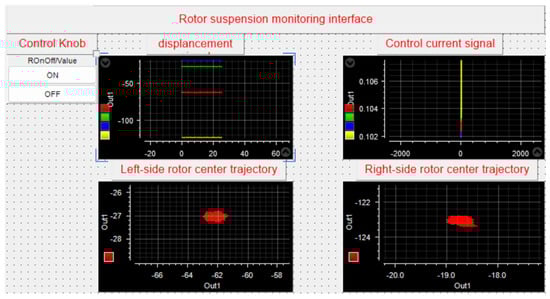
Figure 27.
dSPACE monitoring interface.
5.3. Experiment Results and Analysis
- (1)
- Rotor static suspension experiment.
When the rotor is in a stationary state, the controller initiates operation and records the displacement variation process of the rotor from the stationary state to the stable levitation state. The rotor displacement variations are shown in Figure 28 and Figure 29, where x1 represents the horizontal direction of the right rotor; y1 represents the vertical direction of the right rotor; x2 represents the horizontal direction of the left rotor; y2 represents the vertical direction of the left rotor.
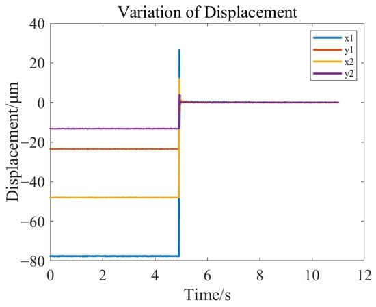
Figure 28.
Displacement change diagram during static suspension of rotor.
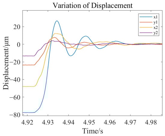
Figure 29.
Amplified displacement diagram of the rotor during static suspension.
From the static suspension experiment of the rotor, it can be observed that the system exhibits a rapid response speed, quickly reaching a stable state, and the fluctuation characteristics of the rotor are effective.
- (2)
- Dynamic stability Experiment.
Under the condition of stable rotor suspension, the motor speed was altered, and the displacement changes in the rotor at different speeds were recorded. When the speed stabilized at 500 rpm, the rotor displacement changes are shown in Figure 30 and Figure 31, the trajectory of the left rotor axis is depicted in Figure 32, and the trajectory of the right rotor axis is illustrated in Figure 33.
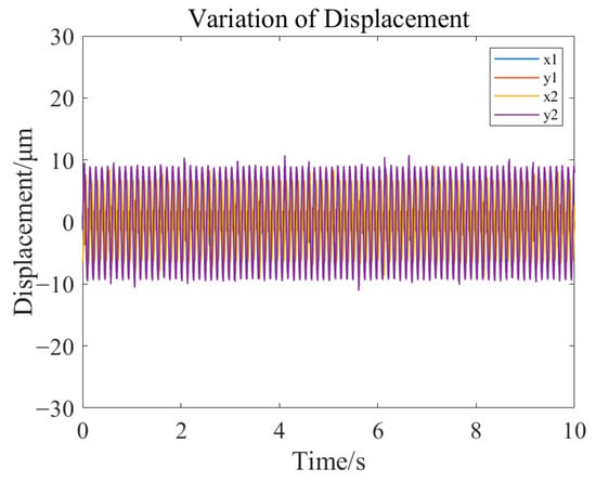
Figure 30.
Rotor displacement change diagram at 500 rpm.
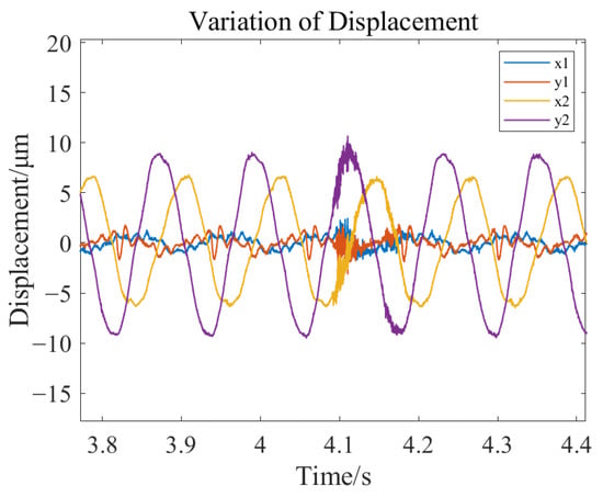
Figure 31.
Zoom in the rotor displacement change at 500 rpm.
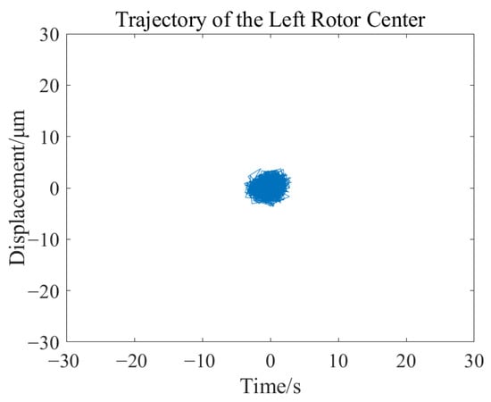
Figure 32.
Change diagram of the left rotor axis trajectory at 500 rpm.
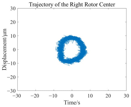
Figure 33.
Change diagram of the right rotor axis trajectory at 500 rpm.
Under the condition of stable rotor levitation, the motor speed was altered. When the speed stabilized at 1000 rpm, the changes in rotor displacement are shown in Figure 34 and Figure 35. The trajectory of the left rotor axis is depicted in Figure 36, and the trajectory of the right rotor axis is shown in Figure 37.
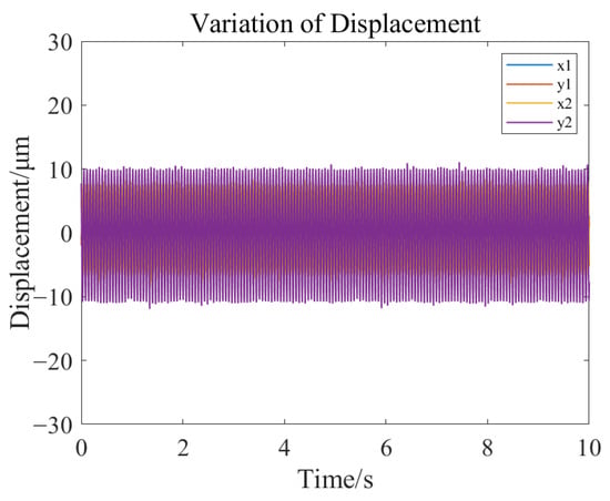
Figure 34.
Rotor displacement change diagram at 1000 rpm.
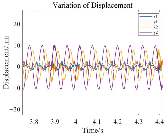
Figure 35.
Zoom in the rotor displacement change at 1000 rpm.
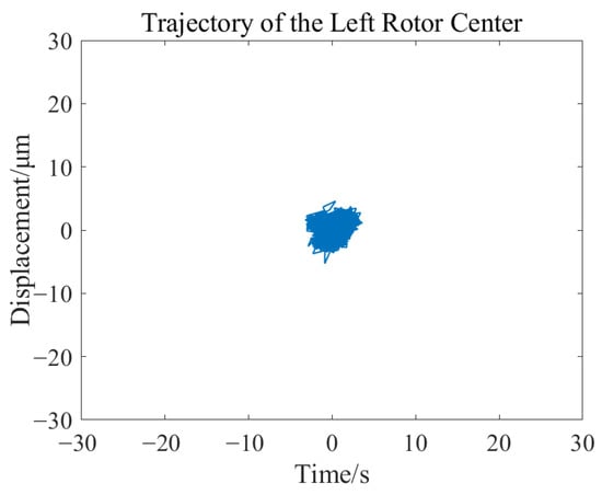
Figure 36.
Change diagram of the left rotor axis trajectory at 1000 rpm.
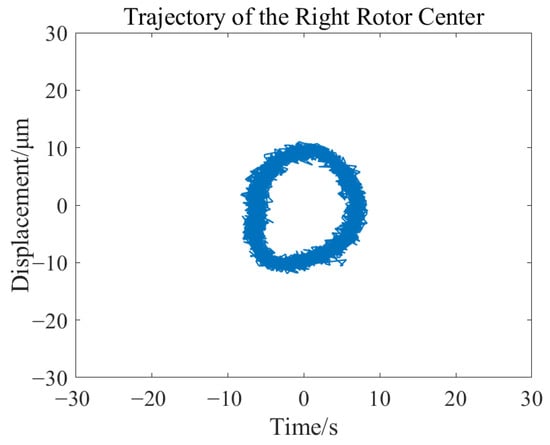
Figure 37.
Change diagram of the right rotor axis trajectory at 1000 rpm.
The results of the rotor dynamic stability experiment indicate that under operating conditions of 500 rpm and 1000 rpm, the rotor is capable of achieving stable levitation operation. The maximum displacement variation is less than 11 μm, which is significantly smaller than the air gap size of the magnetic bearings, fully meeting the engineering requirements for position control accuracy.
- (3)
- Anti-interference experiment.
In the state of stable rotor levitation, a sinusoidal external disturbance force is applied to the rotor through the excitation magnetic bearing on the experimental bench (as shown in Figure 25). The excitation magnetic bearing does not make contact with the rotor but acts on the rotor through electromagnetic force. The amplitude of the disturbance force is 0.3 A, with a frequency of 30 Hz, and the direction is vertical. The changes in rotor displacement are shown in Figure 38 and Figure 39.
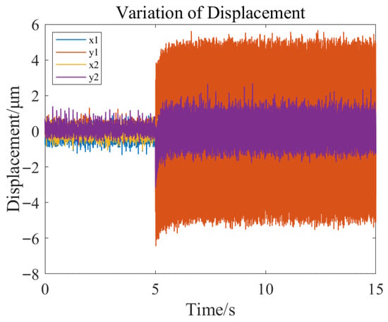
Figure 38.
Rotor displacement variation under external disturbance forces.
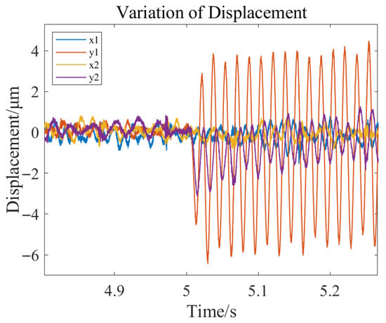
Figure 39.
Partial Enlarged View of Rotor Displacement under External Disturbance Force.
As illustrated in the figure, under the influence of external disturbance forces in the vertical direction, the rotor exhibits minimal impact on the horizontal displacement of both sides, whereas a significant effect is observed on the vertical displacement. The maximum variation in vertical displacement does not exceed 6 μm, which is considerably less than the air gap value. These results validate that the designed PID controller possesses excellent control performance, effectively suppressing external disturbances and maintaining system stability. Additionally, the experiments further substantiate the efficacy and feasibility of the hybrid control method proposed in this paper, which combines a time-domain system identification model with a robust control strategy in the magnetic bearing system. This provides a theoretical foundation and technical support for the engineering application of magnetic bearings in marine propulsion shafting systems.
6. Conclusions
To enhance control performance of HMB in supporting marine propulsion shafting, this paper proposes a hybrid control strategy that integrates time-domain system identification with robust control. The power amplifier, HMB, and displacement sensor are modeled as a single equivalent system. A high-accuracy transfer function model is identified using the least squares method based on time-domain response data. Based on the identified model, a PID controller is designed using loop-shaping techniques. The controller’s performance is verified through simulations conducted on the Simulink platform. Rotor levitation, dynamic stability, and disturbance rejection experiments were conducted on a HMB experimental bench. Experimental results demonstrate that the system exhibits favorable levitation and stability under various operating conditions, with strong disturbance rejection capability. Rotor displacement remains within a small fluctuation range, meeting engineering control requirements. Moreover, experimental results are consistent with simulation outcomes.
In summary, the proposed system identification approach effectively addresses the limitations of traditional theoretical models that overlook the influence of components such as power amplifiers and displacement sensors, thereby providing a more accurate representation of the actual system. The method has demonstrated excellent control performance, stability, and interference rejection in practical experiments. These results validate its feasibility and practical significance in HMB applications, offering a viable solution for improving control performance and operational reliability in marine propulsion shafting systems.
Although this study systematically investigates the proposed hybrid control method combining time-domain identification and robust control through theoretical analysis, simulation, and experimental validation—with promising results—the limitations of the experimental setup hinder the simulation of complex external excitations, such as nonlinear disturbances. Future work will incorporate more realistic disturbance sources to further improve the engineering applicability of the proposed control strategy.
Author Contributions
Conceptualization, Y.L.; Methodology, F.X., T.Y. and N.Z.; Software, F.X. and T.Y.; Formal analysis, Y.L.; Investigation, T.Y. and N.Z.; Data curation, W.X.; Writing—original draft, F.X.; Writing—review & editing, F.X. and W.X.; Project administration, N.Z.; Funding acquisition, Y.L. All authors have read and agreed to the published version of the manuscript.
Funding
This research received no external funding.
Data Availability Statement
The original contributions presented in this study are included in the article. Further inquiries can be directed to the corresponding author.
Conflicts of Interest
The authors declare no conflict of interest.
References
- Vizentin, G.; Vukelic, G.; Murawski, L.; Recho, N.; Orovic, J. Marine propulsion system failures—A review. J. Mar. Sci. Eng. 2020, 8, 662. [Google Scholar] [CrossRef]
- Du, Y.; Zhang, G.; Hua, W. Review on Research and Development of Magnetic Bearings. Energies 2025, 18, 3222. [Google Scholar] [CrossRef]
- Dutta, D.; Kumar Biswas, P.; Debnath, S.; Ahmad, F. Advancements and Challenges in Active Magnetic Bearings: A Comprehensive Review of Performance, Control, and Future Prospects. IEEE Access 2025, 13, 3051–3071. [Google Scholar] [CrossRef]
- Wang, H.; Wu, Z.; Liu, K.; Wei, J.; Hu, H. Modeling and Control Strategies of a Novel Axial Hybrid Magnetic Bearing for Flywheel Energy Storage System. IEEE/ASME Trans. Mechatron. 2022, 27, 3819–3829. [Google Scholar] [CrossRef]
- Liu, G.; Zhu, H. Displacement Estimation of Six-Pole Hybrid Magnetic Bearing Using Modified Particle Swarm Optimization Support Vector Machine. Energies 2022, 15, 1610. [Google Scholar] [CrossRef]
- Zhou, L.; Gan, Y.J. Model identification and control of a magnetic bearing system. Bearing 2021, 1, 1–6. (In Chinese) [Google Scholar] [CrossRef]
- Jiang, K.J.; Zhu, C.S. Online measurement of support characteristics in active magnetic suspension systems without known transfer functions. China Mech. Eng. 2010, 21, 883–888. (In Chinese) [Google Scholar]
- Jiang, K.; Zhu, C.; Chen, L.; Qiao, X. Multi-DOF rotor model based measurement of stiffness and damping for active magnetic bearing using multi-frequency excitation. Mech. Syst. Signal Process. 2015, 60–61, 358–374. [Google Scholar] [CrossRef]
- Zhou, J.; Di, L.; Cheng, C.; Xu, Y.; Lin, Z. A rotor unbalance response based approach to the identification of the closed-loop stiffness and damping coefficients of active magnetic bearings. Mech. Syst. Signal Process. 2016, 66–67, 665–678. [Google Scholar] [CrossRef]
- Xu, Y.; Zhou, J.; Jin, C. Identification of dynamic stiffness and damping in active magnetic bearings using transfer functions of electrical control system. Mech. Sci. Technol. 2019, 33, 571–577. [Google Scholar] [CrossRef]
- Zhong, J.; Li, L. Fractional-order system identification and proportional-derivative control of a solid-core magnetic bearing. ISA Trans. 2014, 53, 1232–1242. [Google Scholar] [CrossRef] [PubMed]
- Noshadi, A.; Shi, J.; Lee, W.S.; Shi, P.; Kalam, A. System identification and robust control of multi-input multi-output active magnetic bearing systems. IEEE Trans. Contr. Syst. Technol. 2016, 24, 1227–1239. [Google Scholar] [CrossRef]
- Zhou, L.; Li, L. Modeling and identification of a solid-core active magnetic bearing including eddy currents. IEEE/ASME Trans. Mechatron. 2016, 21, 2784–2792. [Google Scholar] [CrossRef]
- Song, X.T.; Deng, Z.Q. Modeling of an axial magnetic bearing based on system identification. Electr. Mach. Control 2024, 28, 76–84. (In Chinese) [Google Scholar] [CrossRef]
- Wang, Y.Y.; Zhou, J.; Xu, Y.P.; Zhou, Y.; Zhang, Y.B. System identification and robust control of a magnetic bearing system. Mach. Manuf. Autom. 2024, 53, 204–208. (In Chinese) [Google Scholar] [CrossRef]
- Xiong, F.; Li, Y.; Han, J. Method and Experimental Study of Axial Vibration Suppression of Propulsion Shaft System Supported by Hybrid Magnetic Bearings. Ocean Eng. 2024, 313, 119413. [Google Scholar] [CrossRef]
- Kobaku, T.; Jeyasenthil, R.; Sahoo, S.; Ramchand, R.; Dragicevic, T. Quantitative feedback design-based robust PID control of voltage mode controlled DC-DC boost converter. IEEE Trans. Circuits Syst. 2021, 68, 286–290. [Google Scholar] [CrossRef]
- Zhang, N.-W.; Peng, C.-C. Loop Shaping-Based Attitude Controller Design and Flight Validation for a Fixed-Wing UAV. Drones 2025, 9, 697. [Google Scholar] [CrossRef]
- Ren, G.-P.; Chen, Z.; Zhang, H.-T.; Wu, Y.; Meng, H.; Wu, D.; Ding, H. Design of interval type-2 fuzzy controllers for active magnetic bearing systems. IEEE/ASME Trans. Mechatron. 2020, 25, 2449–2459. [Google Scholar] [CrossRef]
Disclaimer/Publisher’s Note: The statements, opinions and data contained in all publications are solely those of the individual author(s) and contributor(s) and not of MDPI and/or the editor(s). MDPI and/or the editor(s) disclaim responsibility for any injury to people or property resulting from any ideas, methods, instructions or products referred to in the content. |
© 2025 by the authors. Licensee MDPI, Basel, Switzerland. This article is an open access article distributed under the terms and conditions of the Creative Commons Attribution (CC BY) license (https://creativecommons.org/licenses/by/4.0/).