Article

Implications of Flume Simulation for the Architectural Analysis of Shallow-Water Deltas: A Case Study from the S Oilfield, Offshore China

1
Key Laboratory of Exploration Technologies for Oil and Gas Resources, Ministry of Education, Yangtze University, Wuhan 430100, China
2
School of Geosciences, Yangtze University, Wuhan 430100, China
3
Tianjin Branch, China National Offshore Oil Corporation, Tianjin 300452, China
*
Authors to whom correspondence should be addressed.
J. Mar. Sci. Eng. 2025, 13(11), 2095; https://doi.org/10.3390/jmse13112095
Submission received: 17 September 2025 / Revised: 20 October 2025 / Accepted: 1 November 2025 / Published: 3 November 2025
(This article belongs to the Section Geological Oceanography)

Abstract

The shallow-water delta-front reservoir in Member II of the Oligocene Dongying Formation (Ed2), located in an oilfield within the Bohai Bay Basin, is a large-scale composite sedimentary system dominated by subaqueous distributary channels and mouth bars. Within this system, reservoir sand bodies exhibit significant thickness, complex internal architecture, poor injection–production correspondence during development, and an ambiguous understanding of remaining oil distribution. To enhance late-stage development efficiency, it is imperative to deepen the understanding of the genesis and evolution of the subaqueous distributary channel–mouth bar system, analyze the internal reservoir architecture, and clarify sand body connectivity relationships. Based on sedimentary physical modeling experiments, integrated with core, well logging, and seismic data, this study systematically reveals the architectural characteristics and spatial stacking patterns of the mouth bar reservoirs using Miall’s architectural element analysis method. The results indicate that the study area is dominated by sand-rich, shallow-water delta front deposits, which display a predominantly coarsening-upward character. The main reservoir units are mouth bar sand bodies (accounting for 30%), with a vertical stacking thickness ranging from 3 to 20 m, and they exhibit lobate distribution patterns in plan view. Sedimentary physical modeling reveals the formation mechanism and stacking patterns of these sand-rich, thick sand bodies. Upon entering the lake, the main distributary channel unloads its sediment, forming accretionary bodies. The main channel then bifurcates, and a new main channel forms in the subsequent unit, which transports sediment away and initiates a new phase of deposition. Multi-phase deposition ultimately builds large-scale lobate complexes composed of channel–mouth bar assemblages. These complexes exhibit internal architectural styles, including channel–channel splicing, channel–bar splicing, and bar–bar splicing. Reservoir architecture analysis demonstrates that an individual distributary channel governs the formation of an individual lobe, whereas multiple distributary channels control the development of composite lobes. These lobes are laterally spliced and vertically superimposed, exhibiting a multi-phase progradational stacking pattern. Dynamic production data analysis validates the reliability of this reservoir architecture classification. This research elucidates the genetic mechanisms of thick sand bodies in delta fronts and establishes a region-specific reservoir architecture model. This study clarifies the spatial distribution of mudstone interlayers and preferential flow pathways within the composite sand bodies. It provides a geological basis for optimizing injection–production strategies and targeting residual oil during the ultra-high water-cut stage. The findings offer critical guidance for the efficient development of shallow-water delta front reservoirs.

1. Introduction

Shallow-water deltas, known for their widespread sand bodies and superior reservoir quality, continue to attract significant research attention in petroleum geology [1,2,3]. Based on sediment grain size and composition, shallow-water deltas can be classified into two types: sand-rich and mud-rich [4,5]. Mud-rich shallow-water deltas, featuring low sand content and thin sand bodies, are widely developed in the Ordos Basin [6], Songliao Basin [7,8], and Bohai Bay Basin [9,10]. Researchers have established a relatively systematic framework of methods for studying these reservoirs.
In contrast, the sand-rich shallow-water deltas proposed in recent years has become one of the primary research focuses due to their favorable reservoir properties [11,12,13]. These systems feature high sand content, thick sand layers, making them prone to forming high-quality reservoir units. While their quality is favorable, they are also controlled by multi-stage sedimentary superimposition and erosional modification. These reservoirs commonly exhibit multi-story sand body stacking vertically and lateral sand body splicing horizontally. The presence of muddy interbeds further results in generally moderate connectivity. Furthermore, the genetic mechanisms of these interbeds are poorly constrained, making it difficult to delineate their spatial morphology—a limitation that severely hampers precise reservoir characterization and remaining oil prediction.
Existing studies on these specific reservoirs primarily concentrate on aspects such as sand body distribution characteristics, seismic response features, and hydrocarbon accumulation patterns. For instance, Zhou Donghong et al. [14] proposed a stepwise spectral inversion workflow to finely characterize the “sand-rich” extremely shallow-water deltaic, super-thick reservoirs in the Neogene strata of the Bohai Sea. Gao Lei et al. [15], employing seismic sedimentology theory, spectral decomposition inversion, and seismic attribute analysis, found that the distribution of sand-rich reservoirs in the Minghuazhen Formation (Lower Member) on the Shaleitian Uplift in the western Bohai Bay Basin is controlled by the coupling of “ridge-fault-sand” factors, with hydrocarbons accumulating in a “zigzag” pattern. Ma Jiaguo et al. [16] proposed a new sand body depositional model for sand-rich reservoirs in the Minghuazhen Formation (Upper Member) of Oilfield A in the Bohai Sea, subdividing the composite sand bodies into three stages of lobe deposits and unifying the oil-water contacts. Rossi’s et al. [17] outcrop study of the Jurassic Lajas Formation demonstrated that intense tidal reworking occurred in the distal front of this sand-rich, mixed-energy delta, forming extensive amalgamated sandstone bodies—a process unpredictable from coeval proximal records and likely controlled by syndepositional tectonic activity. Valencia et al. [18], through numerical modeling of fluvial-dominated deltas using a grain-size-dependent compaction algorithm, concluded that syn-sedimentary compaction creates additional accommodation space in the delta top, leading to increased sediment retention, a smoother coastline, and a more semi-circular delta shape, with these effects being more pronounced in mud-rich deltas.
Regarding fine reservoir characterization, previous researchers have conducted substantial work in S Oilfield. Zhang Xuefang et al. [19] employed a hierarchical constraint method to divide sedimentary stages and established an isochronous stratigraphic framework for individual sand bodies. By identifying lateral contact interfaces between individual sand bodies, they identified individual subaqueous distributary channels and mouth bar sand bodies within the same stage. This enabled the mapping of the planar distribution characteristics of contemporaneous but different architectural elements, forming a set of reservoir architecture research methods and techniques with offshore characteristics for delta front reservoirs. Xu Zhenhua et al. [20] finely characterized the distribution of internal foreset beds within mouth bars in S Oilfield through architectural interface modeling. Li Junfei et al. [21] statistically analyzed reservoir quality differences under different architectural units in S Oilfield, clarifying the distribution characteristics of remaining oil between layers and within layers influenced by reservoir architecture. Previous studies have systematically established a reservoir architecture characterization framework for S Oilfield, achieving significant results in establishing isochronous frameworks for individual sand bodies, identifying lateral contact interfaces, fine-scale modeling of internal mouth bar foresets, and understanding reservoir quality differences and remaining oil distribution patterns controlled by architectural units. Together, these form a technical series for fine characterization of offshore delta-front reservoirs.
Despite foundational research on the S Oilfield, the detailed characterization of its sand-rich shallow-water delta reservoirs still faces challenges due to their complex internal sand body stacking patterns and the frequent development of interbeds between sand bodies. Problems such as the difficulty in identifying individual sand bodies, the multiplicity of solutions in dividing architectural units, and an unclear understanding of the remaining oil distribution remain. Even under conditions of dense well patterns, fine-scale sand body delineation is challenging, constraining the improvement of later-stage oilfield development.
Therefore, this study utilizes physical sedimentary simulation to systematically investigate the genetic mechanisms and architectural patterns of sand-rich shallow-water delta reservoirs. To this end, we dissect the internal architecture of typical sand bodies to clarify their connectivity. This analysis is combined with dynamic production data for validation. Based on this foundation, our ultimate goal is to establish a dedicated architecture analysis framework for such reservoirs to enable efficient mid-to-late-stage oilfield development.

2. Regional Geological Setting

The Bohai Bay Basin, a Meso-Cenozoic intracontinental rift basin in eastern China, underwent its primary sedimentary filling from the Paleogene to Neogene. Its formation was fundamentally controlled by two major tectonic processes: the destruction of the North China Craton and the far-field effects of Pacific Plate subduction. The basin exhibits a characteristic multi-depression and multi-uplift structural framework, with major secondary units including the Jiyang Depression, Huanghua Depression, Bozhong Depression, and Cangxian Uplift. This structural architecture is extensively dissected by deep-seated fault systems like the Tan-Lu Fault Zone, which resulted in intense extensional and strike-slip superimposed deformation (Figure 1a) [22,23,24,25].
S Oilfield, located in the western Liaodong Depression, is a NE-trending fault-nose structure forming a structural-lithological reservoir over a buried hill. Hydrocarbon accumulation is controlled by structure and high-quality sandstone under normal pressure [26,27].
The main reservoir is Dongying Formation Member 2 (Oil Groups I and II) [28], between −1175 m and −1605 m depth (Figure 1b), with 14 sub-layers. It consists mainly of fine-grained sandstone with high porosity (31%) and permeability (2800 mD) (Figure 1c) [29].
Deposited in a fluvial-dominated delta front, the reservoir shows strong vertical heterogeneity. Sand body distribution is influenced by sedimentary microfacies, with multi-stage channels and internal permeability barriers affecting flow efficiency.

3. Data Analysis

3.1. Facies Identification

Based on systematic core observation data from five cored wells totaling 589.13 m in the study area, and integrating facies indicators such as sedimentary sequence characteristics, sedimentary structure types, and lithological associations, the identification and classification of sedimentary facies in Member 2 of the Dongying Formation were conducted.
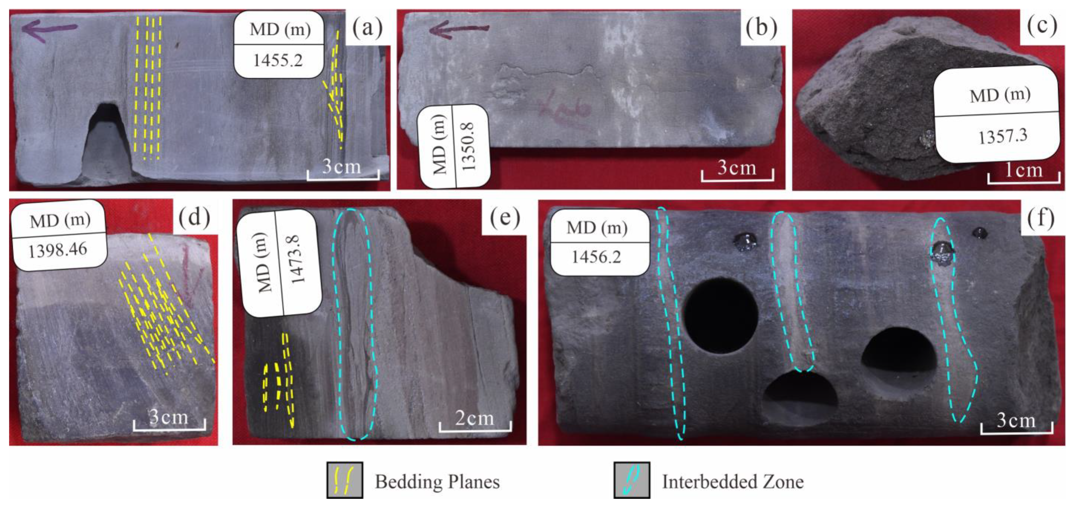
Sandstone and mudstone interbeds are frequently developed in the area. Mudstones predominantly exhibit grayish-green to light gray hues, indicating a subaqueous reducing environment. Sandstones are mainly light gray, fine-grained, with moderately good sorting and subangular to subrounded grain roundness. Internally, they display diverse sedimentary structures, including parallel bedding (Figure 2a), massive bedding (Figure 2b), cross-bedding (Figure 2d), lenticular bedding (Figure 2e), and deformation structures (Figure 2e).
Parallel bedding (Figure 2a) primarily develops in high-energy subaqueous distributary channel depositional environments [30].
Trough cross-bedding (Figure 2a) represents strong fluvial action, reflecting rapid deposition under energetic flow conditions associated with channel incision or lateral migration [31].
Massive bedding reflects the characteristic of rapid sediment accumulation [32]. Its base often exhibits a sharp contact with underlying muddy deposits (Figure 2b). This structure is widespread in shallow-water deltas and is generally associated with sheet sand deposits.
Lenticular bedding (Figure 2e) mainly develops in sand-mud interbeds under weak hydrodynamic conditions with insufficient sand supply, commonly observed in the delta front [33,34].
Deformation structures (Figure 2e) frequently develop in unconsolidated sediments, commonly found within sand-mud interbeds. They are often associated with slope environments, such as the delta front [35].
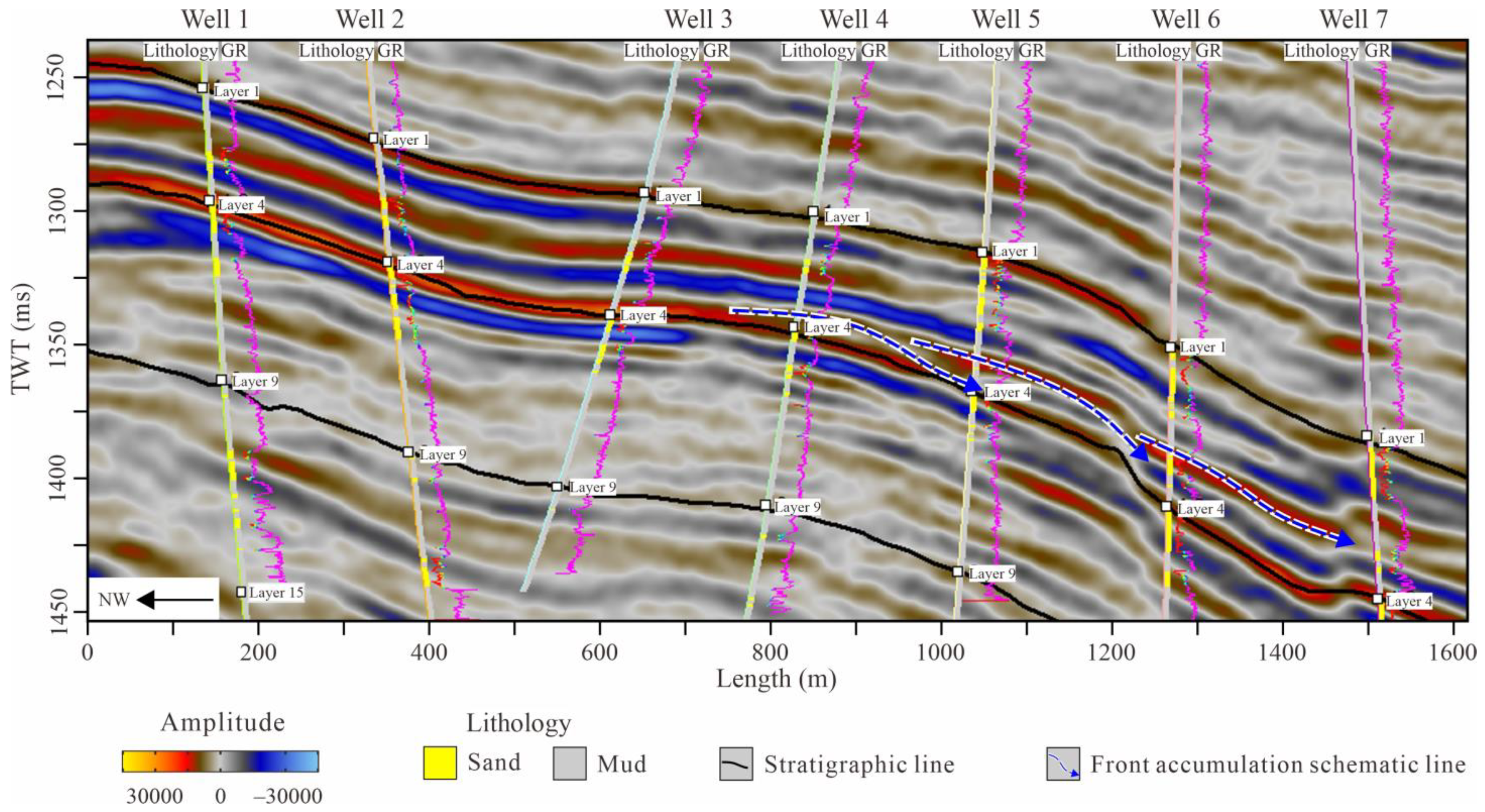
Based on well log characteristics in the study area, the gamma-ray (GR) curves predominantly exhibit a coarsening-upward (funnel-to-box-shaped) motif (Figure 3) [36]. Integrated analysis of resistivity, acoustic transit time, and other well-log data reveals a coarsening-upward sequence within the studied interval, manifested by a gradual increase in sediment grain size from base to top, reflecting a progressive strengthening of hydrodynamic conditions; concurrently, the sediment thickness increases with the progradation of the mouth bar, indicating an increase in accommodation space.
Using Vertical Seismic Profile (VSP) data and synthetic seismograms for calibration, a distinct progradational reflection configuration was identified on seismic sections. This progradational unit displays an S-shaped oblique pattern, advancing basinward. Its reflection terminations downlap distally, forming angular contacts with the underlying mudstone (Figure 4).
During the Paleogene (Shahejie to Dongying Formations), the S Oilfield basin developed under NE extensional faulting, forming a half-graben [37]. Early rifting (Shahejie) deposited deep-lake mudstones (source rocks), while wave and current reworking in shallow zones formed high-quality delta-front reservoirs. Later (Dongying), weaker tectonism led to gentler topography, with widespread shore-shallow lake and deltaic deposits. Sand bodies stacked vertically along slope belts due to confinement by fault troughs [38]. Paleo-highs and nose structures acted as barriers, concentrating sand along slope breaks and forming thick delta-front reservoirs [39].
Based on lithofacies analysis, well log characteristics, seismic profiles, and previous studies, the study area is interpreted as a shallow-water delta-front depositional system. Within this system, the following sedimentary microfacies are included: subaqueous distributary channels, mouth bars (including bar center and bar fringe), and interdistributary bay.

3.2. Microfacies Characteristics

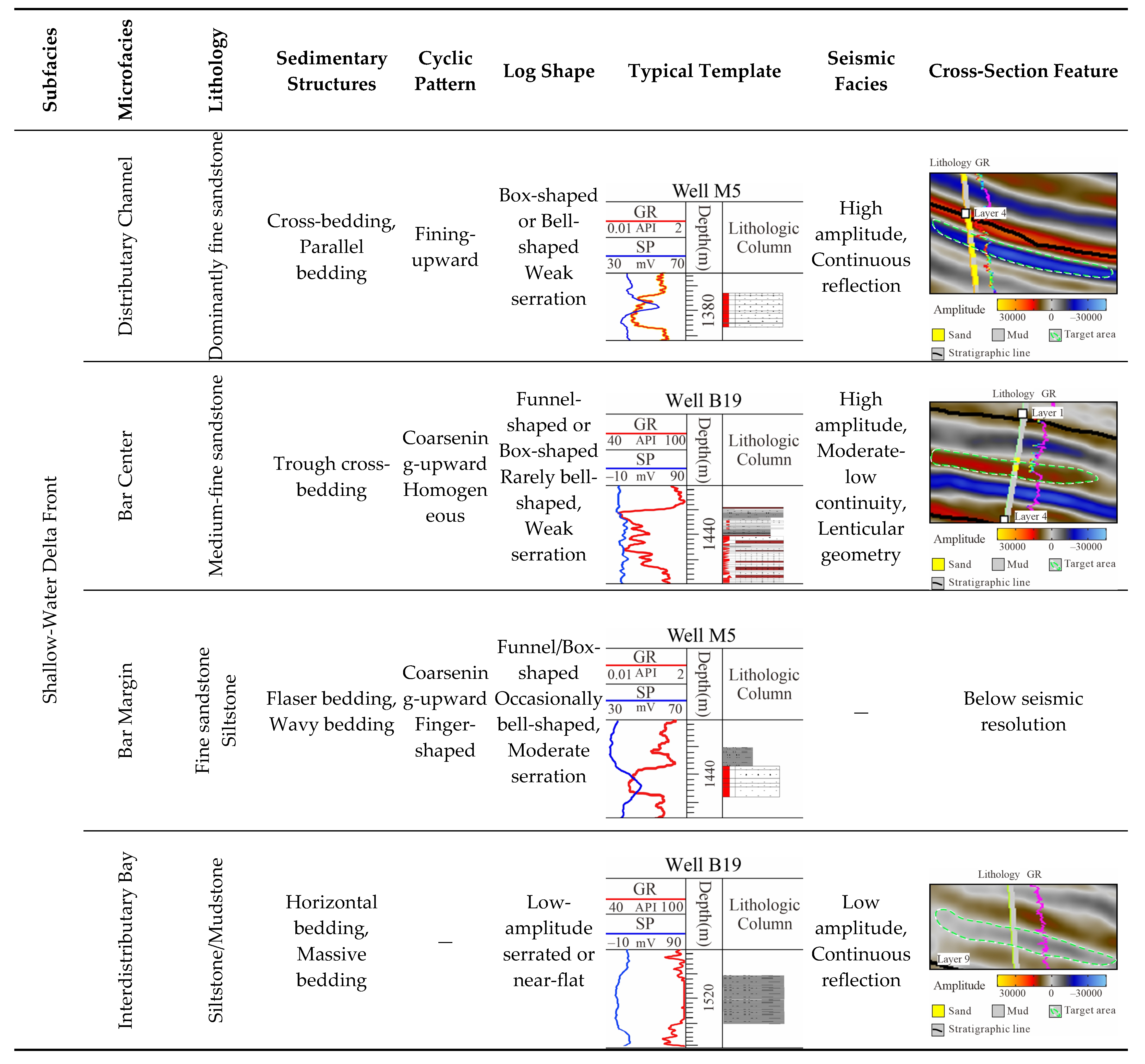
Based on systematic core observation and sedimentary context analysis, integrated with lithofacies assemblages and well-log response characteristics, three typical sedimentary microfacies have been identified in the study area, including Distributary Channels, Bar Center, Bar Margin, and Interdistributary Bay (Figure 5). These microfacies exhibit significant differences in lithological associations, grain size characteristics, and electric log curve morphologies, reflecting variations in sedimentary dynamics and depositional environments. Each microfacies type is described in detail below based on lithological features, electric log responses, and sedimentary structures.

3.2.1. Distributary Channels

Distributary channel systems, transitional between fluvial and delta plain environments, are divided into main and terminal types based on scale and depositional setting [40,41].
Main Distributary Channels consist of medium- to coarse-grained sandstones, with thicknesses up to 15 m. They exhibit large-scale (1–2 m thick) trough cross-bedding and basal scours. Well-log responses show smooth box- or bell-shaped GR curves (<60 API), with few interbeds.
Terminal Distributary Channels are composed of fine- to silt-grained sandstones, 5–10 m thick, often containing muddy interbeds and small-scale wavy cross-laminations. Their GR curves are serrated and box- or finger-shaped, ranging from 40–80 API.
Main channels act as sediment conduits in the delta front, cutting through mouth bar lobes. Terminal channels, located atop mouth bars, represent confined distributary extensions of main channels and typically exhibit a “channels overlying bars” pattern.

3.2.2. Mouth Bars

Mouth bars form at the ends of subaqueous distributary channels and exhibit high sedimentation rates [42]. Composed mainly of medium- to fine-grained, texturally mature sandstones (sorting coefficient: 1.2–1.5), they display low-angle trough cross-bedding, wavy laminations, and horizontal laminations. Sand bodies are medium to thick-bedded with coarsening-upward or homogeneous profiles. Based on hydrodynamics and lithology, mouth bars are divided into two architectural elements: bar center and bar margin [21].
Bar Center: High sand-to-shale ratio (>80%), 5–20 m thick, with excellent properties (porosity > 28%). It consists of medium-grained sandstone with high textural maturity, showing thick massive bedding and progradational coarsening-upward sequences. Well-logs show smooth funnel-to-box-shaped GR curves (40–55 API) and serrated bell-shaped resistivity curves.
Bar Margin: Sand-mud interbeds (sand-to-shale ratio: 40–60%), 3–8 m thick, with ~30% lower physical properties. Composed of fine-grained sandstone and silt with discontinuous muddy interbeds and small-scale cross-bedding. Well-log responses include funnel- or finger-shaped SP/GR curves with reversals.

3.2.3. Interdistributary Bay

Mud deposition occurs in relatively quiet waters between bar units, forming fine-grained lithologies (e.g., mudstones, silty mudstones, muddy siltstones) or interbedded deposits under low-energy conditions. These non-reservoir units act as barriers/baffles for reservoir sand bodies. In single-well facies interpretation, distinguishing their depositional origins (e.g., interchannel, interbar, or prodelta mudstones) is challenging; thus, they are collectively termed mudstone facies. They exhibit high GR values, manifested as near-baseline straight curves.

4. Methods

4.1. Reservoir Genesis and Architectural Hierarchy Classification

The study area exhibits widespread development of thick coarsening-upward sand bodies characterized by frequent muddy interbeds and complex heterogeneity. Such thick coarsening-upward delta-front deposits are relatively uncommon, with their internal muddy interfaces posing significant challenges for genetic interpretation and hierarchical classification due to limited existing research. To elucidate delta-front lobe formation and internal architecture, detailed core and laboratory analyses were conducted to define sand body characteristics. Sand body distribution was mapped through isopach analysis, while paleotopographic reconstruction confirmed a regional gentle slope setting [43]. Based on these parameters, a flume experiment was designed to replicate analogous substrate gradients, grain size distributions, and hydrodynamic conditions. This experimental approach clarifies delta-front sand body genesis and architectural hierarchy, establishing a foundation for reservoir architecture characterization. Experimental boundary conditions are detailed in Table 1.
Flume experiments revealed that Stages 61–65 constituted a continuous depositional episode where the left-positioned main channel prograded steadily, unloading sediments to form frontal bar accretionary bodies. Channel abandonment and bifurcation at Stage 66 initiated a new central channel, terminating the initial geomorphic unit (Figure 6). During Stages 66–70, the central channel sustained progradation with bar development until Stage 71 bifurcation relocated the main channel rightward, culminating in another depositional unit.
Analogizing fluvial cutoff processes, each unit defines a single mouth bar formation cycle where individual stages build front accretionary lobes. Impermeable mud layers between lobes form third-order architectural surfaces, while terminal mud drapes constitute fourth-order surfaces. Five channel–bifurcation events identified in paleogeomorphic reconstruction generated discrete mouth bars whose vertical/lateral stacking forms fifth-order mouth bar complexes.
Architectural patterns demonstrate: Lateral juxtapositions of channel–channel, channel–bar, and bar–bar units. Vertical stacking of channel–bar and bar–bar configurations. Along-dip continuous progradation with 2–3° foresets. Along-strike flat-based, convex-top geometries featuring radially accreting lobes from central zones (Figure 7). These experimental geometries provide critical analogs for subsurface reservoir characterization.

4.2. Architectural Delineation

4.2.1. Vertical Architectural Unit Division

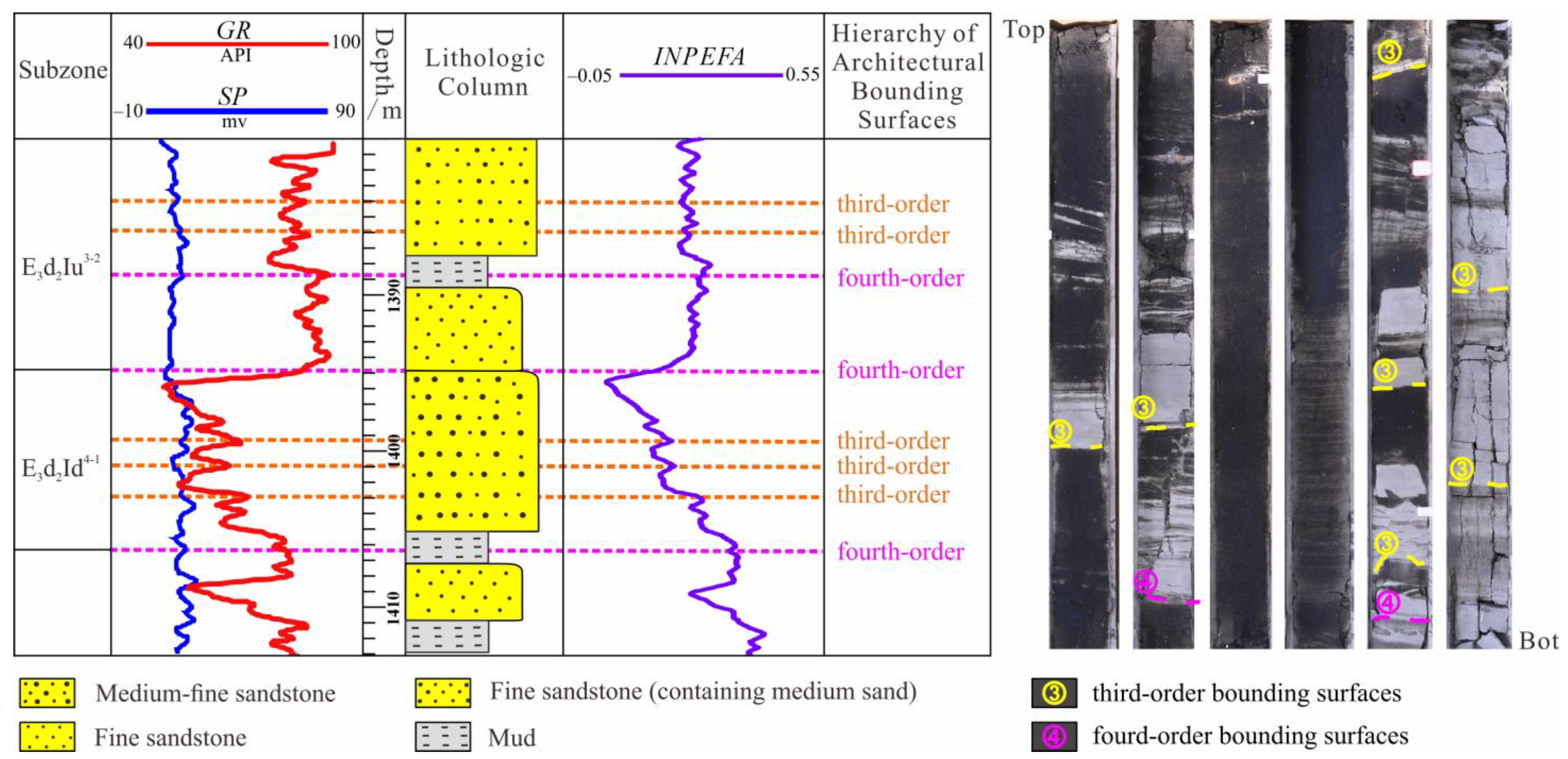
Reservoir architecture boundaries, acting as seepage barriers, are a key reason for substantial movable residual oil remaining underground. Mail’s hierarchical classification scheme for fluvial systems [36,44,45] is widely applied in real applications: architectural units are categorized as third- to fifth-order, with third- and fourth-order being the most prevalent. Third-order units are accretionary elements within sand bodies, bounded by thin muddy interbeds or changes in sedimentary structures; fourth-order units are individual channels (regarded by some as fifth-order), separated by thick mudstone drapes or erosional surfaces.
Modified from Mail [36,44,45] and based on this study’s flume experiments, our shallow-water delta terminology defines key bounding surfaces and architectural elements: mouth bars/channel deposits as fourth-order elements, and their internal accretion as 3rd-order.
In Well G19, a fourth-order mouth bar unit was identified between two boundaries: the lower at 1410.6 m, marked by silty mudstone overlying fine-grained sandstone with wavy bedding, and the upper at 1396 m, showing an abrupt contact between massive sandstone and overlying mudstone. This unit comprises four third-order elements and exhibits a coarsening-upward succession (Figure 8).

4.2.2. Planar Single-Lobe Boundary Identification

Connectivity heterogeneity among sand bodies within composite lobes significantly controls reservoir flow distribution and development performance. Based on the established geological model and validated with production data, the following markers are used to delineate individual lobe boundaries:
(1)
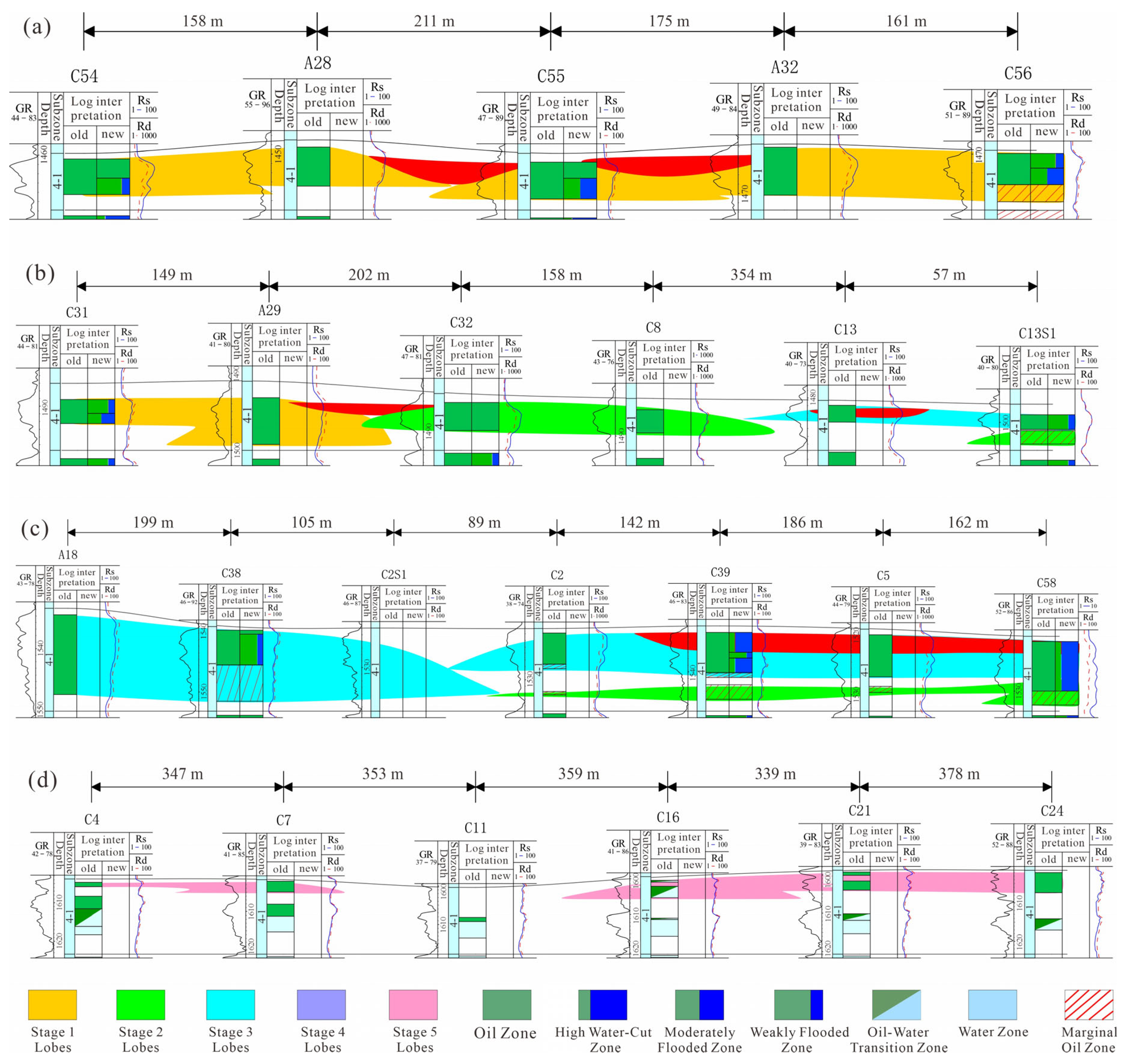
Lateral Facies Change: Lobe boundaries are marked by bar-edge sands or mudstones between bar sands, exhibiting a “thick–thin–thick” spatial pattern. For example, mudstone between wells C7 and C16 indicates a boundary near C11 (Figure 9d).
(2)
Sand body Base Elevation Difference: Consistent base elevation characterizes a single lobe. Significant elevation differences, as between wells A29 and C32 in subzone 4-1 (Figure 9b), indicate separate lobes.
(3)
Sand body Scale Difference: Pronounced thickness variations between adjacent sand bodies, such as between C2S1 and C2 (Figure 9c), suggest lobe boundaries.
(4)
Well Log Curve Morphology Difference: Contemporaneous lobes show similar log shapes. Abrupt changes, e.g., from funnel-shaped (A28) to bell-shaped (C55) logs (Figure 9a), indicate separate lobes.
(5)
Hydrocarbon Saturation Difference: Major differences in saturation or flooding characteristics between adjacent wells, like between C31 and C13S1 (Figure 9b), suggest different lobes.

4.2.3. Depositional Evolution Analysis

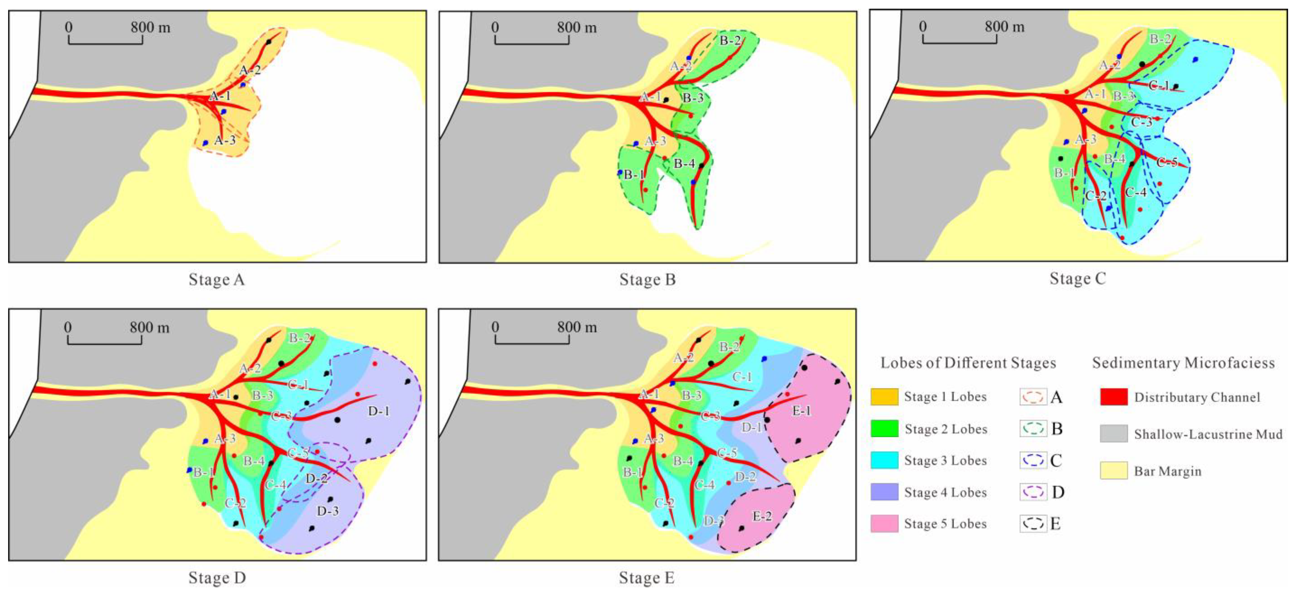
Based on a dense well pattern across the entire study area, integrated with the analysis of vertical architectural elements and lateral boundary identification methods, the distribution and evolutionary sequence of individual lobes within the composite system can be determined, revealing their depositional evolution process (Figure 10). In cross-paleoflow profile b, the lower base elevation of lobe A-3 (where letters denote depositional stages and numbers identify individual mouth bars within a stage) compared to the adjacent eastern lobe B-3 indicates that A-3 was deposited prior to B-3, while lobe C-1 exhibits the highest base elevation, signifying deposition later than both A-3 and B-3. Down-paleoflow profile B shows lobe D-2 partially downlapping onto lobes C-4 and C-5, with the frontal part of lobe B-4 subsequently downlapped by lobe C-4; lobe E-2 aggrades vertically on top of lobes D-2 and D-3. This analysis clearly establishes the temporal evolution sequence of the 14 individual lobes: Stage 1 involved the initial lake entry of the trunk distributary channel, forming lobes A-1, A-2, and A-3; Stage 2 saw migration and avulsion of the trunk channel and its branches, depositing lobes B-1 to B-5; Stages 3 and 4 featured further progradation of the trunk distributary channel and its branches towards the depositional center, forming the relatively large-scale lobes C-1 to C-5 and D-1, D-2; Stage 5 involved distributary channels forming small-scale lobes E-1 and E-2, which primarily underwent vertical aggradation on top of pre-existing lobes with only limited progradation.

4.3. Dynamic Validation

Water flooding is commonly used in secondary recovery to maintain reservoir pressure and displace oil. Its effectiveness depends on subsurface properties such as porosity, permeability, and connectivity. High permeability heterogeneity often causes injected water to channel through preferential pathways, leaving low-permeability zones poorly swept and resulting in inefficient displacement.
In the Dong-2 Member of S Field, injection profiles (Figure 11) show that Well F27 (Subzone 4-1) exhibits strong and increasing water intake, whereas adjacent Well N34 shows minimal response. Architectural analysis indicates these wells are situated in two separate mouth-bar sand bodies (A1 and A2), separated by a low-permeability barrier. This compartmentalization explains the differential flooding behavior, confirming the accuracy of the sand body delineation method and its value in assessing connectivity and guiding development.

5. Results and Discussion

Based on the preceding architectural analysis, this section systematically quantifies the dimensional characteristics and spatial distribution of the 14 identified individual lobes within the composite system. We further synthesize the architectural assemblage patterns of contemporaneously deposited lobes through quantitative characterization of hierarchical scales and stacking relationships. This approach elucidates reservoir connectivity and heterogeneity features.

5.1. Lobe Dimension

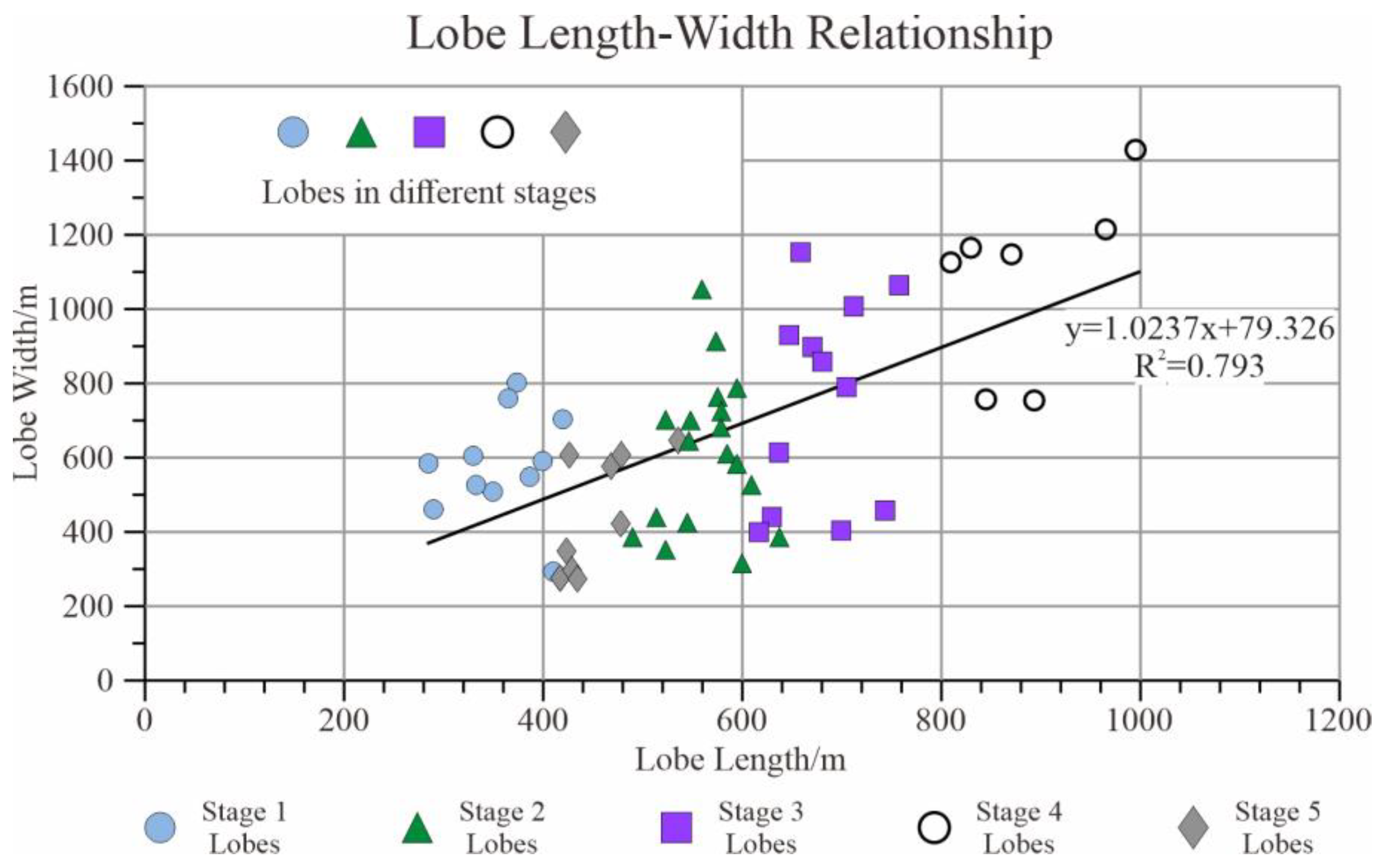
Individual lobes are measured along depositional dip (length) and perpendicular to it (width). In Subzone 4-1’s southern sector, lobes range from 385–600 m in length and 175–525 m in width. Analysis across stages shows lobe dimensions vary systematically: Stage 1 (440–760 m × 700–1500 m), Stage 2 (300–1040 m × 860–2000 m), Stage 3 (400–1000 m × 850–2300 m), Stage 4 (670–1100 m × 2000–2300 m), and Stage 5 (300–700 m × 1300–2200 m). A strong positive correlation between length and width is observed (Figure 12). Stage 1 lobes are the smallest, reflecting initial fluvial input. During Stages 2–4, lobe dimensions increase, with width peaking in Stage 4, while Stage 5 exhibits a narrowed depositional extent and smaller lobes due to increased transport distance, greater water depth, and diminished fluvial dynamics.
In the flume sedimentation experiment, the principle of geometric similarity was applied. The paleotopography was established at a horizontal scale ratio of 1:2400, where the 5-m flume length represented an actual study area extent of 12,000 m. The vertical scale ratio was set at 1:250, with an 8 cm sand layer thickness in the flume corresponding to an average unit thickness of 10 m in the study area. Simulation results demonstrate that mouth bars of different phases predominantly prograded within the delta front, exhibiting irregular, predominantly crescent-shaped geometries (Figure 6). During short depositional periods, these mouth bars displayed nearly equal length and width dimensions, characteristics that closely match the architectural analysis of actual mouth bars in the study area and indicate a good correlation.

5.2. Architectural Pattern

This study analyzes the composite lobe in Subzone 4-1 of the Dong-2 Member in S Field, Bohai Bay Basin, revealing the architecture and evolution of shallow-water delta-front lobes. A distinctive “channel-on-bar” model is established (Figure 13). Under base-level control, trunk distributary channels transport sediments basinward. At the delta front, reduced gradient and hydraulic resistance cause flow energy to dissipate, resulting in rapid deposition and the formation of multistacked mouth-bar sand bodies.
Three-dimensionally, the system exhibits a channel–lobe complex: trunk channels bifurcate into dendritic secondary channels, each hydraulically independent and controlling individual lobe distribution. Lateral migration and stacking of lobes form large composite sand bodies.
Perpendicular to flow, a “channel-over-bar” relationship is observed, with channel sands incising underlying mouth bars. Parallel to flow, lobes prograde in a compensational stacking pattern, forming tongue-shaped bodies toward the basin center.
This model offers key geological insights for predicting reservoir heterogeneity and remaining oil in shallow-water delta systems.

5.3. Comparison of Typical Shallow-Water Deltas

Deltas are sedimentary bodies formed through the interaction between rivers and seas or lakes, representing important depositional systems in transitional zones from marine to terrestrial or fluvial to lacustrine environments. Among these, shallow-water deltas are widely distributed. Influenced by factors such as accommodation space, topographic gradient, and hydrodynamic conditions, the sedimentary characteristics of shallow-water deltas vary significantly. For instance, in the Mississippi Lafourche Delta [46], distributary channels frequently bifurcate with small spacing, and mouth bar sand bodies tend to merge into thin sheet-like sand layers. In the Ordos Basin [47], the sedimentary framework is dominated by distributary channel sands, while mouth bars are relatively underdeveloped. The Niger Delta [48] features well-developed channel sand bodies, with the front characterized by contiguous lobate mouth bar sands, forming a pattern of “channels atop mouth bars”. The Mississippi Lafourche delta [49], influenced by tidal processes, exhibits higher mud content and less developed channel systems.
In the study area, the shallow-water delta deposits are predominantly sandy, with mouth bars stacking into sheet-like geometries, similar to the Niger Delta. However, the sandstone grains are relatively finer, and abundant argillaceous interbeds exist between successive mouth bar phases, ultimately forming a complex reservoir architecture.

6. Conclusions

(1)
This study establishes a depositional model for thick, sand-rich shallow-water deltas through integrated analysis of well-log, seismic, and sedimentological data, confirming mouth-bar sands as the primary reservoir units arranged in extensive lobate complexes.
(2)
Flume simulations reveal a unique delta growth mechanism where trunk distributary channels generate accretionary lobes, with subsequent channel bifurcation initiating new depositional cycles that produce vertically stacked “channel-over-bar” configurations.
(3)
The resulting three-dimensional reservoir architecture features individual lobes controlled by discrete distributary channels, while laterally amalgamated lobes from multiple channels form composite sand bodies—providing critical constraints for reservoir modeling of analogous systems.

Author Contributions

Conceptualization, L.W.; methodology, X.H. and W.F.; software, G.X.; validation, P.X. and J.L.; writing—original draft preparation, L.W. and G.X.; writing—review and editing, X.H., X.W. and Y.Y.; supervision, Y.Y.; project administration, L.W.; funding acquisition, L.W. All authors have read and agreed to the published version of the manuscript.

Funding

This study was supported by the National Nature Science Foundation of China (42372137, 42402153), and the Open Fund of Key Laboratory of Exploration Technologies for Oil and Gas Resources (Yangtze University), Ministry of Education (No. K2023-06).

Data Availability Statement

All data and materials are available on request from the corresponding author. The data are not publicly available due to ongoing research using a part of the data.

Conflicts of Interest

Jie Li was employed by the Tianjin Branch, China National Offshore Oil Corporation, Tianjin 300452, China. The remaining authors declare that the research was conducted in the absence of any commercial or financial relationships that could be construed as a potential conflict of interest.

References

  1. Hoy, R.G.; Ridgway, K.D. Sedimentology and sequence stratigraphy of fan-delta and river-delta deposystems, Pennsylvanian Minturn Formation, Colorado. AAPG Bull. 2003, 87, 1169–1191. [Google Scholar] [CrossRef]
  2. Zhang, L.; Bao, Z.D.; Lin, Y.B.; Chen, Y.; Lin, X.; Dou, L.; Kong, B. Genetic types and sedimentary model of sandbodies in a shallow-water delta: A case study of the first member of Cretaceous Yaojia Formation in Qian’an area, south of Songliao Basin, NE China. Pet. Explor. Dev. 2017, 44, 770–779. [Google Scholar] [CrossRef]
  3. Chang, J.; Chen, S.Y.; Liu, K.Y.; Yan, J.-H.; Wang, Q.; Pu, X.-G.; Yang, H.-Y. Sedimentary characteristics and evolution of shallow water delta systems of the Lower Permian Shanxi Formation in the Bohai Bay Basin region. Arab. J. Geosci. 2022, 15, 99. [Google Scholar] [CrossRef]
  4. Klausen, T.G.; Røe, S.L.; Olaussen, S. Clinoform development and topset evolution in a mud-rich delta–the Middle Triassic Kobbe Formation, Norwegian Barents Sea. Sedimentology 2018, 65, 1132–1169. [Google Scholar] [CrossRef]
  5. Li, J.; Zhang, J.; Liu, S.; Fan, Z.; Xue, H.; Sun, Z.; Yu, T. Sedimentology and sequence stratigraphy of the Paleogene lower second member of the Shahejie Formation, W79 Block, Wenliu Oilfield, Bohai Bay Basin, China. Russ. Geol. Geophys. 2016, 57, 944–957. [Google Scholar] [CrossRef]
  6. Yang, Z.; Wu, S.H.; Zhang, J.; Zhang, K.; Xu, Z. Diagenetic controls on the reservoir quality of tight reservoirs in digitate shallow-water lacustrine delta deposits: An example from the Triassic Yanchang Formation, southwestern Ordos Basin, China. Mar. Pet. Geol. 2022, 146, 105839. [Google Scholar] [CrossRef]
  7. Cai, Q.S.; Hu, M.Y.; Liu, Y.N.; Kane, O.I.; Deng, Q.J.; Hu, Z.G.; Li, H.; Ngia, N.R. Sedimentary characteristics and implications for hydrocarbon exploration in a retrograding shallow-water delta: An example from the fourth member of the Cretaceous Quantou Formation in the Sanzhao depression, Songliao Basin, NE China. Pet. Sci. 2022, 19, 929–948. [Google Scholar] [CrossRef]
  8. Zhang, L.B.; Bao, Z.D.; Dou, L.X.; Zang, D.S.; Mao, S.W.; Song, J.; Zhao, J.H.; Wang, Z.C. Sedimentary characteristics and pattern of distributary channels in shallow water deltaic red bed succession: A case from the Late Cretaceous Yaojia formation, southern Songliao Basin, NE China. J. Pet. Sci. Eng. 2018, 171, 340–356. [Google Scholar] [CrossRef]
  9. Li, X.; Xia, S.Q.; Liu, J.; Du, X.F.; Zhang, Z.Y.; Gao, L.; Wang, X.Q.; Wang, J. A case study on statistical wireline log parameters in identifying shallow-water delta microfacies of Late Dongying Formation, northern Liaozhong Depression, Bohai Bay Basin. Arab. J. Geosci. 2019, 12, 353. [Google Scholar] [CrossRef]
  10. Qin, Y.; Zhu, X.M.; Zhu, S.F.; McElroy, B. Impact of deep-time palaeoclimate on the sedimentary records and morphology of lacustrine shoal-water deltas, upper Eocene Dongying Depression, Bohai Bay basin, China. Sedimentology 2021, 68, 3253–3278. [Google Scholar] [CrossRef]
  11. Liu, Z.B.; Luo, S.S.; He, Y.B.; Yin, T.J.; Shang, F.; Lv, Q.Q.; Luo, J.X. Study on sedimentation simulation experiment of gentle-slope shallow braided river delta. J. Water Resour. Archit. Eng. 2011, 9, 9–14. [Google Scholar]
  12. Wang, Y.R.; Lin, C.S.; Zhang, Z.T.; Zhang, B.; Liu, H.Y. Sedimentary evolution and controlling factors of Early-Mid Miocene deltaic systems in the northern Pearl River mouth Basin, South China Sea. Sci. Rep. 2021, 11, 6134. [Google Scholar] [CrossRef]
  13. Zhu, X.M.; Ye, L.; Xie, S.H.; Yang, K.; Qin, Y. Sedimentary model sand case study of sand-rich shallow-water delta in continental lacustrine basins with low accommodation. J. Palaeogeogr. Chin. Ed. 2023, 25, 959–975. [Google Scholar]
  14. Zhou, D.H.; Zhang, Z.J.; Tan, H.H. Ultra-thick reservoir description technology based on spectral inversion and its application in "sand-rich" extremely shallow-water delta reservoirs in Bohai Sea area. China Offshore Oil Gas 2015, 27, 25–30. [Google Scholar]
  15. Gao, L.; Li, H.Y.; Wang, M.C.; Qin, T.; Jiang, T. Prediction of “sand-rich” fluvial reservoirs and hydrocarbon accumulation patterns in the Minghuazhen Formation, western Bohai Sea. In Proceedings of the 2017 Geophysical Technology Seminar of the Chinese Petroleum Society, Qingdao, China, 17–20 April 2017; Bohai Oil Research Institute: Tianjin, China, 2017; pp. 439–442. [Google Scholar]
  16. Ma, J.G.; Zhou, Q.; Wang, B.; Jia, H.L. Fine characterization of sandbodies in “sand-rich” fluvial sedimentary reservoirs. Geophys. Prospect. Pet. 2021, 60, 461–470. [Google Scholar]
  17. Rossi, V.M.; Ronald, J.S. The role of tidal, wave and river currents in the evolution of mixed-energy deltas: Example from the Lajas Formation (Argentina). Sedimentology 2016, 63, 824–864. [Google Scholar] [CrossRef]
  18. Valencia, A.A.; Storms, J.E.; Walstra, D.J.R. The impact of clastic syn-sedimentary compaction on fluvial-dominated delta morphodynamics. Depos. Rec. 2023, 9, 233–252. [Google Scholar] [CrossRef]
  19. Zhang, X.F.; Liu, Z.B.; Liu, C.; Tian, B.; Zhang, R. Reservoir architecture of delta front in S Oilfield, Liaodong Bay Depression and its control on remaining oil distribution. J. Northeast Pet. Univ. 2016, 40, 1–8+141. [Google Scholar]
  20. Xu, Z.H.; Wu, S.H.; Wang, Q.; Zhang, P.; Deng, M.; Feng, W.; Zhang, J.; Zhang, C. Internal architectural patterns of bar fingers within digitate shallow-water delta: Insights from the shallow core, GPR and Delft3D simulation data of the Ganjiang Delta, China. Lithosphere 2023, 2022, 9120724. [Google Scholar] [CrossRef]
  21. Li, J.F.; Wang, P.F.; Shang, B.B.; Huo, C.L.; Xu, J. Distribution of remaining oil in delta front based on reservoir architecture: A case study of Oil Group I in the Lower Member 2 of Dongying Formation in S Oilfield, Bohai Bay Basin. Fault-Block Oil Gas Field 2019, 26, 580–586. [Google Scholar]
  22. Du, X.F.; Pang, X.J.; Huang, X.B.; Wang, B.H. Characteristics of the source-to-sink system for the Paleogene Sha 2 Member of northern Liaoxi Sag, offshore Bohai Bay Basin and its control on beach bar sands. Oil Gas Geol. 2023, 44, 662–674. [Google Scholar]
  23. Qi, J.F. Two tectonic systems in the Cenozoic Bohai Bay Basin and their genetic interpretation. Geol. China 2004, 31, 15–22. [Google Scholar]
  24. Qiu, N.S.; Xu, W.; Zuo, Y.H.; Chang, J.; Liu, C.N. Meso-Cenozoic lithospheric thermal structure and thermo-rheological evolution of the Bohai Bay Basin. Earth Sci. Front. 2017, 24, 13–26. [Google Scholar]
  25. Xu, C.G.; Jiang, S.; Huan, L.; Sun, Z.Q. Sequence stratigraphy of the lacustrine rift basin in the Paleogene system of the Bohai Sea area: Architecture mode, deposition filling pattern, and response to tectonic rifting processes. Interpretation 2020, 8, SF57–SF79. [Google Scholar] [CrossRef]
  26. Guo, T.; Zhou, X.H.; Lai, W.C.; Li, J.P.; Shi, W.L. Sedimentary model and new exploration discoveries of the second member of Paleogene Dongying Formation in the middle section of Liaoxi Low Uplift. J. Chengdu Univ. Technol. Sci. Technol. Ed. 2011, 38, 619–624. [Google Scholar]
  27. Zhang, R.; Liu, Z.B.; Jia, X.F.; Wang, G.C.; Tian, B. Characterization of reservoir plane heterogeneity based on reservoir architecture research. J. Southwest Pet. Univ. Sci. Technol. Ed. 2018, 40, 15–27. [Google Scholar]
  28. Xu, Z.H.; Wu, S.H.; Yang, Q.; Yu, B. A fine characterization method for delta front reservoirs based on architectural interfaces: A case study of Paleogene Lower Dongying Formation in Suizhong Oilfield. Sci. Technol. Eng. 2016, 16, 6–13. [Google Scholar]
  29. Zhang, R.; Liu, Z.B.; Liao, X.W.; Wang, G.C.; Tian, B. Research on remaining oil distribution in delta front sandbodies during high water-cut stage. J. Southwest Pet. Univ. Sci. Technol. Ed. 2022, 44, 1–18. [Google Scholar]
  30. Patruno, S.; Hampson, G.J.; Jackson, C.A.L.; Dreyer, T. Clinoform geometry, geomorphology, facies character and stratigraphic architecture of a sand-rich subaqueous delta: Jurassic Sognefjord Formation, offshore Norway. Sedimentology 2015, 62, 350–388. [Google Scholar] [CrossRef]
  31. Soltan, R.; Mountney, N.P. Interpreting complex fluvial channel and barform architecture: Carboniferous Central Pennine Province, northern England. Sedimentology 2016, 63, 207–252. [Google Scholar] [CrossRef]
  32. Eilertsen, R.S.; Corner, G.D.; Aasheim, O.D.D.; Hansen, L. Facies characteristics and architecture related to palaeodepth of Holocene fjord–delta sediments. Sedimentology 2011, 58, 1784–1809. [Google Scholar] [CrossRef]
  33. Ocampo-Díaz, Y.Z.E.; Jenchen, U.; Guerrero-Suastegui, M. Facies and depositional systems of the Galeana Sandstone Member (Taraises Formation, Lower Cretaceous, northeastern Mexico). Rev. Mex. Cienc. Geol. 2008, 25, 438–464. [Google Scholar]
  34. Ogbe, O.B. Reservoir sandstone grain-size distributions: Implications for sequence stratigraphic and reservoir depositional modelling in Otovwe field, onshore Niger Delta Basin, Nigeria. J. Pet. Sci. Eng. 2021, 203, 108639. [Google Scholar] [CrossRef]
  35. Su, Y.S.; Wang, T.; Li, C.; Zhang, G.Y.; Zhao, Y.; Li, Y.J.; Zhao, W.; Zhao, T.Y. The sedimentary and tectonic features of the Niger Delta. Acta Petrol. Sin. 2019, 35, 1238–1256. [Google Scholar]
  36. Miall, A.D. Architectural-element analysis: A new method of facies analysis applied to fluvial deposites. Earth Sci. Rev. 1985, 22, 261–308. [Google Scholar] [CrossRef]
  37. Huang, L.; Liu, C.Y.; Zhou, X.H.; Wang, Y. The important turning points during evolution of Cenozoic basin offshore the Bohai Sea: Evidence and regional dynamics analysis. Sci. China Earth Sci. 2012, 55, 476–487. [Google Scholar] [CrossRef]
  38. Zhang, Y.; Shi, Z.; Li, J.; Wang, J.W.; Yang, B.L.; Jiang, J.G. The influence of water level changes on sand bodies at river-dominated delta fronts: The Gubei Sag, Bohai Bay Basin. Pet. Sci. 2022, 19, 58–73. [Google Scholar] [CrossRef]
  39. Zhang, J.; Gao, J.; Wu, J.; Lyu, Q.; Fang, D. Sedimentary characteristics and seismic geomorphology of the upper third member of Eocene Dongying Formation in double slope systems of Laoyemiao transverse anticline, Nanpu Sag, Bohai Bay Basin, China. Mar. Pet. Geol. 2019, 109, 36–55. [Google Scholar] [CrossRef]
  40. Olariu, C.; Bhattacharya, J.P. Terminal distributary channels and delta front architecture of river-dominated delta systems. J. Sediment. Res. 2006, 76, 212–233. [Google Scholar] [CrossRef]
  41. Zhang, L.; Bao, Z.; Dou, L.; Xu, Q. Diagenetic alterations related to sedimentary architecture of deltaic distributary channels in red beds of the Cretaceous Yaojia Formation, Songliao Basin. J. Pet. Sci. Eng. 2021, 203, 108564. [Google Scholar] [CrossRef]
  42. Valencia, A.A.; Storms, J.E.A.; Jagers, H.R.A.; van Der Vegt, H. The influence of syn-depositional compaction on clastic sediment distribution in river-dominated deltas: A modelling study. Depos. Rec. 2025, 11, 565–582. [Google Scholar] [CrossRef]
  43. Ye, L.; Zhu, X.M.; Xie, H.S.; Yang, K.; Zhang, M.Z.; Qin, W. Restoration methods of sedimentary palaeogeomorphology and applications: A case study of the First Member of Paleogene Shahejie Formation in Raoyang sag. J. Palaeogeogr. Chin. Ed. 2023, 25, 1139–1155. [Google Scholar]
  44. Miall, A.D. Facies architecture in elastic sedimentary basins. In New Perspectives in Basin Analysis; Kleinspehn, K.L., Paola, C., Eds.; Springer: New York, NY, USA, 1988; pp. 67–81. [Google Scholar]
  45. Miall, A.D. The Geology of Fluvial Deposits: Sedimentary Facies, Basin Analysis, and Petroleum Geology; Springer: Berlin/Heidelberg, Germany, 1996; p. 582. [Google Scholar]
  46. Fisk, H.N.; Kolb, C.R.; McFarlan, E.; Wilbert, L.J. Sedimentary framework of the modern Mississippi delta [Louisiana]. J. Sediment. Res. 1954, 24, 76–99. [Google Scholar] [CrossRef]
  47. Liu, Y.B.; Li, Y.H.; Zhai, W.B.; Zhao, W.X.; Li, Z.; Yang, L.H.; Guo, Y.Q. Types and genetic models of sand bodies in shallow water delta front of extremely gentle slope lake basin:A case study of Chang 81 submember of Triassic in Haotan area, Ordos Basin. Lithol. Reserv. 2025, 37, 140–152. [Google Scholar]
  48. Yin, Y.S.; Huang, S.B.; Huang, Q.Z.; Xie, P.F.; Wang, L.X.; Wu, W. Sedimentary characteristics and genesis model of the Eocene shallow-water delta front in the Koulele Oilfield, Termit Basin, Niger. Lithol. Reserv. 2025, 37, 12–25. [Google Scholar]
  49. Fitzgerald, D.M.; Kulp, M.; Penland, S.; Flocks, J.; Kindinger, J. Morphologic and stratigraphic evolution of muddy ebb-tidal deltas along a subsiding coast: Barataria Bay, Mississippi River Delta. Sedimentology 2004, 51, 1157–1178. [Google Scholar] [CrossRef]
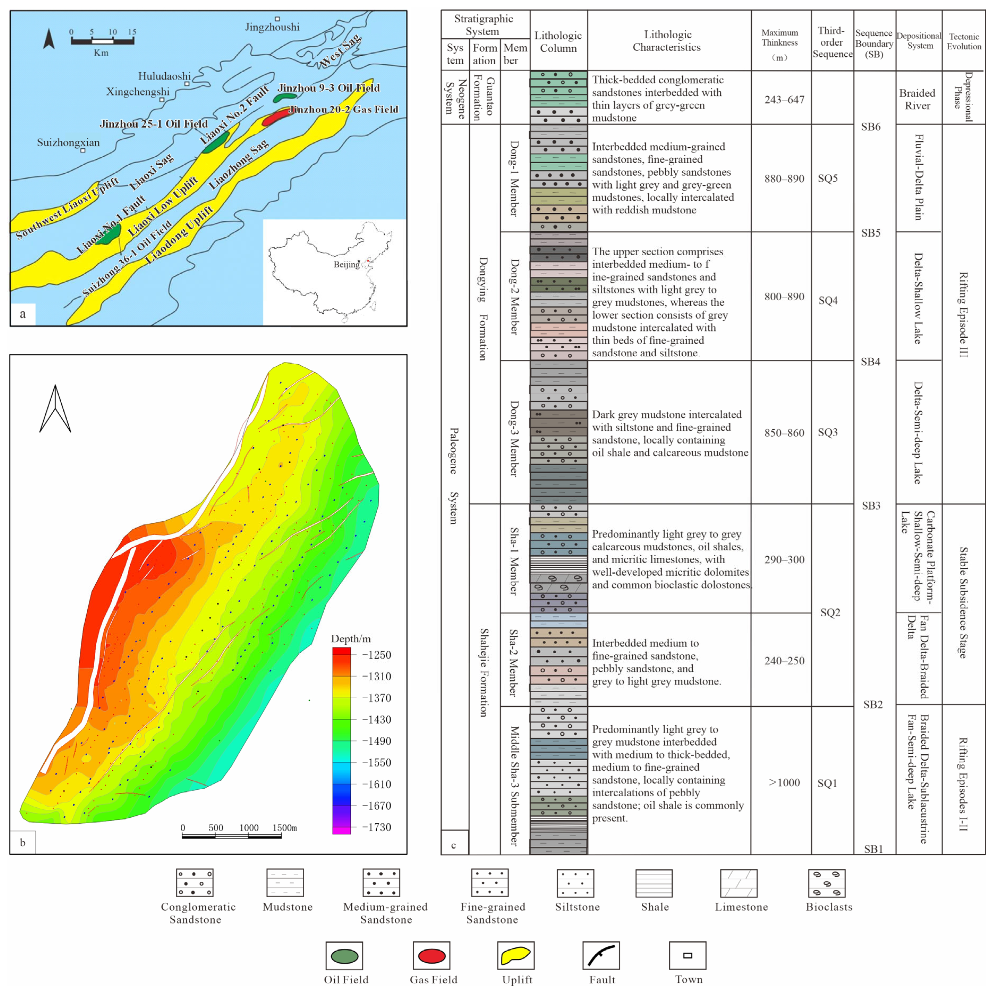
Figure 1. Tectonic location map of S Oilfield (a) [22], structure map of the top surface of the Upper I Oil Formation (b), and stratigraphic column (c).
Jmse 13 02095 g001
Figure 2. Typical rock types and sedimentary structures from cored wells of the Dongying Formation Member 2 (Ed2) in S Oilfield. (a) Trough cross-bedding, Parallel bedding, well 21, 1455.2 m; (b) Massive bedding, well M5, 1350.8 m; (c) Medium-grained Sandstone, well M5, 1357.3 m; (d) cross-bedding, well M5, 1398.46 m; (e) Lenticular bedding, Deformation structures, well M5, 1473.8 m; (f) Mudstone Band, well M5, 1456.2 m.
Jmse 13 02095 g002
Figure 3. Cross-well section of the Dongying Formation Member 2 (Ed2) in S Oilfield (Partial Wells).
Jmse 13 02095 g003
Figure 4. Seismic section across the study area of the Dongying Formation Member 2 (Ed2) in S Oilfield.
Jmse 13 02095 g004
Figure 5. Well-log interpretation template for sedimentary microfacies in the Dongying Formation Member 2 (Ed2) of S Oilfield.
Jmse 13 02095 g005
Figure 6. Analysis of the evolution and internal architecture of frontal mouth bar accretionary bodies formed during simulation periods 61–80.
Jmse 13 02095 g006
Figure 7. Dip-oriented section through the simulated deposit. (a) Planform geometry of the flume simulation; (b) Depositional stages along the LR section in the flume simulation.
Jmse 13 02095 g007
Figure 8. Characteristics of third- to fourth-order architectural surfaces within sandy-muddy bodies of the mouth bar.
Jmse 13 02095 g008
Figure 9. Identification criteria for single lobe boundaries. (a) Well log curve morphology difference; (b) Sand body base elevation difference and hydrocarbon saturation difference; (c) Sand body scale difference; (d) Lateral facies change.
Jmse 13 02095 g009
Figure 10. Evolutionary stages and depositional processes of the single lobe in the southern part of Layer 4-1, S Oilfield.
Jmse 13 02095 g010
Figure 11. Water injection profile of Well F27, fluid production profile of Well N34, and well locations.
Jmse 13 02095 g011
Figure 12. Dimensions and length-to-width ratio of single lobes in Layer 4-1 of the Dongying Formation Member 2 (Ed2), S Oilfield.
Jmse 13 02095 g012
Figure 13. Architectural model for shallow-water delta deposits in the Dongying Formation Member 2 (Ed2) of S Oilfield, Bohai Bay Basin.
Jmse 13 02095 g013
Table 1. Boundary conditions for sand-rich deltaic sedimentary simulation.
ParameterS Oilfield (Prototype)Flume Experiment (Model)
Substrate SlopeGentle slope zone: avg. 0.08°
Slope-break zone: 1.37°
Avg. 0.2°
Water–Sediment ConditionsHigh sediment supply (coarse-grained), strong hydrodynamicsWater discharge: 500 mL/s
Sediment supply: 2 g/s
Sediment CompositionSand-dominated (medium-fine sand >60%)Medium-fine sand: D50 = 200 μm quartz
Silt: D50 = 70 μm quartz
Clay: Montmorillonite powder
Water LevelShort-term base-level fall during rapid progradationStep 1–40: 10 cm (stable)
Step 41–70: 9 cm (−1 cm)
Step 71–100: 8 cm (−1 cm)
Step 101–117: 5 cm (−3 cm)
Monitoring-Terrestrial Laser Scanning (TLS) every 30 min, Time-lapse photography (1-s interval)
Disclaimer/Publisher’s Note: The statements, opinions and data contained in all publications are solely those of the individual author(s) and contributor(s) and not of MDPI and/or the editor(s). MDPI and/or the editor(s) disclaim responsibility for any injury to people or property resulting from any ideas, methods, instructions or products referred to in the content.