Abstract
In this paper, the nonlinear bending of the slender flexible cable connected to floating offshore energy platforms is considered. The aim is to find accurate values for the bending stress in the catenaries that lead to fatigue and short lifetime. A new approach called Extended Stiffened Catenary Theory (ESCT) is described and outlined, which accurately predicts the bending stresses such that they can be validated by high-fidelity FEM software, e.g., ABAQUS 2024. It is found that some widely used software, such as Orcaflex 11.4, underestimates these bending stresses. Although the Orcaflex uses built-in FEM software to analyse the stresses, there are substantial differences between the results. Since the stresses are underestimated, it can lead to a wrongly estimated higher fatigue lifetime. Therefore, a critical review of stress analysis in Orcaflex is carried out to find the origins of such underestimation. It is shown that the explicit integration of equations of motion in Orcaflex is the reason for such underestimation, even in static analysis. The ABAQUS can predict accurately because of implicit (standard) integration. It is concluded that using this ESCT allows us to estimate a more realistic and reliable stress, thereby leading to a realistic lifetime for catenary umbilicals and cables for floating platforms.
1. Introduction
Floating offshore platforms are emerging technologies and could be installed at sea depths above 100 m, where the capacity factors of such turbines and also hydrocarbon resources increase substantially [1]. The dynamic power cables and umbilicals for transmitting electrical energy and signals also float with the platform that faces wind and sea waves. The induced motion applied to the cables results in subsequent sag and hog bending across the length of the cable. The higher amplitude of such fluctuating bending stress reduces the fatigue lifetime substantially. Unlike the moorings in the platform, these cables are more prone to fatigue, and their bending behaviour could be analysed in more detail due to their high bending stiffness. Recent research on the bending behaviour of such cables uses linear bending theories [2] that are appropriate for low-curvature configurations only.
Bending stress is a key factor impacting fatigue, performance, and safety in subsea structural systems, including risers, cables, and umbilicals. In flexible risers with complex, multi-layered assemblies, and also cables and umbilicals, the bending behaviour departs from linear assumptions and improved nonlinear analytical models are needed to capture curvature and strain accurately [3].
The reliability of many other components, like wellhead connectors, is also related to bending stress resulting from the wave-induced vibration bows. This makes bending stress and fatigue-life assessment under different types of loading essential [4]. Moreover, environmental loads, such as ocean currents and waves, impose additional bending moments, which in deepwater drilling risers notably influences stress distribution and overall mechanical response under dynamic loading [5].
The examination of the dynamic response models has shown a significant amplification in bending strain in deepwater risers [6] under combined axial loading. This can accentuate bending fatigue risk in the presence of the vortex-induced vibrations, which always exist in these systems [7]. Integrated fatigue analyses of connected systems like drilling riser–BOP–well casing assemblies reveal that the bending stress transfer can produce fatigue hotspots, particularly when joint geometries and load paths are complex [8]. Experimental methods such as resonant bending fatigue rigs also validate that bending stress magnitudes vary significantly with section geometry and support conditions [9], thereby increasing the fatigue risk in relevant hotspots.
For bending stress estimation in the wave-induced fatigue of steel risers, augmented predictive capability is used, via training the models using a neural network [10]. In specialised configurations like lazy-wave hydrogen production risers, severe bending stress occurs in the touchdown zone where seabed interaction is present. Therefore, accurate bending stress estimation should be captured by appropriate models [11].
In the offshore renewable sector, to monitor the health of TLP-FOWTs (floating offshore wind turbines), sensors are deployed on tendons to measure bending strains in real-time that reflect both operational loads and environmental conditions [12], since there is a direct relationship between bending strain and health. In unbonded flexible risers under cyclic loading conditions, with complex shape, material, contact behaviour, and strong nonlinearity, bending stress estimation requires high-fidelity FEM analysis [13].
Together, these studies show that precise bending stress determination is indispensable in the safe design, life prediction, and reliability of subsea structural elements.
In this paper, a new stiffened catenary theory is formulated that can replace the natural catenary assumption. The natural catenary theory is used in moorings and other slender objects with negligible bending stiffness. It is shown that an extended nonlinear bending theory is required and is governed by highly nonlinear ODE [14]. Since the layback and final deformed shape are closely coupled, an accurate solution should be obtained via an iterative algorithm.
The results presented in this paper show an accountable and reliable prediction of the bending stress that is validated by high-fidelity FEM software (ABAQUS standard implicit). We also analyse the bending stress using a well-known software that is frequently used in the offshore industry named Orcaflex, which uses an explicit FEM beam model.
Those results are not promising and indicate bending stresses that are underestimated substantially. This can lead to an overestimated fatigue lifetime that is not realistic and reliable.
We recommend that this new theory (ESCT) should be employed in commercial software to model and analyse floating offshore structures and wind turbine platforms. This can lead to a realistic and reliable fatigue lifetime computed by the software. A necessary prelude to achieving this objective is the development of an AI-based surrogate model for this new theory in future applications.
This paper consists of eight sections and starts with the Introduction in Section 1. This is followed by Section 2, which describes the Extended Stiffened Catenary Theory (ESCT), which considers the effect of bending stiffness on the suspended catenary shape. In Section 3, the Natural Catenary Theory (CTN) is described, which ignores the bending stiffness. In Section 4, the stiffness and mass matrices in two high-fidelity FEM software are expressed in a style to be compared with each other. In Section 5, the implicit integration in ABAQUS and explicit integration in Orcaflex are described in a style to be compared with each other. In the short Section 6, the bending stress resulting from ESCT and NCT is compared, a significant difference in bending stress is shown. This leads to Section 7, in which the validity of ESCT and NCT is tested via FEM software in both ABAQUS and Orcaflex 11.4. In conclusion, Section 8 describes why ABAQUS 2024 can validate ESCT, whereas Orcaflex 11.4 results are close to NCT, and the disadvantages of the latter is discussed.
2. Extended Siffened Catenary Theory
The Extended Stiffened Catenary Theory (ESCT) is an updated approach that considers the effect of bending stiffness on the determination of the bending stress in a catenary-shaped flexible structure. The theory was initially developed in [15], in which the nonlinear bending equations were solved using an approximate series solution. In the extended version of that theory, the governing nonlinear equations are solved by an iterative optimisation method that is described in this section.
Governing Equations
Figure 1 shows the schematic diagram of a flexible slender cable attached to a floating platform. If the bending stiffness is negligible, the suspended cable with length s can be expressed as a natural catenary geometry.
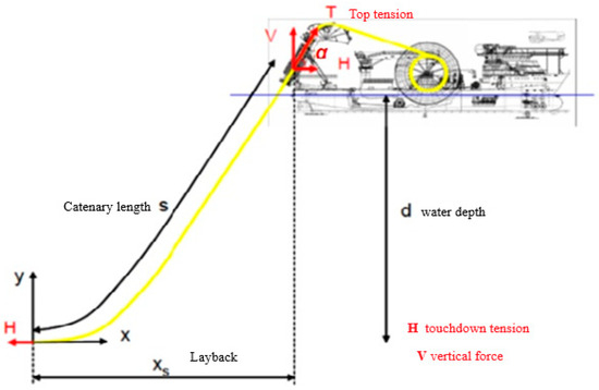
Figure 1.
Suspended catenary cable or umbilical.
However, in floating platforms, the power cables and umbilical have considerable bending stiffness, and the natural catenary assumption is not valid. In order to study the stiffened catenary geometry, the free-body diagram of a differential length of the suspended cable, presented in Figure 1, is shown in Figure 2.
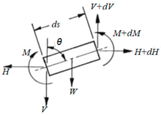
Figure 2.
Free-body diagram of a cable segment.
In this study, the sea depth is d, and the weight per unit length of the submerged cable is W. Additionally, the touchdown tension in the cable is H, and the following dimensionless parameters are defined as follows:
In the above parameters, T is the top tension (see Figure 1), the equivalent modulus of elasticity of cable material is E, and the second moment of the cross-section of the cable is I.
In ESCT, herein is the extended version of the approach used by [4]. In fact, the length of the suspended cable is unknown (unlike Dixon in [15]). Therefore, we must introduce the guessed length Lg to set up the governing equation. Thereafter, a dimensionless parameter z represents the coordinate s across the pipe (see Figure 1).
In [14], it is shown that the dimensionless governing equation is
with boundary conditions as follows:
In the first guess, the resulting length Lr will be as follows:
This means that the guessed length of Lg is just an initial estimation. Therefore, an iterative procedure should be implemented to change and solve the nonlinear ODE again. After a substantial number of iterations that can be conducted via an intelligent optimisation method, we can reach the following situation:
The following final nonlinear ODE will be solved at the end of the iterative process:
Thereafter, from versus z in the final ODE and using
the bending moments in each cross-section can be found. This gives the maximum bending stress that will occur during platform operation
in which D is the external diameter of the cable core.
The flow chart in Figure 3 clearly shows the computational steps in ESCT.
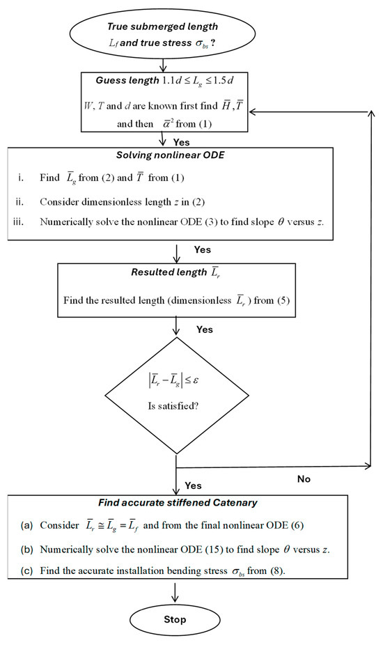
Figure 3.
Computational steps in ESCT.
3. Natural Catenary Theory (NCT)
In NCT, the bending stress is found using a simplified model that assumes the natural catenary shape, in which the bending stiffness related to E I is negligible. This may be valid for moorings or chains [16], and also for the case where d (depth) is very high, such that Equation (6) will change to:
where Lc is the natural catenary length, which can be expressed in terms of the top cable angle and laying angle (shown in Figure 1).
Then, the radius of curvature formula is applied to the natural catenary in y above. This assumes a bending radius at any cross-section of the suspended cable (see Figure 1), which can be found by substituting y(x) into the curvature formula [5], which results in the following:
Through the above assumption, the bending stress at any cross-section can be found from the outer diameter of the suspended cable core, as follows:
4. Finite Element Method in ABAQUS and Orcaflex
In FEM, the long continuous catenary cables and umbilical are discretized into several short elements. If we consider each element with two nodes, 1 and 2 only, we will face 12 Degrees of Freedom (DOF) in local coordinates x, y and z. The six translational DOF are as follows:
Moreover, the six rotational DOF are as follows:
Correspondingly, the applied forces in nodes 1 and 2 are as follows:
Moreover, the applied moments in nodes 1 and 2 are as follows:
In static analysis, the force-moment vector (12 × 1) is related to the displacement–rotation vector (12 × 1) via a stiffness matrix (12 × 12), as follows:
The stiffness matrix above consists of 16 submatrices. All these submatrices are (3 × 3) and include the parameters of A (beam cross-sectional area), L (beam length), Ix and Iy (2nd area moment about x and y axis), E (Young Modulus), G (shear modulus), and J (Polar 2nd area moment). The stiffness between the and also and is as follows:
The stiffness between the and also and is
The stiffness between the and also and is
The stiffness between the and also and is
The stiffness between the and also and is
The stiffness between the and also and is
The stiffness between the and also and is
The stiffness between the and also and is
The ABAQUS B31 (linear beam) [17] and Orcaflex line elements [18] (based on Euler–Bernoulli beam theory), therefore, share the above stiffness expressions, but the ABAQUS can switch between Euler–Bernoulli (no shear) and Timoshenko (shear included). Orcaflex, by default, uses Euler–Bernoulli only (unless you enable shear flexibility explicitly in certain contexts). In this article, we compare the results based on the Euler–Bernoulli theory. Both ABAQUS and Orcaflex software perform static analysis via the dynamic relaxation method, which requires the stiffness matrix and the mass matrix.
Implicit ABAQUS often uses dynamic relaxation to obtain static equilibrium before continuing with dynamics. The idea is to apply static loads gradually, then let the structure “vibrate” with artificial mass and damping until the kinetic energy dissipates. A numerical damping parameter is introduced to remove oscillations and accelerate convergence. Once velocities and accelerations vanish, the system is effectively in static equilibrium, and results are written as the static solution.
The Orcaflex has no “direct static solver” in the strict sense. Instead, it relies on dynamic relaxation to generate an initial equilibrium configuration. The line (cable/umbilical/pipe) is placed in the environment, then a transient dynamic simulation is run with artificial damping.
Once the motion decays below a tolerance, the configuration is saved as the static starting point for subsequent analyses.
To introduce the mass matrix for dynamic relaxation, we define the six translational accelerations of the nodes 1 and 2, which are as follows:
Moreover, the six angular accelerations of the nodes 1 and 2 are as follows:
For dynamic analysis, Equation (14) changes into:
The mass matrix between the and also and is
The mass matrix between the and also and is
The mass matrix between the and also and is
The mass matrix between the and also and is
The mass matrix between the and also and is
The mass matrix between the and also and is
The mass matrix between the and also and is
The mass matrix between the and also and is
The above formulas for the elements of the mass matrix are used in ABAQUS standard (implicit integration), in which the off-diagonal elements of the mass matrix play a significant role when a static analysis is performed via dynamic relaxation. The integration procedure will be shown in the subsequent section.
However, the mass matrix that is used in Orcaflex [18] is completely different and, according to Figure 4, is based on the lumped masses that are connected to the coupling springs.
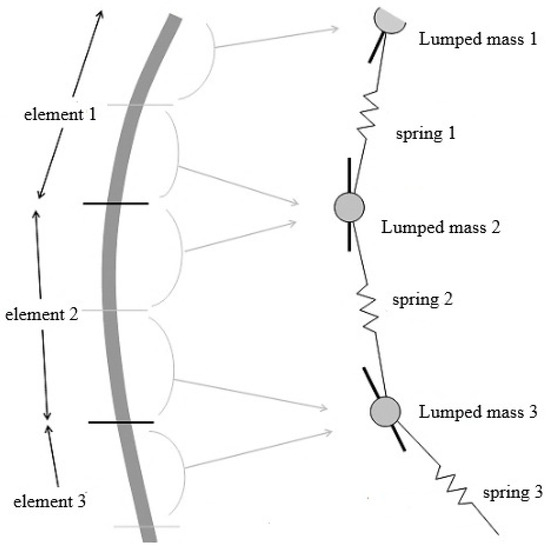
Figure 4.
Line modelling in Orcaflex FEM.
The elements of the mass matrix in Orcaflex are as follows:
While the ABAQUS mass matrix formulation uses the “Bending-Shape Inertia” concept, in Orcaflex the “Section Spin Inertia” concept is used, which can provide stability in explicit integration [18], which is described in the next section.
5. Implicit and Explicit FEM in Solving a Static Problem
Any static FEM problem can finally be formulated as follows:
In (17), the matrix is the overall global stiffness matrix, is the external force–moment vector, and is the resulting displacement–slope vector of the nodes.
When the system is strongly nonlinear in geometry (like a catenary pipe), FEM software, like ABAQUS and also Orcaflex, converts the static problem into a dynamic problem and Equation (17) changes to
In (18), is the fictitious mass matrix and is the fictitious damping matrix. is a linear–angular velocity vector and is the linear–angular acceleration vector of all nodes.
To start, we need the initial condition , , and at t = 0. Then, according to Newmark, the nodal velocity vector will be as follows:
In (19), the and are Newmark parameters, and the time step number is n. Followed by velocities, the acceleration vector can be found as follows:
In (19) and (20), is the fictitious step time. In explicit FEM, the stiffness matrix in Equation (17) will be updated to
whereas the external force vector will be converted to an effective external force vector as follows:
Constructing (22) is possible, since the displacement, velocity, and acceleration vectors in the previous step are known from (19) and (20). Therefore, the fundamental Equation (17) will change into the following form:
Solving Equation (23) requires the inversion of the updated stiffness matrix . Therefore, the computational procedure is time-consuming, and there may be a convergence problem in some nodal degrees of freedom. However, by overcoming the convergence, the method is accurate and can be applied to complex static and dynamic problems. In ABAQUS, the implicit version of the software is called ABAQUS standard.
The explicit version of ABAQUS and also FEM in Orcaflex is based on the central difference method (not Newmark). This method is also based on Equation (18) and , the fictitious mass matrix, and , the fictitious damping matrix. However, the velocity and acceleration vectors are obtained using the following:
Equations (24) and (25) enable Equation (18) to be converted into the following form:
In explicit FEM, we neglect the fictitious damping matrix, i.e., , and the fictitious mass matrix is diagonal, and if the system comprises N nodes, the form of the mass matrix will be
whereas the stiffness matrix is non-diagonal, and a column vector may be a fully non-zero as follows:
Since the damping matrix can be neglected, the matrix Equation (26) can be converted to the following nodal equation:
Therefore, matrix inversion is not required. The computational time is very low, and the convergence problem does not exist. Almost all complicated static and dynamic problems can be solved by the explicit version. However, the accuracy of the results cannot be guaranteed. The explicit version of ABAQUS is suitable for extreme loading and impact events. The explicit FEM in Orcaflex also performs static analysis without using the inversion of the stiffness matrices. The adjusting parameter in (29) is the time step that should be carefully adjusted by considering the following expressions:
In (30), is a safety factor, is the critical step time, and is the highest natural frequency of the discretised system. The procedure for calculating and regulating the above parameters is not available in the public domain. Regardless of the elegance of the time step adjustment, the results via Orcaflex explicit FEM cannot be as accurate as implicit (standard) FEM in ABAQUS.
Equations (22) and (23), together with accurate (non-diagonal) mass matrices in (15), are used in implicit integration and can provide accurate results and bending stress in ABAQUS standard. However, Orcaflex implements Equation (29), via a diagonal mass matrix (27) that originates from the mass matrix (16). This makes the integration much easier (explicit) and does not require matrix inversion, but the outcome provides inaccurate results.
Further disadvantage in explicit integration (Orcaflex) is the time step adjustment in (30), safety factor, and , which is the critical step time, and (highest natural frequency), since they are not available to users. They are predetermined by developers. Therefore, they cannot provide accurate results, including bending stress that is dependent on angular displacement.
6. Testing ESCT Versus NCT in a Numerical Example
A stiff slender example herein is a pipe with diameter D = 323.9 mm and thickness ts = 15.9 mm that is made from steel with a density 7850 Kg/m3 and a yield stress σY = 448 MPa. It will be held by a platform with the sea depth d = 300 m, and the top holding tension T = 1.6 Wd; the bending stress computed from NCT and ESCT is shown in Table 1.

Table 1.
Comparing two types of bending stresses.
As can be seen in Table 1, there are substantial differences in bending stresses obtained via NCT and ESCT, particularly in shallow water like 300 m depth. Floating platforms are usually installed at depths above 100 m, and the bending stress differences in such depths (less than 300 m) are even greater.
Since the fluctuating bending stress is the main source of fatigue, its accurate estimation will be a necessary prelude in fatigue lifetime determination. Therefore, the existing high-fidelity FEM software is required to verify if NCT or ESCT is accurate enough.
7. Accuracy Verification via ABAQUS 2024 and Orcaflex 11.4
The ABAQUS, which is a commercially available FEM software [6], is used to model the suspended pipe in the previous example. The PIPE21 beam element is used to model the suspended pipe via 300 elements. Due to the strong nonlinear geometry of the suspended pipe, convergence warning messages are present in the data file. The stress maps of the ABAQUS standard (implicit) are shown in Figure 5. It shows that results for the von Mises stress are reasonably close to the stiffened catenary (ESCT), and predicts plastic deformation exactly like the stiffened catenary theory.
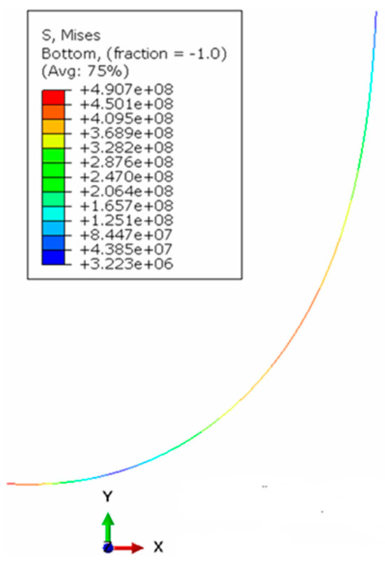
Figure 5.
von Mises stress map of ABAQUS standard.
The ABAQUS results are only for comparison purposes. The initial position of the nodes is based on the natural catenary expression. They are generated by MATLAB 2024b, then exported to ABAQUS. Upon loading (the top tension weight), the nodes move to the loaded positions. These new positions of the nodes form the stiffened catenary shape in ABAQUS. Although there is not much difference in the shape and length of stiffened and natural catenaries, the resulting stresses are substantially different and close to ESCT.
Similar analysis is performed for the suspended pipe by using Orcaflex 11.4 software [18] as shown in Figure 6. The suspended pipe (400 m long) in the previous example is modelled by 400 beam elements of pipe type. The boundary conditions in both ABAQUS and Orcaflex are set to be consistent with both NCT and ESCT, since the objective is to study the bending stresses only.
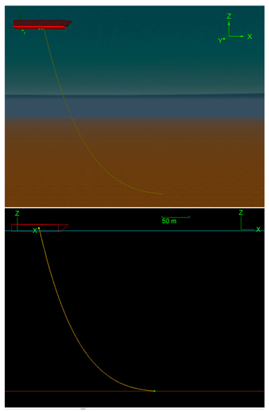
Figure 6.
Suspended pipe model in Orcaflex.
Orcaflex also uses a finite element model for simulating lines, specifically using a lumped mass model (see Figure 3). This approach models the line as a series of discrete segments, each treated as a beam element, to accurately capture the dynamic behaviour of the lines under various loading conditions.
Since the beam element in Orcaflex is designated by a lumped mass and a spring [18], we cannot expect the same result as using PIPE21 in ABAQUS, and the results will be different. However, the Orcaflex is frequently used in the offshore industry, including in floating wind turbines, and if it results in inaccurate bending stress, it leads to incorrect fatigue lifetime predictions.
As shown in Table 2, the bending stress predicted via Orcaflex is much lower than that obtained via ABAQUS, and is closer to the result from NCT. The subsequent outcome of this is an overestimation of the fatigue lifetime. The values of other stresses, like hydrostatic and tensile, are significant only in deep water. This will happen for oil and gas platforms, but in wind energy platforms, the maximum depth is not above 300 m.

Table 2.
Comparing four types of bending stresses.
It should be remembered that NCT and Orcaflex always underestimate bending stresses. To verify that, substantial simulations are performed to determine the required correction factor. This correction factor provides the ratio of the ESCT bending stress to the NCT bending stress and is given by
This enables the theory of NCT to be used together with this correction factor, for accurate estimation of the bending stress. This correction factor is always , as shown in Figure 7, which indicates the correction factor versus the bending stiffness parameter and the top tension parameter. The figure shows that when the bending stiffness parameter increases (it occurs at low depth), the correction factor is higher.
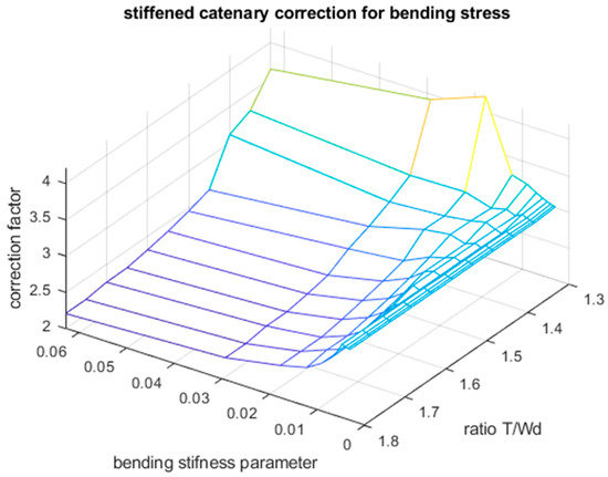
Figure 7.
Bending stress correction factor
The weight per unit length of the pipe W appears in many formulas and can be found from the following:
where and are densities of the steel pipe and insulator, whereas and are cross-sectional areas of the steel and insulator in the pipe, and ti is the insulator thickness. The hydrostatic stress at the pipe cross-section depends on the ts or the thickness of the steel pipe and is given by the following:
The hydrostatic pressure P depends on the water column height and density above the local cross-section of the pipe, and is given by the following:
Apart from bending and hydrostatic stresses, and tension in each cross-section, the axial stress exists as well. A compressive force resulting from pressure on the exposed end at the touchdown point appears to affect the value of the axial stress. The final form of is
The effective von Mises stress can be defined according to the following formula:
In the above formula, bending stress is easily calculated via the assumption that the suspended pipe has a natural catenary shape. However, if bending stress is formidably calculated via ESCT, it is calculated from the following formula:
Therefore, Table 3 can be produced, in which the maximum von Mises stress can be found using NCT, ESCT, ABAQUS, and Orcaflex. Since the axial and hydrostatic stresses are low compared to the bending stress, the values in Table 2 and Table 3 are close to each other, indicating the dominance of the bending stress.

Table 3.
Comparing four types of Mises stresses.
8. Conclusions
In this article, the fluctuating stresses in the flexible slender structures of floating platforms are investigated via a new method called ECST. The results of this new method are verified by high-fidelity ABAQUS standard software with implicit integration. It is shown that Orcaflex software with explicit integration underestimates these stresses significantly and cannot be suitable for fatigue lifetime determination. Through expressing detailed governing equations in two FEM software, we have shown that the mass matrix in Orcaflex is based on Section Spin Inertia (diagonal) and this, together with explicit integration, leads to inaccurate static analysis. The ABAQUS, on the other hand, not only performs implicit integration but also uses a consistent mass matrix (non-diagonal) considering bending deformation. This enables the estimation of an accurate bending stress. Since the ESCT is validated via high-fidelity FEM, it is recommended that a surrogate database of this new theory be used to provide correction factors for NCT in the future.
Funding
This research received no external funding.
Data Availability Statement
The raw data supporting the conclusions of the article will be made available by the author on request.
Conflicts of Interest
The author declares no conflict of interest.
Abbreviations
| d | Laying depth |
| Dimensionless depth parameter | |
| D | Outer diameter of steel pipe |
| Modulus of elasticity | |
| g | Gravity acceleration |
| H | Touchdown tension |
| Second moment of cross-section (in bending) | |
| Guessed length and final length of suspended pipe. | |
| Dimensionless guessed and final and resulted lengths. | |
| Natural catenary length of suspended pipe | |
| Bending moment in pipe cross-section | |
| P | Hydrostatic pressure |
| Bending radius of natural catenary | |
| s | Coordinate of cross-section of the suspended pipe |
| The top tension that holds the suspended pipe | |
| Top tension ratio | |
| V | Shear force in pipe cross-section |
| Submerged weight of the pipe per unit length | |
| Horizontal and vertical coordinate for suspended pipe | |
| Layback distance | |
| z | Dimensionless coordinate for s |
| Laying angle | |
| Bending stiffness parameter | |
| Fractional powers at empirical formula (34) | |
| Complementary slope angle | |
| , | Natural and stiffened catenary bending stresses. |
| , | Axial and hydrostatic stresses |
| , | Natural and stiffened catenary von Mises stresses |
| Yield strength of the steel pipe | |
| Correction factor | |
| Densities of steel, insulation, and seawater |
References
- Cruz, J.; Attcheson, M. Floating Offshore Wind Energy: The Next Generation of Wind Energy (Green Energy and Technology), 1st ed.; Springer: Cham, Switzerland, 2016. [Google Scholar]
- Okpokparoro, S.; Sriramula, S. Reliability analysis of floating wind turbine dynamic cables under realistic environmental loads. Ocean Eng. 2023, 278, 114594. [Google Scholar] [CrossRef]
- Yuna, R.H.; Jangb, B.S.; Kima, J.D. Improvement of the bending behavior of a flexible riser: Part I—nonlinear bending behavior considering the shear deformation of polymer layers. Appl. Ocean Res. 2020, 101, 102204. [Google Scholar] [CrossRef]
- Li, Z.; Luo, W.; Wang, Y.; Wang, M.; Li, Y.; Hu, Y.; Wang, Y. A method for the fatigue-life assessment of subsea wellhead connectors considering riser wave-induced vibration. Ocean Eng. 2024, 306, 118044. [Google Scholar] [CrossRef]
- Tang, L.; Huang, Z.; Zhu, X.; Zhou, Y.; Li, B. Investigation of the mechanical response of a deep-water drilling riser to ocean currents and waves. Adv. Mech. Eng. 2019, 11, 1–11. [Google Scholar] [CrossRef]
- Lei, S.; Zheng, X.Y.; Kennedy, D. Dynamic response of a deepwater riser subjected to combined axial and transverse excitation by the nonlinear coupled model. Int. J. Non-Linear Mech. 2017, 97, 68–77. [Google Scholar] [CrossRef]
- Wu, J.; Yin, D.; Lie, H.; Larsen, C.M.; Baarholm, R.J.; Liapis, S. On the Significance of the Higher-Order Stress in Riser Vortex-Induced Vibrations Responses. J. Offshore Mech. Arct. Eng. 2019, 141, 011705. [Google Scholar] [CrossRef]
- Guimaraes, F. Dynamics of the System Drilling Riser–BOP–Well Casing—Wellhead Casing Fatigue Analysis. J. Offshore Mech. Arct. Eng. 2024, 146, 021401. [Google Scholar] [CrossRef]
- Wittenberghe, J.V.; De Baets, P.; De Waele, W.; Ost, W.; Verstraete, M.; Hertele, S. Resonant Bending Fatigue Test Setup for Pipes With Optical Displacement Measuring System. J. Offshore Mech. Arct. Eng. 2012, 134, 031702. [Google Scholar] [CrossRef]
- Cortina, J.P.R.; de Sousa, F.J.M.; Sagrilo, L.V.S. Neural Networks Applied to the Wave-Induced Fatigue Analysis of Steel Risers. Math. Probl. Eng. 2018, 2018, 2719682. [Google Scholar] [CrossRef]
- Hajitaheriha, M.M.; Shiri, H. Analytical Modeling of the Lazy-Wave Hydrogen Production Riser (HPR) with Incorporation of Seabed Interaction in the Touchdown Zone. J. Mar. Sci. Eng. 2024, 12, 2129. [Google Scholar] [CrossRef]
- Chung, W.C.; Pestana, G.R.; Kim, M.H. Structural health monitoring for TLP-FOWT (floating offshore wind turbine) tendon using sensors. Appl. Ocean Res. 2021, 113, 102740. [Google Scholar] [CrossRef]
- Tan, Z.; Quiggin, P.; Sheldrake, T. Time Domain Simulation of the 3D Bending Hysteresis Behavior of an Unbonded Flexible Riser. J. Offshore Mech. Arct. Eng. 2009, 131, 031301. [Google Scholar] [CrossRef]
- Aleyaasin, M. Surrogate models for the stiffened catenaries: Applications in subsea pipe laying. Mar. Syst. Ocean Technol. 2023, 18, 140–150. [Google Scholar] [CrossRef]
- Dixon, D.; Rutledge, D. Stiffened catenary calculations in pipeline laying problem. ASME J. Eng. Ind. 1968, 90, 153–160. [Google Scholar] [CrossRef]
- Irvine, M.H. Cable Structures, 1st ed.; Dover Publications: Mineola, NY, USA, 1992. [Google Scholar]
- Lee, R. ABAQUS for Engineers: A Practical Tutorial Book, 1st ed.; BW Publications: Oxford, NC, USA, 2019. [Google Scholar]
- Orcina. OrcaFlex-Documentation; 10.1b Edition; Orcina: Cumbria, UK, 2020. [Google Scholar]
Disclaimer/Publisher’s Note: The statements, opinions and data contained in all publications are solely those of the individual author(s) and contributor(s) and not of MDPI and/or the editor(s). MDPI and/or the editor(s) disclaim responsibility for any injury to people or property resulting from any ideas, methods, instructions or products referred to in the content. |
© 2025 by the author. Licensee MDPI, Basel, Switzerland. This article is an open access article distributed under the terms and conditions of the Creative Commons Attribution (CC BY) license (https://creativecommons.org/licenses/by/4.0/).