Abstract
To solve the multi-ship interaction problem under the scenario of multi-modal ships, this paper designed a ship Mobile Ad hoc Network (MANET) dominated by an autonomous ship. Foremost, we discussed the development and status of autonomous ships, proposed the inevitability of multi-modal ship scenarios, and analyzed the applicability of ad hoc networks in maritime communication. After that, a ship MANET under the guidance of an autonomous ship was designed, including the system composition, network mode, and network management method. We built the ship MANET connectivity model and analyzed its attributes. In addition, the transmission capacity of the ship as a network node is also analyzed. In conclusion, we believe that the ship MANET is feasible and effective in the scenario of multi-modal ships.
1. Introduction
With the dramatic increase in the number of ships, ports, waterways, and traffic management are facing pressure and challenges. In view of the development of this situation, a flexible, safe, and reliable maritime chain is necessary to ensure the long-term development of the maritime industry and the continuous growth of the economy [1]. Of course, we have witnessed that the continuous development of scientific and technological means such as computer science, telecommunications, automation, etc. has provided great technical support for solving maritime-related problems. For example, today’s indispensable AIS, ECDIS, maritime satellites, etc., have brought revolutionary changes to the development of navigation technology and the maritime industry. A few decades ago, unmanned vehicles, drones, and unmanned ships that seemed out of reach have gradually become reality. Whether it is Scandinavian countries and the United Kingdom, or China, Japan, and South Korea, the research and development of full-scale autonomous ships are in full swing [2].
However, there is still a long way to go before the full technological maturity of autonomous ships, the enlargement of the hull, and the scale of the fleet. Therefore, traditional ships will not be completely replaced for a long period in the foreseeable future, the coexistence of autonomous ships and traditional ships is inevitable and long-term. In this context, how to realize the interaction and coordination between autonomous ships, autonomous ships, and traditional ships is a very complex scientific problem. We name the above situation as the multimodal ship phenomenon.
Complex motion scenes will also be formed between multi-modal ships, resulting in the necessity of information interaction. Especially for autonomous ships, based on perceiving their navigation environment, they still need to maintain “close communication” with other ships to understand and master the navigation dynamics of other ships around them and to make further navigation decisions. However, the current research on key technologies of autonomous navigation mainly focuses on navigation, perception, collision avoidance, etc., while less consideration is given to the interaction and coordination between ships. Especially in the aspect of collision avoidance manipulation, more often, the ship, as an autonomous ship, undertakes almost all collision avoidance actions, that is, adopts an “evasion strategy”. This collision avoidance method is contrary to the actual sea navigation situation and the division of collision avoidance responsibility, which will make the autonomous ship in a passive situation for a long time or frequently, increase the navigation risk and navigation cost, and hinder the navigation plan.
There is no specific study on whether the introduction of autonomous ships will reduce the risk of ship collision incidents, as communication between ships is critical [3]. The continuous development of modern wireless communication technology has brought a huge impact on all walks of life, the demand for wireless applications is also increasing, and a variety of new wireless communication methods have appeared in the past few decades. Autonomous ships use a variety of wireless communication technologies, such as maritime satellites, ship internet, dedicated narrowband systems, etc. [4].
Mobile Ad Hoc Network (MANET) is a self-organizing, infrastructure-free, wireless network composed of a group of mobile communication devices connected through wireless communication links. Unlike traditional networks, mobile ad hoc networks do not have dedicated routers, and each participating node acts as an end system and router. A node can communicate directly with its neighbors within the transmission range. When two nodes that are not within transmission range of each other need to communicate with each other, intermediate nodes act as routers to forward packets [5]. It can realize rapid networking without relying on any communication infrastructure, and rely on dynamic routing and mobility management technology between wireless terminals to achieve network establishment, maintenance, and information transmission that meets a certain quality of service [6]. In this type of network, every node is mobile. All nodes are equal in network control, routing selection, and traffic management. They can not only act as ordinary nodes, but also act as routers, which can dynamically maintain contact with other nodes in any way, and realize the discovery and maintenance of routes to other nodes. There are generally multiple paths between the source node and the destination node, which can better achieve load balancing and select the optimal route [7].
The speed of ship nodes is uncertain, the communication density varies from time to time, and the topology of the ship-borne network changes frequently. In a complex environment, an ad hoc network can make up for many deficiencies of existing systems, better realize voice communication, distress alarm, and ship positioning, and use its self-organizing characteristics to expand the communication range. According to the different navigation tasks and the changes in the navigation situation and scene, the ship’s communication network networking mode needs to change accordingly. A single communication networking mode is easy to cause problems such as communication interruption and unsmooth information transmission, which cannot fully meet the communication requirements. The characteristics of MANET are consistent with the communication characteristics of the marine ship network and have the characteristics of self-organization, multi-hop connection, mobility, etc., so MANET is one of the key technologies for future maritime intelligent ship communication. If the construction of an ad hoc network can be completed when necessary, we can expect that the MANET can improve the navigation efficiency of ships entering and leaving the port; have timely feedback on the accident information and impact to surrounding ships after an accident; provide multi-ship collision avoidance coordinate information; use multi-hop technology to improve communication distance between ships, etc.
In this paper, a MANET for multi-modal ships at sea under the guidance of an autonomous ship is proposed; system architecture, constituent elements, various networking modes, switching methods, and network management methods are studied and multiple aspects of network connectivity models are organized and analyzed. The structure of the article is arranged as follows: Section 2 analyzes the related research on MANET, ship communication network, and ship-to-ship interaction; Section 3 analyzes the composition of ship MANET, the design and switching of network mode, and network management in detail; in Section 4 we establish the ship network as a connectivity model and carry out multi-attribute analysis; in Section 5 we carry out the experimental verification of the node transmission capability of the MANET; and Section 6 concludes the paper.
2. Related Research
2.1. Ad Hoc Network and Its Application
With the development of wireless communication technology, some new network types have emerged, such as Vehicular Ad Hoc Networks (VANETs). By realizing the direct and indirect connection between vehicles and connection between vehicles and road facilities, it can realize the maintenance of vehicle driving safety, real-time map and route updates, location-based network, information services, collaborative driving, etc. At the same time, VANETs will be affected by road terrain and the speed of vehicles in the network will change rapidly, so research on network access and route maintenance is essential. Cho, C. et al. [8] proposed an enhanced routing mechanism based on AODV, so that roadside units (RSUs) can provide continuous services to vehicles that may be intermittently located outside the RSUs’ coverage area. Le, T. et al. [9] studied the optimal access network control problem of vehicles, so that each vehicle can make an access decision to maximize a single utility. Ramamoorthy, R. et al. [10] proposed an enhanced hybrid ant colony optimization routing protocol (EHACORP), which uses the shortest path to improve the packet delivery rate, throughput, end-to-end delay, routing overhead, and packet loss rate. Alheeti, K.M.A. et al. [11] made two improvements to AODV routing and route discovery to improve its performance in packet transmission rate and communication link stability in VANET, and to obtain a new vehicle V-AODV that meets the specific requirements of autonomous vehicle communication.
In addition, with the emergence, development, and application of unmanned aerial vehicles (UAVs), a flying ad hoc network (FANET) has been gradually developed [12]. UAV groups are generally task-based, and they need to achieve high-level goals through collaboration. In such a network model, any two nodes within the network communication range need to connect and communicate directly or indirectly, and also need to meet the requirements of node mobility, connectivity, message routing, quality of service, etc. [13].
2.2. Ship Communication Network
Some studies have explored the application of internet of things technology in maritime affairs, so there is the concept of ship internet, which connects ships, ports, and even related equipment and infrastructure. There has been further development for such emerging applications, such as route planning and optimization, collaborative collision avoidance decision-making [14], automatic berthing, unberthing, etc., can be assisted by the ship’s internet [15]. Tian, Z. et al. [16] introduced the architecture of ship internet and analyzed how to use it to improve shipping efficiency and security. The network proposed in this paper is a ship-to-ship network, which can be regarded as a part of the ship internet. IALA and IMO have proposed a VHF Data Exchange System (VDES) initiative, aiming to create a more spectrum-efficient marine MTC (Machine Type Communication) system to achieve global coverage [17,18]. Ramesh, M.V. et al. [19] has modeled the Offshore Communication Network (OCN), and by solving the problem of effective connection maintenance and recovery between ship nodes, it provides maritime wireless internet between fishing vessel networks and solves the problem of communication between fishing vessels and the coast. Based on studying the unmanned detection ship at sea, Xu, Z. et al. [20] built a network system of unmanned detection ships at sea by using the technical characteristics of a wireless self-organizing network for reference. Through simulation, we can see the advantages of the ad hoc network in ship networking.
2.3. Research on Ship Interaction
In order to solve the problem of ship collision avoidance in complex situations, we can directly study the collision avoidance algorithm. Many scholars have made some research achievements in ship collision avoidance [21]. Alternatively, as stated in the foothold of this article, we solve this problem indirectly through ship-to-ship interaction. Ma, Y. et al. [22] proposed a collision avoidance method for unmanned surface vehicles (USVs) based on negotiation protocol, and constructed a collision avoidance ad hoc network for negotiation and communication between USVs. Hu, Q. et al. [23] proposed and improved the negotiation framework in the case of high collision avoidance costs under COLREGs to achieve a more economical overall collision avoidance scheme. Szlapczynska, J. [24,25] proposed a new collision avoidance solution, assuming that all ships encountered, whether in restricted waters or open waters, communicate with each other and negotiate their maneuvers, without involving any external management or communication center. The process includes registration, data collection, negotiation, trajectory search, and result distribution. In addition, the negotiation process can be designed considering non-cooperative ships, and the trajectory of each ship can be planned, allocated, and optimized among cooperative ships [26,27].
3. Ship Ad Hoc Network Construction
3.1. Ad Hoc Network System Composition
Ship ad hoc network system is developed from the related systems of traditional ships. For a complete set of ship internet, its structure should include a shore-based integrated management center, information service platform, signal base station, buoy and other intelligent navigation aids, satellites, ships, etc., for ship ad hoc network, we focus on the ship itself, as shown in Figure 1, including ship sensing system, ship positioning equipment, shipborne communication system, etc., including various radars, AIS, Gyrocompasses, cameras, etc. It can obtain the location information of the ship and the surrounding object information. The communication system is responsible for sending and receiving relevant information. In this way, a connected mobile ad hoc network is formed between ships.
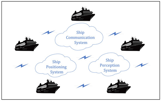
Figure 1.
The composition of the ship MANET system.
3.2. Design of Network Mode
The ship will be in various navigation scenarios dynamically during navigation, and the communication mode should be different in different navigation scenarios. We only consider the dynamic impact of other ships on ships. The main difference in the navigation scene lies in the number of target ships (TSs) within a certain range from own ship (OS) and the threat to own ship. Accordingly, we designed two kinds of network architecture as the main form of ship MANET, which is named intercommunication mode and cluster mode, and their topologies are called network topology and star-ring hybrid topology respectively.
3.2.1. Intercommunication Mode
This mode adopts a network topology as shown in Figure 2, which is suitable for ships in the seas far away from the coast, waterways, fishing areas, anchorages, and other special sea areas. Here, there are limited ships to meet, and communication is usually carried out for taking collision avoidance actions. Therefore, stable and high-quality communication is required. In network topology, there are many paths between nodes, collision and blocking can be reduced, and local failures do not affect the whole network. In this mode, ships in the network can communicate with any node in the network according to their needs. According to the characteristics of application scenarios, we name this mode an intercommunication mode. In such a network, the problem to be solved is how to send messages in the network.
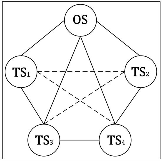
Figure 2.
Network topology of intercommunication mode.
As one of the important research directions of ad hoc network technology, a routing protocol is responsible for the decision-making of message dissemination. According to the different topologies of the network, the routing protocols of an ad hoc network can be divided into plane routing protocol and hierarchical routing protocol [28,29]. For the plane routing protocol, in the plane structure, there will be multiple paths between the source node and the destination node. All nodes are equal in status and they have identical functions. Plane routing protocols include all active routing protocols and on-demand routing protocols. The difference between them is the difference in route discovery strategies. In the active routing protocol, each node in the network should periodically exchange routing information with other nodes and each node should save the routing table [30]. When the network topology changes, the nodes broadcast the routing update information in the whole network, so that each node can continuously obtain the network information.
It is more typical to have Dynamic Source Routing Protocol (DSDV). The on-demand routing protocol is only created by the source node when routing is required, so the topology and the content of the routing table are established on demand. The routing is maintained during the communication process and will not be maintained after the communication is completed [31]. Common ones are Dynamic Source Routing Protocol (DSR) and Ad Hoc On-Demand Distance Vector Routing (AODV) [32]. We can choose the appropriate routing protocol according to the characteristics of the routing protocol and the needs of navigation.
3.2.2. Cluster Mode
This mode adopts a hybrid layered topology of star-ring, as shown in Figure 3, which is suitable for use in coastal areas and special sea areas such as coasts, waterways, fishing areas, and anchorages. We adopt this network mode when the number of ships within a certain range from the ship reaches a certain number. In this case, the number of ships is large, and the environmental awareness and communication capabilities of each ship are very different. Therefore, the idea of layering is used to construct the network. Clustering is an effective network topology management mode. Its hierarchical structure improves the scalability of mobile ad hoc networks and reduces the difficulty of grid management. We select the node with strong communication ability as the cluster head node, which is responsible for managing the nodes in the cluster and maintaining the stability of the cluster. The cluster heads are connected by loops. In this way, cluster-head ships can communicate with each other, and cluster members can only communicate with their cluster heads.
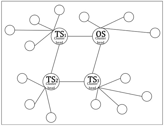
Figure 3.
Star-ring hybrid topology of cluster mode.
For such a network with a hierarchical topology, the nodes have different positions and functions. We need a cluster routing algorithm to solve the problem of cluster establishment and cluster maintenance in this ad hoc network mode, as well as the way of message broadcasting. Cluster establishment includes cluster head election, cluster member selection, cluster maintenance includes cluster head replacement, cluster member leaving, joining other clusters, cluster splitting and merging, etc. [33]. Typical hierarchical routing protocols mainly include Global State Routing Protocol (GSR), Dial On-Demand Routing (DDR), Host Specific Routing Protocol (HSR), etc. We can choose the appropriate clustering routing protocol according to the characteristics and navigation requirements of the clustering routing protocol.
3.3. Networking and Network Management
In this part, we will describe the network establishment process and network management methods. Firstly, a network trigger condition is established by using a model of the ship collision risk index. The ship will have an initialized network mode, and when the node joins, it can communicate. Due to the switching of the scene or the change in the number of ships, we can switch the networking mode. Finally, the node can be disconnected from the network and the ship can destroy the network after completing all interactive tasks. The specific algorithm flow is shown in the following Table 1.

Table 1.
Networking and network management algorithm flow.
3.3.1. Initialization of Own Ship Network
In the initialization state, the ship does not establish a network and is in a dormant state. We start building the net when there are ships around that pose a navigational hazard to our ship. When the natural environment, human dispatch, etc. are not considered, the Collision Risk Index (CRI) is usually used to evaluate the probability and severity of the collision between ships and other nearby ships [34]. Therefore, we use CRI to describe the navigation risk posed by other ships to our ship. However, the most fundamental factor for judging the risk of collision between ships is Distance to Closest Point of Approach (DCPA) when the two ships meet, so TCPA is the Time to the Closet Point of Approaching.
DCPA indicates whether there is a risk of collision between the two ships. If the DCPA is 0, the two ships will inevitably collide with speed and direction. The smaller the DCPA, the higher the risk. TCPA indicates the urgency of the collision risk. However, we hope to use one indicator to directly measure the collision risk, instead of using the two progressive indicators of DCPA and TCPA.
International Regulations for Preventing Collisions at Sea (COLREGS) does not clearly define the numerical value of collision risk. At present, there are many methods in the field of navigation to evaluate the collision risk of ships. Kearon first proposed to calculate the collision risk by weighting DCPA and TCPA. Xu Q. [35] summarizes three kinds of numerical models for collision risk calculation, including methods based on traffic flow theory, methods in the ship field, and methods based on DCPA and TCPA. In addition, Szlapczynski, R [36] proposed an analytical formula of collision risk parameters based on the ship field, including Degree of Domain Violation (DDV) and Time to Domain Violation (TDV), which have certain advantages over TCPA and DCPA. This paper adopts a classic model that uses five different factors to build the CRI [14], as shown in Formula (1), including distance and relative heading , relative speed , relative bearing , ship speed ratio .
Each factor has a corresponding membership function, which we use to express. At the same time, the contribution of each factor to the collision risk is different, and different calculation methods will have different coefficients. Then the calculation of CRI is Formula (2), and the relationship between coefficients is Formula (3).
3.3.2. Node Joining and Network Mode Selection
Setting up a networking trigger condition. The CRI between the first target ship and own ship can be expressed as , and is a threshold of CRI, when the two indexes meet Formula (4),
Own ship entered the networking state, so the target ship joined the network as the first node in the network, and own ship began to network with other ships around. We cannot only connect with the target ship whose CRI reaches the above threshold because the collision avoidance action between two ships is likely to have a negative impact on other ships, which is not conducive to the resolution of the situation of own ship. Therefore, we also need to screen the ship objects that are necessary for networking interaction. We set such a condition that for all ships within the communication range of this ship, as long as they meet Formula (5),
Then such a target ship will join the network as a new node.
In some narrow waters, such as channels for entry and exit, anchorage (mooring) grounds, fishing areas, traffic flow intensive areas, etc., it can be predicted that this ship will encounter many ships in a period. We suggest that, in such waters, the network mode of ships should choose the cluster mode and its star-ring topology so that we only need to have direct contact with a small number of major ships. In this case, it not only reduces the pressure of the overall network but also relieves the burden of a single node.
In open waters, we will not encounter a large number of ships that pose a danger to our ship in a short time normally, so we can consider choosing the intercommunication mode and its network topology.
3.3.3. Network Mode Switching
The condition for us to initialize and select the network mode is the water area to navigate. As mentioned above, the ship has chosen a network mode according to the navigation waters at that time when establishing the network. However, the number of other ships in both navigation waters and waters is dynamic, so it is necessary to design two switches to switch the network mode.
Switch from Intercommunication Mode to Cluster Mode
When navigating from open waters to heavy traffic waters or special waters, you can selectively switch modes. However, if the number of nodes in the network increases sharply or continuously, we need to switch to cluster mode.
During the switching process, the ship nodes with certain transmission and computing capabilities are first sorted to select the cluster head. After the cluster head node is determined, initialization information is broadcasted. Surrounding ship nodes send a request to enter the network after receiving the initialization message. After receiving the network entry message, the cluster head node determines the network entry conditions, replies with a confirmation message to join, and numbers them in the group. This completes the model switching.
Switch from Cluster Mode to Intercommunication Mode
Ships sailing out of heavy traffic waters and special waters and into open waters are often accompanied by a reduction in the number of ships around. At this time, we choose to switch to the intercommunication mode to realize the direct full connection of all nodes in the network.
During the switching process, the cluster head node first sends a cluster exit message to all nodes within the cluster. After receiving the cluster exit message, the ship node exits the cluster communication mode. All ship nodes publish network initialization information within their perception range, and establish node communication tables for all nodes within their perception range, completing the construction of intercommunication mode.
3.3.4. Disconnection of Nodes and Destruction of Network
There are usually the following situations for node disconnection. First, a target ship has completed the communication interaction task in the network, and it chooses to leave the network by itself, which can reduce the pressure on itself and the network. Second, one or several nodes are out of the communication range of other nodes. When the ship has successfully resolved the current situation, it then chooses to destroy the network.
4. Connectivity Properties of Ship MANET
For a ship’s ad hoc network, it is crucial to analyze its connectivity. To the best of our knowledge, there is no formal method to complete the modeling and connectivity analysis of ad hoc networks by considering marine ship motion scenarios. In this part, we can regard each ship as a node, and establish the ship MANET as a connectivity model with four attributes by studying the position of each node and the connection relationship between nodes.
Firstly, we analyzed the boundary conditions of node connectivity through the critical signal strength at the receiving end, then we studied the stability of the nodes and analyzed the relative motion situation of the nodes in combination with the ship encounter situation. On this basis, we study the possibility of node connectivity and the calculation method of link retention time.
4.1. Boundary Conditions of Node Connectivity
There will be losses when the signal propagates through the air. Assuming that an ideal isotropic antenna is lossless, according to the Frills Free Space Propagation Model, when a certain transmission and reception distance is d, the average power of the receiver is Formula (6):
where, is the transmit power of the signal at the transmission end, is the gain of the transmission antenna, is the gain of the receiving antenna, is the system fugitive coefficient, which refers to losses unrelated to propagation (such as transmission line attenuation, filter loss, antenna loss, etc.), and is the wavelength of the electromagnetic wave.
If we rewrite the above formula as the non-functional form of , the loss formula in the ideal state is as Formula (7):
where is the distance between the sending and receiving terminal, the unit is KM, the carrier frequency is , and the unit is MHz.
We do a simulation example to visualize this problem, as shown in Figure 4.
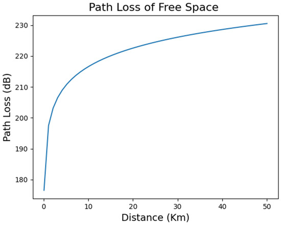
Figure 4.
Path loss in the Free Space Propagation Model.
Therefore, within the network, suppose there are two nodes and , separated by . According to the above model and formula, the signal of the message received by the receiver is Formula (8):
Generally, the position of the ship’s antenna is at the top of the bridge and the bridge is generally not in the center of the ship. The coverage of the antenna will not have the same coverage area in the forward and backward directions. However, for the convenience of research, we first assume that the coverage of the ship’s antenna at the transmission end is a circle with a radius of . Then the minimum signal strength of the receiver is , as shown in Formula (9):
The calculation of this threshold allows us to make it clear that even with the networking trigger conditions described above, networking can only be achieved if the receiver satisfies this condition.
4.2. Analysis of Motion Stability between Nodes
For ships with various motion situations encountered by own ship, we will not consider its ship mathematical model or movement model, and use another method to measure its stability in the network. According to the above, we know that the signal is attenuating during the propagation process, and the way of attenuation is not linearly decreasing with distance, but the signal strength is attenuating. We discretize the received signal strength value of the receiver, and use to represent the variation of the received signal at the receiver. For the convenience of research, we normalize through the max–min normalization method, so is expressed as Formula (10):
For such a discrete random variable, its variance is calculated as follows:
and
Through the above formula, the variation of the received signal power of the two nodes can be calculated. We import another variable :
Through a series of analyses of , the stability of the node motion can be judged. If becomes larger, becomes smaller, indicating that the stability between nodes becomes worse, otherwise becomes smaller and becomes larger, indicating that the stability between nodes becomes better. The quality of node stability reflects whether a node as a network member will cause drastic changes in network topology, affect the normal execution of routing protocols, whether it is a qualified cluster head, and so on.
4.3. Analysis of Movement Situation between Nodes
For ship encounters, there will be a variety of encounter scenarios. Through the comprehensive inductive analysis of the encounter scenarios, if we regard it as the relative motion between nodes, there will be two kinds of scenarios, namely approaching then leaving scenarios and leaving scenarios.
4.3.1. The Scenario of Approaching and Then Leaving
As shown in Figure 5, fix Ship 1 at the origin of the coordinate axis, its motion vector is , and for Ship 2, its motion vector is . Using the knowledge of the relative motion of objects, we can derive the relative motion line of Ship 2 when Ship 1 is stationary. In addition,, , and are the distance between Ship 1 and Ship 2 in the different stages of the process of navigation. It can be seen that is gradually decreasing, is gradually increasing, and is a minimum value. That is, the distance relationship between Ship 1 and Ship 2 is to approach first and then move away, and point is the closest point. According to the situation of ship encounters, almost all encounter scenarios, such as head-on, crossing, and overtaking situation, are approaching then leaving scenario.
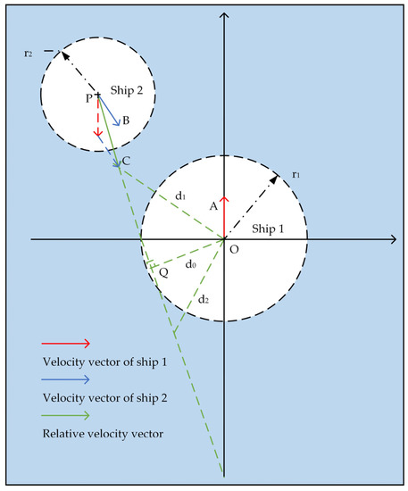
Figure 5.
The scenario of approaching then leaving.
4.3.2. The Scenario of Leaving
As shown in Figure 6, we also fixed Ship 1 at the origin of the coordinate axis, and according to the relative motion relationship, we made a relative motion line. In the case of the illustration, we can see that in terms of vector size, there is obviously , so as time changes, there are:
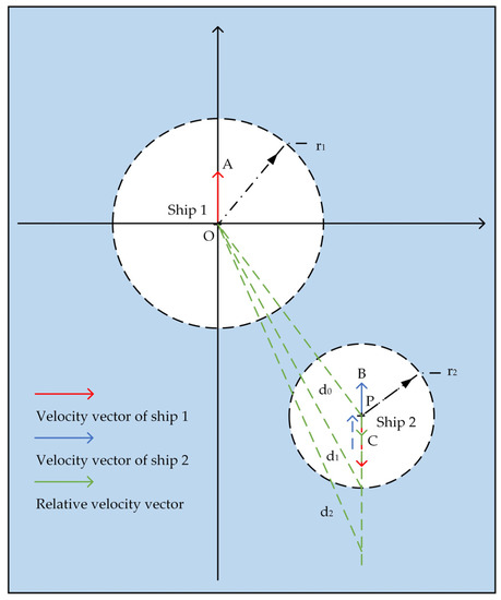
Figure 6.
The scenario of leaving.
That is, Ship 1 and Ship 2 are gradually moving away. In sailing, the two ships did not form an overtaking or overtaken relationship, and the speed of the front ship was greater than the ship behind.
4.4. Link Existence Possibility and Link Holding Time Calculation
During the voyage, the communication link can be maintained only when the ships are within the communication range; otherwise, the communication link will be interrupted. The possibility of link existence reflects whether a node can form an inter-ship link with other nodes in the network under the expected encounter scenario. It can be seen that this probability can be used as one of the references for the design of the clustering routing algorithm. The link hold time calculates how long an inter-ship link in the network can be maintained, that is, the two nodes are within the communication range of each other. This result is used as a time threshold, and the interaction process related to this node must be completed within the existence period of this link.
In the “approaching then leaving” scenario, as shown in Figure 7. In the figure, the red circle represents the communication range of Ship 1, the blue circle represents the communication range of Ship 2, the black dashed arrow represents the communication radius of the ship, the green dashed line represents the relative motion line of the two ships, the green dashed arrow represents the relative direction of motion and the purple solid line represents the distance between the two ships. It is assumed that at time , the target ship is at , the relative motion speed is , and the communication radius of Ship 1 and Ship 2 is and , respectively. If the two ships both keep course and speed, it can be seen that when Ship 2 sails to A (at time ), the two ships enter the communication range of each other and sail to B (at time ), the two ships leave each other’s communication range. After time , such as Ship 2 sailed to C at time , both ships were no longer within their communication range of each other. Then for ship 2, its connectivity probability at :
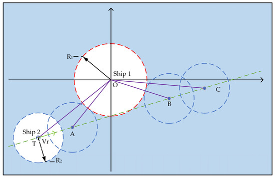
Figure 7.
Link calculation in approaching then leaving scenario.
It can be seen that when , the connectivity probability .
When Ship 2 moves along , its connectivity probability gradually increases within a certain time range.
When Ship 2 is between , .
When Ship 2 is at ,
It can be seen that the connectivity probability is gradually reduced when advancing along .
When , the connectivity probability .
And retention time:
The “leaving scenario” was shown as Figure 8. In the figure, the red circle represents the communication range of Ship 1, the blue circle represents the communication range of Ship 2, the black dashed arrow represents the communication radius of the ship, the green dashed line represents the relative motion line of the two ships, the green dashed arrow represents the relative direction of motion and the purple solid line represents the distance between the two ships. At the initial time , the target ship is at , and the relative motion speed is . Similarly, the communication radius of Ship 1 and Ship 2 is R1 and , respectively. Ship 2 proceeds along the current relative motion line. At time , Ship 1 and Ship 2 are still connected, so at B at the time , it is a connected boundary.
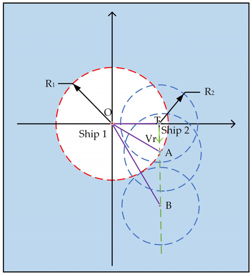
Figure 8.
Link calculation in leaving scenario.
When Ship 2 sails between and , there is .
After leaving B, the connectivity probability gradually becomes smaller and finally has .
5. Analysis of Node Transmission Capacity
Modern wireless communication systems basically include the comprehensive application of two basic theories. One is the Frills Free Space Propagation Model mentioned above, and the other is Shannon Formula. According to Shannon Formula, as follow Formula (19), the maximum information transmission rate of a specific channel:
where is the channel bandwidth, is the average power of the signal transmitted in the channel, and is the Gaussian noise power within the channel (unit: W).
Generally, the maximum amount of information that a channel can reliably transmit per unit of time is also called channel capacity. According to Formula (19), we can see that the channel capacity is proportional to the bandwidth and is affected by the signal-to-noise ratio. From the perspective of wireless communication technology, and shipborne communication equipment, our ship MANET is a complex system that can be transmitted and received at multiple points. This means that the signal transmitted by one node is noise interference to some other receiving points. An increase in noise signal power means a decrease in channel capacity. Other transmission nodes will increase their transmission power to ensure their own channel capacity. Therefore, if this situation is not limited, all nodes will be submerged by noise and the system will be crashed. Therefore, the selection of signal transmission distance, power, and channel of each node is the result of a balance of various factors.
In this chapter, we test the connectivity of ship MANET through the parameters such as node coverage distance, channel capacity, and transmission power. Combined with the construction of ship MANET, it needs to be changed. As mentioned above, each node is both a transmission node and a receiving node. First of all, in a continuous communication process, such as the communication task of a collision avoidance maneuvering in the network, multiple ships in the network will receive and transmit signals many times during this period, but only the signals of their interaction objects are useful to them, and the rest can be defined as interference for the time being. Therefore, in addition to noise, signal interference is the accumulation of signal interference of non-interactive objects. Secondly, according to the Frills Formula mentioned above, the attenuation of the signal is related to the distance, so we can use the Formula (19) to express the capacity of a node:
where, is the transmission power of the node, is the distance from the transmission node to the destination node, is noise, is the power of the signal transmitted by the unexpected node of the target node, is the distance from them to this node. Using formula 19, we perform the analysis of node transmission capacity, including calculation of capacity of nodes at different values of power, calculation of the capacity of nodes for fixed capacity, and calculation of capacity of nodes for different values of capacity.
5.1. Find the Distance and Number of Nodes in Each Radius
During sea navigation, ships can discover other ships through radar and other navigational aids, and check the number, position, and distance of target ships. However, from an interactive perspective, we need to search for the target ship through communication devices in the ship MANET. Therefore, in a marine scene, we need to determine the number of nodes in the network and their distance from OS. The experimental parameters are shown in Table 2. We take the location of the ship as the central node, that is, the coordinates of our ship are , and, then, some nodes are randomly distributed within a certain range of the coordinate axis, which represents a sea area, and these nodes represent TSs in the sea area, thus simulating a scene in which ships encounter at sea at random. This allows us to calculate and list the distance between the center node and each other node. Suppose that in a circular sea area with a radius of 20 nautical miles, for the central node, that is OS, its transmission coverage radius can cover the farthest node in the above range in steps of 1 nautical mile. As shown in Figure 9, we can find the number of nodes under different transmission coverage radii. Through several groups of random tests, we can see that with the increase of the launch radius, the number of other ships that this ship can connect in a sea area will increase.
Table 2.
Experimental parameters and value of Section 5.1.
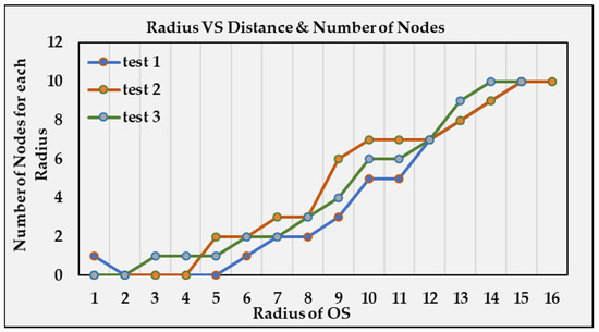
Figure 9.
Radius vs. distance & number of nodes.
5.2. Calculation of Capacity of Nodes at Different Values of Power
Suppose there are four randomly distributed nodes in a sea area of 20 × 20 square nautical miles. ,. The experimental parameters are shown in Table 3. We select one of the nodes as OS, and the other three nodes are the TSs. When own ship is interacting with a target ship, the signals of the other two ships interfere. Suppose that the transmission power of OS has a total of ten kinds of power, from one to ten, and three other ships set three groups of power according to the difference of signal power between them, namely, 1, 2, 3; 3, 6, 9; 1, 5, 10. The calculation is based on Formula (19).
Table 3.
Experimental parameters and value of Section 5.2.
According to these three groups of experiments, as shown in Figure 10, for the fixed signal interference of other ships, the ship increases the transmission power, which makes the channel capacity of the ship continue to increase. When the ship transmits signals at a certain power, it is not that the smaller the power of the interference signal, the larger the channel capacity. This means that the power of our ship MANET equipment is not always large or small, but the optimal value should be selected within a certain range according to the experimental results. Notably, a linear functional relationship between number of nodes and radius of OS does not exist.
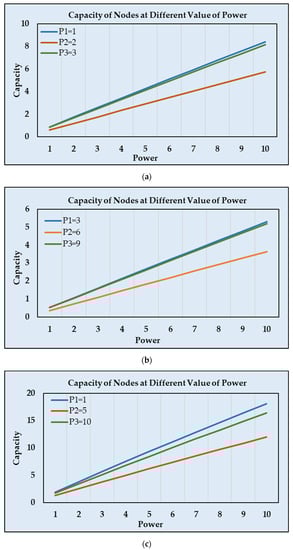
Figure 10.
The capacity of nodes at different values of power.
5.3. Calculation of Capacity of Nodes for Fixed Capacity
Similarly, it is assumed that in a sea area of 20 × 20 square nautical miles, the OS’s position is . The complete experimental parameters are shown in Table 4. When the channel capacity can only be fixed due to environmental constraints, we need to know whether the ship can connect to all nodes that need to be connected. Take the channel capacity of OS as three fixed values, assuming 1.5, 4.5, and 7.5. In addition, another nine target nodes in the sea area are randomly distributed, and their power is also random within one to ten. The setting of the location and the number of other ships well simulate the scene of an encounter at sea under random conditions. The random power of other ships can represent the heterogeneous communication equipment of ships, thus conforming to the multimodal characteristics of ship MANET. The calculation is based on Formula (19).
Table 4.
Experimental parameters and value of Section 5.3.
As shown in Figure 11, according to the three experiments, it can be seen from that under the fixed channel capacity of the ship, it is not necessarily connected to all nodes.
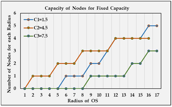
Figure 11.
The capacity of nodes for fixed capacity.
5.4. Calculation of Capacity of Nodes for Different Values of Capacity
The location of own ship is , set nine target ship nodes in addition to this ship, and their positions are random. The complete experimental parameters are shown in Table 5. We change the channel capacity threshold of OS and set three different values for it. Similarly, according to the difference in signal power between them, three groups of control experiments were set up for small, medium, and large respectively. The setting values are 1, 1.5, 2; 3, 6, 9; 1, 5, 9. The calculation is based on Formula (19).
Table 5.
Experimental parameters and value of Section 5.4.
The experimental results shown in Figure 12, for a fixed channel capacity, the number of connectable nodes does not necessarily increase with the increase of the transmission radius of the ship, only nodes below the threshold will be connected. Additionally, the larger the difference between thresholds, the greater the difference in the number of nodes that can be connected.
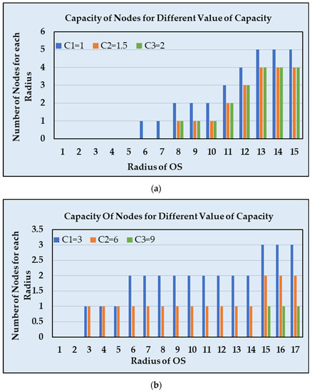
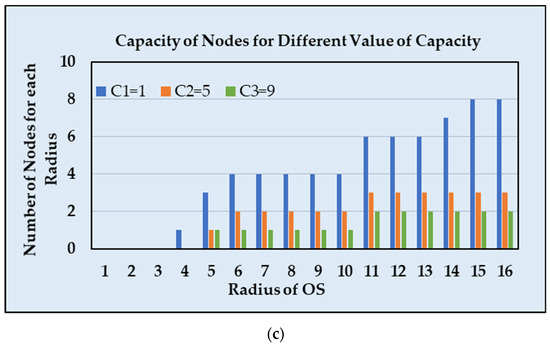
Figure 12.
The capacity of nodes for different values of capacity.
6. Result and Conclusions
The development of autonomous ships is the general trend and the constant pursuit of the shipping industry. Multi-modal ship scenarios are inevitable in future maritime scenarios. To deal with the interaction between ships under various types of ships and heterogeneous communication equipment, an ad hoc network is obviously an excellent choice. This paper analyzes the relevant research on the development history and navigation status of autonomous ships, ad hoc network, ship communication, and ship interaction, proposes to build a ship MANET dominated by autonomous ships and explains the system composition, network mode, selection, and switching methods, and management methods of the network. Based on the two pillar theories of wireless communication, the network is established as a connectivity model and its attributes are analyzed, the transmission capacity of nodes in the network is also studied. These two mathematical models well support the feasibility of building and using ship MANET. In conclusion, in the navigation scenario of multi-modal ships, it is feasible and effective to realize ship-to-ship interaction by establishing a ship MANET guided by autonomous navigation ships.
Author Contributions
Conceptualization, S.W.; funding acquisition, Y.Z. (Yingjun Zhang); methodology, Z.L.; supervision, Y.Z. (Yingjun Zhang); validation, Y.Z. (Yiyang Zou); writing—review and editing, X.W. All authors have read and agreed to the published version of the manuscript.
Funding
This work was supported by the National Natural Science Foundation of China (Grant No. 52231014).
Institutional Review Board Statement
Not applicable.
Informed Consent Statement
Not applicable.
Data Availability Statement
Not applicable.
Conflicts of Interest
The authors declare no conflict of interest.
References
- Sanchez-Gonzalez, P.L.; Díaz-Gutiérrez, D.; Leo, T.J.; Núñez-Rivas, L.R. Toward Digitalization of Maritime Transport? Sensors 2019, 19, 926. [Google Scholar] [CrossRef]
- Felski, A.; Zwolak, K. The Ocean-Going Autonomous Ship—Challenges and Threats. J. Mar. Sci. Eng. 2020, 8, 41. [Google Scholar] [CrossRef]
- Wu, Q.; Wang, T.; Diaconeasa, M.A.; Mosleh, A.; Wang, Y. A Comparative Assessment of Collision Risk of Manned and Unmanned Vessels. J. Mar. Sci. Eng. 2020, 8, 852. [Google Scholar] [CrossRef]
- Höyhtyä, M.; Martio, J. Integrated Satellite–Terrestrial Connectivity for Autonomous Ships: Survey and Future Research Directions. Remote Sens. 2020, 12, 2507. [Google Scholar] [CrossRef]
- Jiang, Q.; Manivannan, D. Triangle-Based Routing for Mobile Ad Hoc Networks. Pervasive Mob. Comput. 2016, 33, 108–126. [Google Scholar] [CrossRef]
- Walikar, G.A.; Biradar, R.C. A Survey on Hybrid Routing Mechanisms in Mobile Ad Hoc Networks. J. Netw. Comput. Appl. 2017, 77, 48–63. [Google Scholar] [CrossRef]
- Moussaoui, A.; Boukeream, A. A Survey of Routing Protocols Based on Link-Stability in Mobile Ad Hoc Networks. J. Netw. Comput. Appl. 2015, 47, 1–10. [Google Scholar] [CrossRef]
- Cho, C.; Ahn, S. Efficient Maintenance of AODV Routes in the Vehicular Communication Environment with Sparsely Placed Road Side Units. Mob. Inf. Syst. 2018, 2018, 6252907. [Google Scholar] [CrossRef]
- Systems, M.V.I.; Le, T. A Distributed Channel Access Scheme for Vehicles. IEEE Trans. Cogn. Commun. Netw. 2020, 6, 1297–1307. [Google Scholar]
- Ramamoorthy, R.; Thangavelu, M. An Enhanced Hybrid Ant Colony Optimization Routing Protocol for Vehicular Ad-Hoc Networks; Springer: Berlin/Heidelberg, Germany, 2021; ISBN 0123456789. [Google Scholar]
- Alheeti, K.M.A.; Mcdonald-maier, K. An Enhanced AODV Protocol for External Communication in Self-Driving Vehicles. In Proceedings of the 2017 Seventh International Conference on Emerging Security Technologies (EST), Canterbury, UK, 6–8 September 2017. [Google Scholar]
- Sami, O.; Lakas, A.; Zhou, F.; Güne, M. A Survey on Position-Based Routing Protocols for Flying Ad Hoc Networks (FANETs). Veh. Commun. 2017, 10, 29–56. [Google Scholar] [CrossRef]
- Sahingoz, O.K. Networking Models in Flying Ad-Hoc Networks (FANETs): Concepts and Challenges. J. Intell. Robot. Syst. 2014, 74, 513–527. [Google Scholar] [CrossRef]
- Shaobo, W.; Yingjun, Z.; Lianbo, L. A Collision Avoidance Decision-Making System for Autonomous Ship Based on Modified Velocity Obstacle Method. Ocean Eng. 2020, 215, 107910. [Google Scholar] [CrossRef]
- Aslam, S.; Michaelides, M.P.; Herodotou, H. Internet of Ships: A Survey on Architectures, Emerging Applications, and Challenges. IEEE Internet Things J. 2020, 7, 9714–9727. [Google Scholar] [CrossRef]
- Tian, Z.; Liu, F.; Li, Z.; Malekian, R.; Xie, Y. The Development of Key Technologies in Applications of Vessels Connected to the Internet. Symmetry 2017, 9, 211. [Google Scholar] [CrossRef]
- Working Document toward a Preliminary Draft New Recommendation ITU-R M. [VDES]* Technical Characteristics for a VHF Data Exchange System in the VHF Maritime Mobile Band. 2014. Available online: https://www.iala-aism.org/content/uploads/2016/06/enav16_14_2_22_wg3_pdnr_annex_6_v0.pdf (accessed on 4 April 2023).
- Lázaro, F.; Raulefs, R.; Wang, W.; Clazzer, F.; Plass, S. VHF Data Exchange System (VDES): An Enabling Technology for Maritime Communications. CEAS Space J. 2019, 11, 55–63. [Google Scholar] [CrossRef]
- Surendran, S.; Ramesh, M.V.; Montag, M.J.; Montresor, A. Modelling Communication Capability and Node Reorientation in Offshore Communication Network. Comput. Electr. Eng. 2020, 87, 106781. [Google Scholar] [CrossRef]
- Xu, Z.; Xiaoyang, X.; Liwei, S.; Jinyu, Z.; Wu, Z.; Wenjing, D. Performance Analysis of Sea Unmanned Ship Routing Protocol Based on Ad Hoc Network. In Proceedings of the 2019 International Conference on Information Technology and Computer Application (ITCA), Guangzhou, China, 20–22 December 2019; Volume 221–224. [Google Scholar] [CrossRef]
- Wang, S.; Zhang, Y.; Zhang, X.; Gao, Z. A Novel Maritime Autonomous Navigation Decision-Making System: Modeling, Integration, and Real Ship Trial. Expert. Syst. Appl. 2023, 222, 119825. [Google Scholar] [CrossRef]
- Ma, Y.; Zhao, Y.; Incecik, A.; Yan, X.; Wang, Y.; Li, Z. A Collision Avoidance Approach via Negotiation Protocol for a Swarm of USVs. Ocean. Eng 2021, 224, 108713. [Google Scholar] [CrossRef]
- Hu, Q.; Yang, C.; Chen, H.; Xiao, B. Planned Route Based Negotiation for Collision Avoidance Between Vessels. Int. J. Mar. Navig. Saf. Sea Transp. 2008, 2, 363–368. [Google Scholar]
- Szlapczynska, J. Data Acquisition in a Manoeuver Auto-Negotiation System. TransNav Int. J. Mar. Navig. Saf. Sea Transp. 2015, 9, 343–348. [Google Scholar] [CrossRef]
- Szlapczynska, J. Propozycja Systemu Auto-Negocjacji Manewrów Statków Korzystającego z Metod Optymalizacji Wielokryterialnej Oraz Matematycznej Teorii Ewidencji. Logistyka 2015, 6, 10375–10384. [Google Scholar]
- Hornauer, S.; Hahn, A. Towards Marine Collision Avoidance Based on Automatic Route Exchange; IFAC: New York, NY, USA, 2013; Volume 46, ISBN 9783902823526. [Google Scholar]
- Hornauer, S. Decentralised Collision Avoidance in a Semi-collaborative Multi-agent System. In Multiagent System Technologies; Springer: Berlin/Heidelberg, Germany, 2013; pp. 412–415. [Google Scholar]
- Sharma, V.; Ganpati, A. Comparison of Topology Based-Routing Protocols in Wireless Network. J. Multimed. Inf. Syst. 2019, 6, 61–66. [Google Scholar] [CrossRef]
- Gil, M. A Concept of Critical Safety Area Applicable for an Obstacle-Avoidance Process for Manned and Autonomous Ships. Reliab. Eng. Syst. Saf. 2021, 214, 107806. [Google Scholar] [CrossRef]
- Perkins, C.E.; Bhagwat, P. Highly Dynamic Destination-Sequenced Distance-Vector Routing (DSDV) for Mobile Computers. ACM SIGCOMM Comput. Commun. Rev. 1994, 24, 234–244. [Google Scholar] [CrossRef]
- Johnson, D.B.; Maltz, D.A. DSR: The Dynamic Source Routing Protocol for Multi-Hop Wireless Ad Hoc Networks. Ad Hoc Netw. 2001, 5, 139–172. [Google Scholar]
- Tuo, M.F.; Che, M. Research on Routing Protocol of Mobile Ad Hoc Network. EDP Sci. 2016, 05022, 3–5. [Google Scholar] [CrossRef]
- Informatics, S. Random Access Technique for Unmanned Surface Vehicle. Ad-Hoc Netw. 2020, 41, 29–35. [Google Scholar] [CrossRef]
- Wang, S.; Zhang, Y.; Huo, R.; Mao, W. A Real-Time Ship Collision Risk Perception Model Derived from Domain-Based Approach Parameters. Ocean Eng. 2022, 265, 112554. [Google Scholar] [CrossRef]
- Management, T. A survey on ship collision risk evaluation. Promet-Traffic Transp. 2014, 26, 475–486. [Google Scholar]
- Szlapczynski, R.; Szlapczynska, J. An Analysis of Domain-Based Ship Collision Risk Parameters. Ocean Eng. 2016, 126, 47–56. [Google Scholar] [CrossRef]


Disclaimer/Publisher’s Note: The statements, opinions and data contained in all publications are solely those of the individual author(s) and contributor(s) and not of MDPI and/or the editor(s). MDPI and/or the editor(s) disclaim responsibility for any injury to people or property resulting from any ideas, methods, instructions or products referred to in the content. |
© 2023 by the authors. Licensee MDPI, Basel, Switzerland. This article is an open access article distributed under the terms and conditions of the Creative Commons Attribution (CC BY) license (https://creativecommons.org/licenses/by/4.0/).