Abstract
Reduced-order stick models are frequently employed to obtain dynamic amplification factors of self-elevating units (SEU), while the full-order finite element (FE) models are used for quasi-static analyses. This paper develops an efficient framework to create structural digital twins for SEUs by combining both stick models and full-order FE models. A stick model and a detailed FE model of an in-house developed generic SEU are established, respectively, following the standard industry guideline. Dynamic analyses are performed for the stick model based on the modal superposition method. Assuming that the stick model contains the key dynamic characteristics of the full-order FE model, the modal participation factors are multiplied by the corresponding mode shapes of the full FE model to derive the global dynamic responses of the entire SEU. The derived nodal displacements are imposed on the full-order model to obtain the member stresses. The global responses and member stresses are benchmarked with the results from a direct full-order dynamic FE analysis for various environmental conditions. The presented framework is found to significantly increase the efficiency of the simulation while retaining a similar accuracy, and it forms a critical step for the ongoing development of digital twins of fixed offshore structures.
1. Introduction
Self-elevated units are widely employed in the oil and gas industry for offshore drilling because of their flexibility and mobility. The SEU for offshore drilling is known as a jack-up, which is normally formed by a rigid buoyant triangular hull and three steel truss or tubular legs [1]. The movable legs can be jacked through the hull, and the entire platform can be transported around through either dry tow or wet tow. Conventional SEUs have been operating for decades and the design procedures are well-documented in the industry standards [2,3,4]. However, accidents, such as punching through, are continuously reported in recent years [5,6]. In addition, there is also a challenge in predicting the remaining life of aging jack-up oil rigs and ensuring their safety in the remaining services, especially for those operating in harsh sea states [7].
In recent years, the increase in the interest of renewable energies has led to a booming demand of installation of offshore wind turbines. To install large wind turbines, wind turbine installation vessels (WTIVs) are frequently used which are in the form of self-elevating units. Purpose-built jack-up vessels have become a major type of WTIV in the offshore wind market [8]. These WTIVs have a vessel shape and are normally equipped with four or six legs. It is also interesting that conversion from conventional jack-ups to WTIVs has started to appear in recent years because of the demand. Large deck space and heavy lifting capacity are also required, which differentiate WTIVs from their counterparts in the oil and gas industry. The interaction between the WITVs and large wind turbine blades is also a unique problem [9]. Another noteworthy difference is the operational limits. WTIVs normally have more frequent jack-up operations for turbine installations than conventional jack-ups for drilling operations. The tighter profit margin in the offshore wind industry calls for wider operational window for WTIVs, which also means an increase in the operating envelope of such platforms, particularly in harsh sea states [10]. This tendency poses new challenges in maintaining safe and reliable operations for SEUs.
Part of the above-mentioned challenges were investigated in the past decades covering linear or non-linear boundary conditions, soil–spudcan interactions, and different combinations of environmental actions [11,12,13,14]. The impact between the seabed and legs of SEUs and interactions between waves and hulls of SEUs are critical for in-place operations [10,15,16]. Attention was specially paid to the dynamic performance of jack-up rigs in transiting, especially during wet towing [17,18,19,20,21]. The stability during wet towing of SEUs is also critical. Experimental studies and stochastic numerical analyses were studied for both intact and damaged conditions of jack-up rigs [22,23,24,25]. In general, many of these studies were focused on wave–structure interactions. The ice–structure interactions for SEUs were also investigated in shallow water conditions [26]. These studies helped the industry build up methodologies and standards for evaluating dynamic responses of SEUs.
With the rapid development of digitalization and automation technologies, structural digital twins of the SEUs play an important role in overcoming these challenges. One important function of the structural digital twin is the capability to predict the dynamic responses of SEUs efficiently, which will therefore provide an accurate forecast of safe operations and remaining life predictions [27,28]. In the recent research work in the Technology Center for Offshore and Marine, Singapore (TCOMS), structural digital twins of SEUs were developed to improve the operational efficiency, reduce life-cycle expenditures, and enhance productivity of SEUs in complex environments and challenging operating conditions. The development work involves extensive numerical modeling and a series of basin-scale model tests for validation and demonstration purposes. The developed digital twin aims to help the industry to better manage the full life cycle of SEUs and other types of fixed offshore structures.
It is found that the existing method for dynamic analysis of SEUs is time-consuming and not efficient for structural digital twin development. The conventional method in the industry involves a two-step method. A separate dynamic analysis using a simplified reduced-order stick model is conducted first to obtain dynamic amplification factors (DAFs), followed by a static strength analysis using a full-order finite element (FE) model. The methodology for the analysis is summarized in the industry guidelines and recommended practices [2,3,4,29]. Apart from the two-step method, it is possible to conduct a direct time-domain dynamic analysis using commercial software, such as ABAQUS [30]. However, time-domain dynamic analysis, especially if aimed at reliability analysis, will introduce high computational burden because of the considerable number of computational elements and sea states.
To improve the efficiency in dynamic analysis of SEUs, a new framework is developed in this paper. The framework utilizes both stick models and full-order FE models for their respective advantages. Namely, the stick model is more efficient, while the full-order FE model is more detailed. Instead of transferring the DAF or conducting direct analysis in full-order FE models, modal participation factors are transferred from the stick model to the corresponding full-order FE model to obtain the dynamic responses of the entire SEU. To obtain the nodal forces and member forces/stresses, the nodal displacement is then imposed on the full-order FE model for a quasi-static analysis. The details of the framework will be further introduced in the next section. It is noted that the presented framework is based on linear assumptions for the structures and the boundary conditions, while the external excitations could be either linear or non-linear.
To validate the proposed framework, a case study is presented in this paper. The case study is based on an in-house developed generic SEU. The SEU is developed for a demonstration of digital twins and has been used for both numerical simulation and model tests in TCOMS [16]. The three-dimensional drawings of the SEU can be found in Figure 1. The SEU is a simplified jack-up with three truss legs and spudcans. The equipment on the deck and cantilever are simplified as mass blocks at appropriate elevations. The natural frequencies of the SEU are designed to be reasonable by comparing them with the available information on existing jack-up rigs. Unless otherwise specified, all the parameters presented in this paper are for prototype-scale.
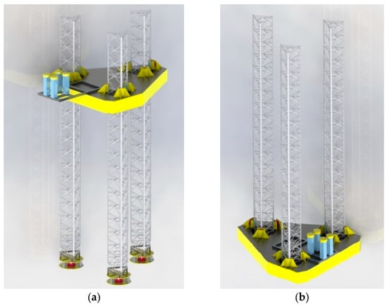
Figure 1.
Conceptual design of the in-house developed generic self-elevating unit: (a) elevated condition, (b) transit condition.
The framework proposed in this paper is expected to be much more efficient than the conventional method while maintaining acceptable accuracy. It is suitable for screening critical cases for global dynamic responses and stresses of SEU units, which can be followed by a detailed full-order FE analysis. The proposed framework can be a critical intermedium step for building up a digital twin of fixed offshore structures that requires efficient online model updating and predictions. In addition, to the best of the authors’ knowledge, it is the first time that the stick model and full-order model are combined for the dynamic analysis of SEUs.
The paper is organized as follows. The detailed framework and methodologies are presented in Section 2. The numerical models, namely the stick model and full-order model and the corresponding benchmarking cases, are introduced in Section 3. This is followed by results and discussions in Section 4. In Section 5, concluding remarks for the presented works are presented.
2. Framework for Efficient Dynamic Analysis of SEU
The workflow of the proposed framework is shown in Figure 2. In addition to the linear assumption of the structure, it is required that the dominant global modes, i.e., both the corresponding natural frequencies and mode shapes of the stick model and the full-order FE model, are equivalent. This is not difficult to achieve if the two models are similar in their dynamic characteristics. To verify the mode shape and natural frequencies, an eigen analysis for both models is required after the models are built.
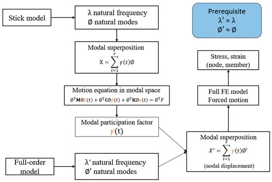
Figure 2.
Workflow of the proposed framework.
Under the above assumptions, the motions of the stick model are represented by linear modal superposition, as shown in Equation (1):
where is the motion vector; is the vector of modal participation factor; is time; and is the mode shape vector of the rth mode. Substituting Equation (1) into the motion equation of the stick model, and expressing the motion in matrix form, the motion equation in modal space can be expressed as follows:
where and are the mode shape matrix and its transpose; , , and are the mass, damping, and stiffness matrix of the stick model, respectively; and are the acceleration and velocity vector; and is time. is introduced in the form of Rayleigh damping with two damping coefficients and , i.e.,
The modal participation factor can therefore be solved by implementing a numerical integration method, such as the Runge–Kutta method. Once the modal participation factor is determined, the motions and nodal displacement of the full-order model can be expressed as
where is the motion vector of the full-order model; is the mode shape vector of the rth mode of the full-order model. The stresses can be derived following basic finite element theories or by simply imposing the motion to the full-order model to perform quasi-static analysis. For simplicity, we impose the nodal displacement of all the nodes on the full-order FE model and perform quasi-static analysis in this paper.
The proposed framework is implemented in a set of in-house developed codes using MATLAB environment. More descriptions of the models are presented in the next section.
3. Numerical Models
Two sets of numerical models are built for the generic SEU with simplifications. The main particulars of the generic SEU can be found in Table 1 below. The stick FE model is based on the open-source code Stabil [31], while the full-order FE model is built in ABAQUS 2021 [30].

Table 1.
Main particulars of the generic self-elevating unit.
3.1. Full-Order FE Model
The full-order FE model of the generic SEU is shown in Figure 3a. The truss legs are modeled in detail with two-node linear beam elements. The legs consist of all structural members such as chords, horizontal, diagonal, and internal braces. The hull is simplified by zero-mass dummy beams with a very large Young’s modulus to maintain rigidity. The mass and mass distribution of the hull and equipment are modeled by point mass at their corresponding center of gravity. The final mass properties of the model are carefully checked by comparing them with the initial design. The connections between legs and hull are modeled as linear springs in the present model, which are simplified from the non-linear prototype design. The spudcan constraints are simulated as pin boundary conditions. Rotational springs are introduced in the rotational directions, namely Rx, Ry, and Rz. The rotational stiffness value is 42,360 Nm/rad for Rx and Ry and 4236 Nm/rad for Rz. The model has 1807 nodes and 10,842 degrees of freedom.
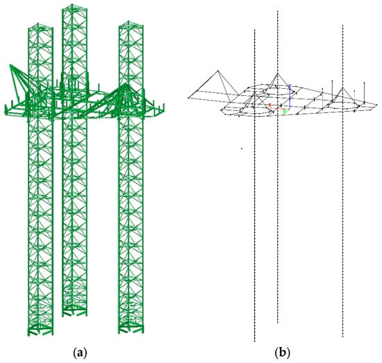
Figure 3.
Full-order FE model of the jack-up (a) and the equivalent stick model (b).
The hydrodynamic loads determined from the Morison formula [32] are applied to the FE model. The Morison forces on a unit length moving cylinder can be calculated through Equation (5):
where is the water density; is the inertia coefficient; is the drag coefficient; is the diameter of the cylinder; and are the velocity and acceleration of the flow, respectively; and and are the velocity and acceleration of the moving cylinder. = 1.4 and 1.0 are assumed for the chord and bracing member, respectively, while = 2.0 is assumed for all the structural members for the benchmarking study, assuming all these members are smooth tubular. The selection of the values for drag coefficient and inertia coefficient is according to the literature on a laboratory experiment [18] for the ease of benchmarking study in the future. The values in that experiment are different from the suggested values in the industry guidelines [2,4]. The difference is related to the effects of non-tubular chord teeth in a real SEU structure and scaling effects in the model test. The selection of these values has no significant impact on the benchmarking study of the developed efficient numerical framework. Once the method is validated, it is straightforward to update the drag coefficient and inertia coefficient for the real SEUs following the same procedure presented in this paper.
3.2. Stick Model
The stick model of the generic SEU is shown in Figure 3b. The stick model is a simplified model of the entire SEU structure with equivalent dynamic behaviors. The truss legs are simplified as beams with equivalent structural properties and hydrodynamic coefficients. The procedure for deriving these parameters is well documented in industry guidelines, such as ABS [2] and SNAME [4]. A simple explanation is given here for completeness.
The procedures to determine the structural properties are shown in Figure 4. Axial load , bending moment , and shear load F are separately and sequentially applied to the free end of a single truss leg and the equivalent homogenous cantilever beam in order to derive the structural properties, namely the equivalent sectional area , second axial moment of area about , and , and shear area . The structural properties for the equivalent beams are determined such that the deformation of the cantilever is the same as that of the truss legs. A summary of the beam properties is presented in Table 2.
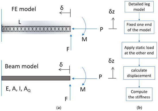
Figure 4.
Procedure for deriving equivalent stick model for SEUs: (a) application of forces for deriving equivalent stiffness, (b) flowchart for deriving equivalent stiffness.

Table 2.
Hydrodynamic coefficient and structural properties for the stick model legs.
The hydrodynamic coefficients, namely and , are derived to achieve the same hydrodynamic loads on the legs per unit length. The contribution from both bracing members and chord members are included in the calculation. Because of the different projection area of these members, the equivalent and varies for different wave headings. For a 0 deg wave heading, the equivalent and are equal to 1.770 and 3.117, respectively. Note that a 0 deg wave heading is defined when the waves propagate from the fore side to the aft side of the hull.
In addition, the mass of the legs is also equivalently modeled in the stick model to make sure the distribution of inertia between the full-order FE model and stick model is equivalent. A summary of the hydrodynamic coefficients and structural properties of the beams in the stick model is presented in Table 2. The stick model comprises 418 nodes and 459 beam elements. The beams are linear two-node elements based on Timoshenko beam theory.
3.3. Verifications of Stick Model and Full-Order FE Model
Static analysis was conducted first to ensure the global stiffness properties of the two models are equivalent. This was followed by modal analysis to verify that the equivalent stick model has the same dynamic performance as the full-order model. The comparison of the natural frequencies and the corresponding mode shapes are presented in Table 3 and Figure 5, respectively. In general, very good agreement can be found between the stick model and the full-order model, and the differences in the natural frequencies are within 2%, indicating that the stick model can well capture the major modes of the SEU.

Table 3.
Natural frequencies of the SEU from stick model and full-order model (unit: Hz).
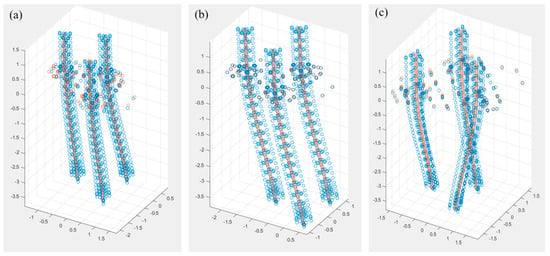
Figure 5.
Comparison of mode shapes between stick model and full-order FE model (enlarged by 100 times): (a) first mode shape, (b) second mode shape, and (c) third mode shape.
4. Results and Discussions
Following the procedures presented in Section 2, dynamic analyses were conducted for the SEU in regular waves and irregular waves. The analyses were also conducted for the full-order FE model to verify the proposed method. The environmental conditions for the dynamic analyses are listed in Table 4. Two frequencies were selected for regular waves: one wave frequency in the resonant range and the other frequency outside the resonant range of the SEU. Comparisons were made in terms of hull rigid-body motions, nodal displacement, and axial stresses in chord members and bracing members at selected locations along the forward leg. The locations of the selected nodes and members are shown in Figure 6a–c.

Table 4.
Wave parameters for the benchmarking study between the proposed method and ABAQUS.
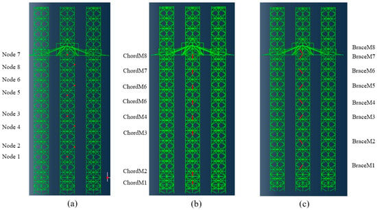
Figure 6.
Location of (a) selected nodes, (b) chord members, and (c) bracing members on forward legs of the SEU for validation comparison (ChordM1 stands for chord member 1, BraceM1 stands for bracing member 1).
4.1. Dynamic Responses in Regular Waves
The hull motion responses under regular wave excitations outside the resonant range and at the resonant frequency are shown in Figure 7a,b, respectively. The hull motion is taken from the geometrical center of the hull on the deck that is denoted as node 156 of the full FE model. Only surge motions are presented because they are the governing motions for the SEU under head sea conditions. It can be found that when the wave excitation is outside the resonant frequency range of the SEU, the proposed method provides very close results to those of the full-order FE model. When the wave excitation is close to the resonant frequency of the structure, a notable difference in the surge motion can be observed, due to additional damping from the relative velocity formulation which is considered by default in ABAQUS but not present in the stick model. Therefore, additional damping for the stick model is necessary to ensure the two models are equivalent. The additional damping is determined through trial-and-error iterations for the regular wave case with a wave frequency close to the resonant frequency of the structure. Note that the damping is only critical when the resonant motion of the SEU is dominant.

Figure 7.
Comparison of the time history of hull displacement in surge under regular wave excitations outside and inside the resonant frequency range (a,b).
The nodal displacement along the forward legs is presented in Figure 8. The results are shown when the responses reach a steady state for a wave frequency of 0.667 Hz. It can be found that the nodal displacements obtained from the simulations following the proposed framework at eight different locations are consistent with those from the direct dynamic analysis. In general, the difference between the proposed method and the conventional direct FE simulation is found within 2%, demonstrating a very good agreement. From these responses, it can be found that the surge motion in general is dominated by the second mode of the structure. Under the regular wave excitations, the maximum surge motion can be up to 1.5 m. The maximum surge appears at the nodes close to the hull.
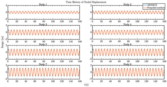
Figure 8.
Comparison of the time history of nodal displacement in surge under regular wave excitations.
The axial member stresses of the selected bracing members and chord members of the legs are presented in Figure 9 and Figure 10, respectively. The stresses in chord members are around 100 MPa, which is at a reasonable range for the generic SEU design. Again, very good agreement can be seen between the two models. However, some discrepancies on the bracing member stresses between the two models can be observed, which could be related to the slight difference between the mode shapes of the two models as well as the influences from the local hydrodynamic loads acting on the bracing members. Nevertheless, it is worth emphasizing that the proposed method focusses on efficiently predicting global dynamic responses and stresses. Any local structural effects can be catered for using a detailed analysis when necessary.
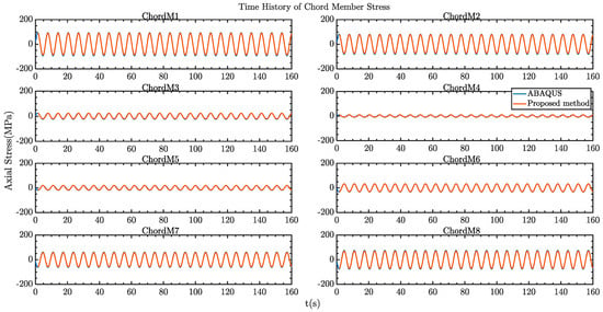
Figure 9.
Comparison of the time history of chord member axial stresses under regular wave excitations.
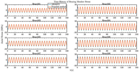
Figure 10.
Comparison of the time history of bracing member axial stresses under regular wave excitations.
4.2. Dynamic Responses in Irregular Waves
The time history motion of the hull centroid in random waves and the corresponding response spectrum from the dynamic analysis based on the proposed methods and full-order FE analysis in ABAQUS are shown in Figure 11. In general, the agreement between the two methods is very good, indicating that the proposed method can well capture the global dynamic responses of the hull. A slight difference can be found between the proposed method and the full-order FE analysis at the resonant range, suspected to be due to the different ways of introducing hydrodynamic damping as explained earlier in Section 4.1. Compared to the surge response under the regular wave excitations, the response in irregular waves tends to be mild, with a maximum value smaller than 0.2 m. From the response spectra, the resonant motion is obviously observed to be dominated by the second structure mode.
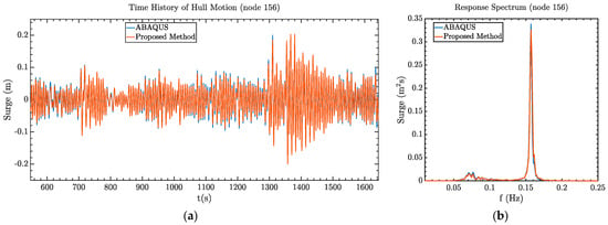
Figure 11.
Comparison of motion time history (a) and the corresponding response spectrum (b) at the hull centroid in surge under irregular wave excitations.
Figure 12 shows the comparison of the nodal displacement at the selected locations along the forward legs, and Figure 13 and Figure 14 show the comparison of axial stresses in the chord and bracing members. The time histories are presented for 160s. Again, the nodal displacements of the forward legs from the two models show very good agreement among each other. The same trend can be found from the comparison of stresses in chord and bracing members. Some differences can be found from the stresses in chord member 4 (see Figure 12). As explained earlier, this could be related the local hydrodynamic effect and the differences in the mode shapes. These are expected to have acceptable influence on the results, considering the presented methods are proposed for efficient analysis of global dynamic responses and stresses for the SEU.
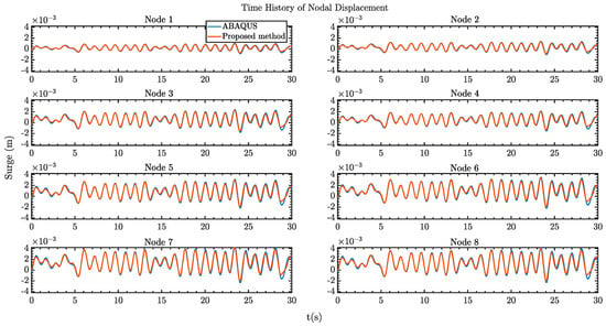
Figure 12.
Comparison of the time history of nodal displacement in surge under irregular wave excitations.
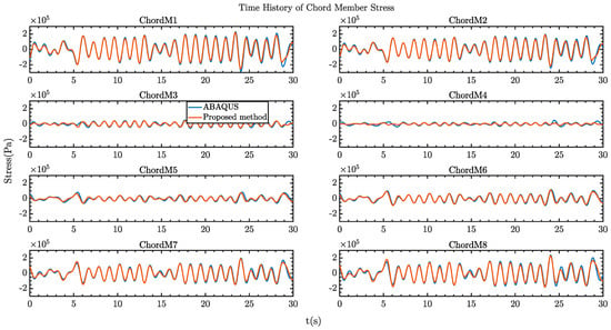
Figure 13.
Comparison of the time history of stresses for chord members along forward leg of the SEU under irregular wave excitations.
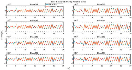
Figure 14.
Comparison of the time history of stresses for bracing members along the forward leg of the SEU under irregular wave excitations.
4.3. Efficiency of the Proposed Method
A comparison of the computational cost for simulating the above-mentioned dynamic analysis in regular and irregular waves is listed in Table 5. The simulations are run on the same personal computer (PC). The computational cost for the simulation with the proposed method includes two major parts, simulation with the stick model and quasi-static analysis in the full-order FE model, and the computational costs for the two parts are separately presented in the table. It can be found that the proposed method is 25–30 times faster than the conventional method. A large portion of the computational time for quasi-static analysis is due to interfacing the output from the stick model, which could be further reduced. In general, the high efficiency makes it a suitable candidate as an engine for the digital twining of SEUs so that it can be used for online model updating and prediction under various environmental conditions.

Table 5.
Comparison of computational cost for the proposed method and direct simulations in ABAQUS.
5. Conclusions
In this paper, a new framework to efficiently calculate dynamic responses and stresses for self-elevating units is developed. The method assumes that a reduced-order stick model can represent the critical dynamic characteristics of the SEU, and thus, the mode shapes are consistent with the full-order FE model. Based on the assumption, the dynamic responses of the entire SEU can be obtained by multiplying modal participation factors obtained from the dynamic analysis of the stick model with the corresponding mode shapes obtained from the full-order FE model. To perform strength analysis, the obtained nodal displacements are imposed on the full-order FE model.
To verify the proposed framework, a stick model and a detailed FE model of an in-house developed generic SEU are established. The global responses and member stresses obtained from the proposed method are rigorously compared with those from the direct full-order dynamic FE analysis for both regular waves and irregular waves. It is found that the presented framework can significantly increase the efficiency of the simulation while maintaining acceptable accuracy. The computational cost for the proposed method is 25 to 30 times faster than the conventional method. The significant improvement in the efficiency makes the proposed framework a suitable solution for the development of digital twins of fixed offshore structures.
It should be noted that the presented method is unable to handle strong non-linear behavior, such as spudcan–soil interactions. However, it can provide predictions of the dynamic responses of SEUs with vastly reduced requirements on computational resources, therefore rendering it suitable for timely decision making and intervention. Future work will include benchmarking the proposed method with the results from model tests conducted in the TCOMS ocean basin and extending the method to account for the effect of current and relative velocities.
Author Contributions
Conceptualization, C.Z., S.Z., C.Z. and S.Z.; software, M.Y. and M.C.; validation, S.Z., M.Y. and M.C.; formal analysis, C.Z.; investigation, C.Z.; resources, H.S. and S.Z.; data curation, C.Z.; writing—original draft preparation, C.Z., H.S. and S.Z.; writing—review and editing, C.Z., S.Z. and H.S.; visualization, C.Z. and S.Z.; supervision, H.S. and M.S.; project administration, M.S.; funding acquisition, M.S. All authors have read and agreed to the published version of the manuscript.
Funding
RIE 2020 Industry Alignment Fund (Grant No: A19F1a0104) by A*STAR.
Institutional Review Board Statement
Not applicable.
Informed Consent Statement
Not applicable.
Data Availability Statement
Not applicable.
Acknowledgments
The work presented in this paper is a result of the research effort through the Enhancing Offshore System Productivity, Integrity and Survivability in Extreme Environments (ENSURE) program financed by A*STAR under its RIE 2020 Industry Alignment Fund (Grant No: A19F1a0104).
Conflicts of Interest
The authors declare no conflict of interest.
References
- Ahmed, K.S.; Keng, A.K.; Ghee, K.C. Stress and stiffness analysis of a 7-teeth pinion/rack jacking system of an Offshore jack-up rig. Eng. Fail. Anal. 2020, 115, 104623. [Google Scholar] [CrossRef]
- American Bureau of Shipping. Guidance Notes on Dynamic Analysis Procedure for Self-Elevating Drilling Units; American Bureau of Shipping: Houston, TX, USA, 2004. [Google Scholar]
- Det Norske Veritas. Self-Elevating Units; Report No. DNV-RP-C104; DNV: Høvik, Norway, 2012. [Google Scholar]
- SNAME, H. Guidelines for Site Specific Assessment of Mobile Jack-Up Units; T&R Bulletin 5-5A; Society of Naval Architects and Marine Engineers: Jersey City, NJ, USA, 2008; p. 366. [Google Scholar]
- Kulovic, N.; Offshore Energy. Velesto Rig Working for ConocoPhillips Sinks off Malaysia. Available online: https://www.offshore-energy.biz/velesto-rig-working-for-conocophillips-sinks-off-malaysia/ (accessed on 4 May 2021).
- Buljan, A.; Slat, B.; Offshorewind. Four Missing After Jack-Up Vessel Tilts at Offshore Wind Farm in China. Available online: https://www.offshorewind.biz/2021/07/26/four-missing-after-jack-up-vessel-tilts-at-offshore-wind-farm-in-china/ (accessed on 26 July 2021).
- Bonaldo, D.; Bucchignani, E.; Pomaro, A.; Ricchi, A.; Sclavo, M.; Carniel, S. Wind waves in the Adriatic Sea under a severe climate change scenario and implications for the coasts. Int. J. Climatol. 2020, 40, 5389–5406. [Google Scholar] [CrossRef]
- Jiang, Z. Installation of offshore wind turbines: A technical review. Renew. Sustain. Energy Rev. 2021, 139, 110576. [Google Scholar] [CrossRef]
- Zhao, Y.; Cheng, Z.; Sandvik, P.C.; Gao, Z.; Moan, T.; Van Buren, E. Numerical modeling and analysis of the dynamic motion response of an offshore wind turbine blade during installation by a jack-up crane vessel. Ocean. Eng. 2018, 165, 353–364. [Google Scholar] [CrossRef]
- Augener, P.H.; Hatecke, H. Sea-keeping analysis of an offshore wind farm installation vessel during the jack-up process. In Proceedings of the ASME 2014 33rd International Conference on Ocean, Offshore and Arctic Engineering, San Francisco, CA, USA, 8–13 June 2014; American Society of Mechanical Engineers: New York, NY, USA, 2014; Volume 45370, p. V01AT01A031. [Google Scholar]
- Taylor, P.H.; Jonathan, P.; Harland, L.A. Time domain simulation of jack-up dynamics with the extremes of a Gaussian process. J. Vib. Acoust. 1997, 119, 624–628. [Google Scholar] [CrossRef]
- Williams, M.S.; Thompson, R.S.; Houlsby, G.T. Non-linear dynamic analysis of offshore jack-up units. Comput. Struct. 1998, 69, 171–180. [Google Scholar] [CrossRef]
- Ghazi, Z.M.; Abbood, I.S.; Hejazi, F. Dynamic evaluation of jack-up platform structure under wave, wind, earthquake and tsunami loads. J. Ocean. Eng. Sci. 2022, 7, 41–57. [Google Scholar] [CrossRef]
- Bienen, B.; Cassidy, M.J. Advances in the three-dimensional fluid–structure–soil interaction analysis of offshore jack-up structures. Mar. Struct. 2006, 19, 110–140. [Google Scholar] [CrossRef]
- Cho, T.M.; Park, J.S.; Ha, Y.S.; Kim, B.J.; Jang, K.B. Global In-Place Analysis of WTIV Leg for Korean West-South Offshore Wind Zone. In Proceedings of the Twenty-Fourth International Ocean and Polar Engineering Conference, Busan, Korea, 15–20 June 2014; OnePetro: Richardson, TX, USA, 2014. [Google Scholar]
- Zhang, C.; Santo, H.; Cai, M.; Magee, A. Dynamic response of a generic self-elevating unit in operation with hull in water. In Proceedings of the ASME 2022 42nd International Conference on Ocean, Offshore and Arctic Engineering, Melbourne, Australia, 11–16 June 2023. [Google Scholar]
- Liu, L.; Yang, J.; Tian, X.; Lu, H.; Li, C.; Yuan, H. Experimental investigation on the hydrodynamic performance of a quay moored jackup. Ships Offshore Struct. 2017, 12, 679–689. [Google Scholar] [CrossRef]
- Liu, P.; Massie, W.W.; Wolters, J.G.; Blaauwendraad, J. Response of jackup models to irregular waves. In Proceedings of the Offshore Technology Conference, Houston, TX, USA, 6–9 May 1991; OnePetro: Richardson, TX, USA, 1991. [Google Scholar]
- Mirzadeh, J.; Kimiaei, M.; Cassidy, M.J. Performance of an example jack-up platform under directional random ocean waves. Appl. Ocean. Res. 2016, 54, 87–100. [Google Scholar] [CrossRef]
- Shabakhty, N. Durable Reliability of Jack-Up Platforms. Ph.D. Thesis, Universiteit Delft, Delft, The Netherlands, 2004. [Google Scholar]
- Yu, H.; Li, X.; Yang, S. Dynamic analysis method of offshore jack-up platforms in regular and random waves. J. Mar. Sci. Appl. 2012, 11, 111–118. [Google Scholar] [CrossRef]
- Standing, R.G.; Towe, S.J. Stability and seakeeping review for jack-ups in transit. In Proceedings of the 4th International Conference on the Jack-Up Platform, London, UK, 21–22 September 1993. [Google Scholar]
- Standing, R.G.; Jackson, G.E.; van Santen, J.A.; Mills, P.J.; Barltrop, N.D. Investigations into the stability of an intact and damaged jack-up during a wet tow. Part 1: The model test programme. Mar. Struct. 2001, 14, 417–430. [Google Scholar] [CrossRef]
- van Santen, J. Jack-up model tests for dynamic effects on intact and damaged stability. Mar. Struct. 2001, 14, 431–449. [Google Scholar] [CrossRef]
- Kang, W.H.; Zhang, C.; Yu, J.X. Stochastic extreme motion analysis of jack-up responses during wet towing. Ocean. Eng. 2016, 111, 56–66. [Google Scholar] [CrossRef]
- Weihrauch, A.; Berger, J.; Bartels, M. Ice loading of jack-up platforms. In Proceedings of the 24th International Conference on Offshore Mechanics and Arctic Engineering, Halkidiki, Greece, 12–17 June 2005; Volume 41960, pp. 913–917. [Google Scholar]
- Mehlan, F.C.; Nejad, A.R.; Gao, Z. Digital twin based virtual sensor for online fatigue damage monitoring in offshore wind turbine drivetrains. J. Offshore Mech. Arct. Eng. 2022, 144, 060901. [Google Scholar] [CrossRef]
- Sireta, F.X.; Van der Cammen, J.; Storhaug, G. Aoka Mizu FPSO Hybrid Twin Pilot-A Spectral Approach for Holistic Hull Structure Monitoring from Strain Gauges Measurements and Structural Analysis. In Proceedings of the Offshore Technology Conference, Houston, TX, USA, 2–5 May 2022; OnePetro: Richardson, TX, USA, 2022. [Google Scholar]
- Zhang, X.Y.; Cheng, Z.P.; Wu, J.F.; Kei, C.C. Dynamic response of Jack-up units—Reevaluation of SNAME 5-5A four methods. In Proceedings of the Twentieth International Offshore and Polar Engineering Conference, Beijing, China, 20–25 June 2010; OnePetro: Richardson, TX, USA, 2010. [Google Scholar]
- Abaqus, G. Abaqus 6.11; Dassault Systemes Simulia Corporation: Providence, RI, USA, 2011. [Google Scholar]
- Dooms, D.; Jansen, M.; De Roeck, G.; Degrande, G.; Lombaert, G.; Schevenels, M.; François, S. StaBIL: A Finite Element Toolbox for MATLAB; VERSION 2.0 USER’S GUIDE; Katholieke Universiteit Leuven: Leuven, Belgium, 2014. [Google Scholar]
- Morison, J.R.; O’Brien, M.P.; Johnson, J.W.; Schaaf, S.A. The force exerted by surface waves on piles. J. Pet. Technol. 1950, 189, 149–154. [Google Scholar] [CrossRef]
Disclaimer/Publisher’s Note: The statements, opinions and data contained in all publications are solely those of the individual author(s) and contributor(s) and not of MDPI and/or the editor(s). MDPI and/or the editor(s) disclaim responsibility for any injury to people or property resulting from any ideas, methods, instructions or products referred to in the content. |
© 2023 by the authors. Licensee MDPI, Basel, Switzerland. This article is an open access article distributed under the terms and conditions of the Creative Commons Attribution (CC BY) license (https://creativecommons.org/licenses/by/4.0/).