Abstract
To address the problems of high digging resistance, elevated energy consumption, and severe soil adhesion encountered during mechanized potato harvesting, a bionic potato digging shovel inspired by the corrugated dorsal structure of the white grub was developed. Based on reverse-engineered geometric curves, two longitudinally corrugated shovel models (L-S-1 and L-S-2) were constructed, and a coupled soil–potato–shovel model was established using the Discrete Element Method (DEM) to evaluate soil disturbance characteristics and digging resistance at a forward speed of 0.5 m/s and an entry angle of 35°. The simulation results indicated that the longitudinally corrugated shovel L-S-2 exhibited the best overall performance, reducing digging resistance by 13.87% and increasing the soil fragmentation rate by 20.67% compared with a conventional flat shovel (P-S). Using L-S-2 as the baseline design, additional DEM simulations were conducted at forward speeds ranging from 0.4 to 0.6 m/s to systematically investigate the influence of operating speed on digging performance. To further enhance anti-adhesion performance, a composite bionic shovel (H-L-S-2) was developed by embedding polytetrafluoroethylene (PTFE) hydrophobic material into the surface of L-S-2 and reinforcing the shovel tip using laser cladding. Soil-bin experiments were then performed under controlled conditions with forward speeds of 0.4–0.6 m/s and soil moisture contents of 15–20% at an entry angle of 35°, and the results showed an average resistance reduction rate of 17.46%, with a maximum reduction of 18.02%. Both DEM simulations and soil-bin tests confirmed the effectiveness of the composite bionic shovel in reducing soil adhesion, with the number of adhered soil particles decreasing by 41.2% in simulations and the mass of adhered soil reduced by 37.5% in physical tests. These results demonstrate that coupling a bionic corrugated structure with surface material modification can effectively reduce digging resistance, enhance soil fragmentation, and mitigate soil adhesion, providing a practical approach for optimizing the design of potato digging shovels.
1. Introduction
The potato (Solanum tuberosum L.) originated in the Andean Highlands of South America and has been cultivated for approximately 8000–10,000 years; it is currently the fourth most important staple crop worldwide [1]. Its tubers are rich in carbohydrates, dietary fiber, and vitamin C, and are widely used in food processing and industrial applications. Global potato production reached approximately 383 million tons in 2023, with China accounting for about 25% (93.49 million tons), followed by India at approximately 15% (60.14 million tons); Asia as a whole contributes more than half of global production [2]. As the proportion of potato planting continues to increase, improving harvesting efficiency and reducing yield losses have become critical research objectives. As a core component, the potato digger shovel often encounters high digging resistance and elevated energy consumption during operation. Most existing potato digging shovels adopt flat blade structures, which are prone to soil accumulation and adhesion under cohesive soil conditions, thereby limiting harvesting efficiency. Currently, the main methods for reducing resistance in potato digging include vibration reduction and structural optimization reduction [3,4], but vibration reduction still has issues such as high energy consumption and complex mechanical structure. Consequently, achieving efficient potato harvesting while simultaneously reducing digging resistance and soil adhesion places increasing demands on the design and mechanization level of digging shovels. In this context, bionic design combined with discrete element method (DEM) analysis has emerged as an effective approach for improving soil–tool interaction and reducing resistance in agricultural machinery.
In recent years, with the development of discrete element simulation technology, an increasing number of researchers have applied this method to soil model development, material parameter calibration, working mechanism research, and soil disturbance analysis [4,5]. In the field of bionic research, many studies have shown that soil-dwelling animals, such as earthworms [6], sharks [7], and pangolins [8], experience relatively low digging resistance during movement. Incorporating the structural characteristics of these animals into the design of soil-contact components can effectively reduce digging resistance and achieve resistance reduction [9]. For heavy clay black soil conditions, a potato digging shovel with a bionic corrugated structure was designed, and comparative experiments including discrete element simulations, soil bin tests, and field trials verified its improved performance in reducing soil adhesion and digging resistance [10]. To address problems such as high digging resistance and low root–soil separation efficiency during the mechanized harvesting of Panax notoginseng, a bionic digging shovel inspired by the snout structure of wild boars was developed. EDEM simulation results and soil bin tests confirmed that the bionic curved surface structure effectively mitigates soil bulging and reduces digging resistance [11]. Inspired by pangolin scales, a bionic digging shovel with soil adhesion and digging resistance reduction capabilities was designed by applying bionic treatment to the surface of a potato digging shovel, and comparative tests demonstrated that this bionic digging shovel achieved lower soil adhesion and digging resistance than conventional designs [12]. Previous studies have shown that the claw structure of the mole rat exhibits high strength, sharp edges, and excellent adaptability to soil excavation [13,14]. Based on an in-depth analysis of the combined characteristics of the toe claws of mole forepaws, a bionic rotary tiller blade was designed, and field tests showed that the operating power consumption of this blade was significantly reduced, exhibiting an evident resistance reduction effect [15]. In addition, a bionic subsoiler was developed using the largest toe of the mole cricket foreleg as the bionic prototype, and experimental results indicated that the horizontal and vertical tillage forces were reduced by 16.34% and 24.53%, respectively, while energy consumption was reduced by 9.64% [16]. Furthermore, a bionic coupled disc furrow opener was designed using the convex protrusions on the pronotum of dung beetles and the dorsal scales of pangolins as bionic prototypes. Discrete element simulations showed that this furrow opener significantly reduced digging resistance, achieving a maximum resistance reduction of 45.4% under optimal parameters; soil bin tests further verified its resistance reduction performance, with an average reduction rate of 8.8% under different operating speeds and soil moisture conditions, while also causing less soil disturbance [17]. Overall, most reported bionic designs reduce soil adhesion and friction by introducing non-smooth surface geometries (e.g., convex, concave, or scale-like structures) to modify soil–tool interaction and stress distribution. For example, mole-inspired claw structures enhance cutting efficiency through stress concentration, whereas pangolin-scale-inspired surfaces promote soil detachment. In contrast, white grub larvae interact with soil through continuous corrugated dorsal surfaces that guide soil flow, suppress stagnation, and reduce rear-side compaction, a flow-regulating mechanism well suited to the continuous cutting and lifting processes of potato digging shovels, which motivated the selection of the white grub as the bionic prototype in this study.
Incorporating composite materials into the bionic structures of soil-contact components in agricultural machinery can enhance wear resistance, improve anti-adhesion performance, and reduce digging resistance, thereby increasing operational efficiency and extending service life. Using the non-smooth convex structures on the body surface of dung beetles as the bionic prototype, a series of bionic resistance-reducing plates were developed by integrating ultra-high molecular weight polyethylene (UHMW-PE). Experimental results demonstrated that the combined application of bionic structural design and composite materials significantly improves soil–tool interaction and is suitable for resistance reduction and energy-saving applications under high-adhesion soil conditions [18]. Similarly, taking the head of the northwest zokor as the bionic prototype, a composite bionic wedge-shaped digging shovel was designed by incorporating UHMW-PE anti-adhesion material. This shovel was applied to a self-developed potato combine harvester and proved suitable for efficient harvesting operations in small-scale fields in Northwest China [19].
The discrete element method (DEM) is widely applied in agricultural machinery engineering to simulate interactions between soil-engaging components and soil. In this approach, soil is represented as a discrete system composed of numerous particles, which enables detailed simulation of soil particle motion, contact mechanical behavior, and interaction processes between soil and implements [20,21]. Ucgul et al. developed a DEM model that integrates a linear adhesion–cohesion model with the hysteretic spring contact model (HSCM) to simulate the cohesive behavior of soil and its interaction with tillage tools [22]. Zeng et al. established a discrete element model for soil–tool–residue interaction, which was validated through soil bin experiments and achieved a consistency rate of 93% between simulation and experimental results [23]. This high level of agreement demonstrates the effectiveness of the model in representing complex agricultural interaction processes and provides reliable data support for optimizing tillage tool design and residue management strategies. In addition, Aikins et al. conducted DEM-based modeling and simulation of the operational processes of bent-leg furrow openers with multiple configurations in cohesive soils. Their study systematically analyzed the effects of opener geometric parameters on soil fragmentation behavior and digging resistance characteristics, providing theoretical foundations and data support for the parametric design of soil-engaging tools under clay-rich soil conditions [24].
In summary, this study takes the white grub as the bionic prototype. Based on the corrugated features of its dorsal surface, geometric curve parameters were extracted through reverse engineering to construct two sinusoidally corrugated bionic potato digging shovel models for discrete element simulations. On this basis, the longitudinally corrugated shovel with the best comprehensive performance (L-S-2) was selected and further modified by embedding hydrophobic polytetrafluoroethylene (PTFE) material into the shovel surface and applying laser cladding treatment to the shovel tip, thereby forming a composite bionic digging shovel (H-L-S-2). In contrast to previous studies that addressed structural bionic optimization and surface material modification independently, this study develops an integrated structural–material bionic design framework that combines corrugated surface morphology with hydrophobic functional materials. Furthermore, a soil–potato–shovel coupled DEM model was established and systematically validated through soil-bin experiments under multiple operating conditions, thereby enabling a comprehensive evaluation of resistance reduction, soil fragmentation, soil disturbance, and adhesion mitigation mechanisms.
2. Materials and Methods
2.1. Design of Biomimetic Potato Digging Shovel
The white grub, which is the larval stage of scarab beetles, is a subterranean developmental form of coleopteran insects. Through long-term evolutionary adaptation to soil environments, white grub larvae have developed distinctive morphological and functional characteristics that enable effective reduction of soil adhesion and digging resistance during movement [25]. These characteristics are mainly reflected in their low-friction and low-adhesion surface properties. A typical white grub larva is approximately 5 cm in length and 1 cm in width. The bionic structure of the potato digging shovel in this study is derived from the wave-like morphology on the dorsal surface of the larva. The dorsal surface generally exhibits about 10 wave-like corrugated structures, each with a width ranging from 3 to 6 mm.
The three-dimensional reverse scanning was conducted on 11 April 2025, at the 3D Scanning Laboratory in the Mechanical Training Center of Gansu Agricultural University, Lanzhou City, Gansu Province. The scanning was performed using a high-precision FARO Quantum S Max ScanArm (Model: FaroArm). This scanner has a volumetric accuracy of up to 0.028 mm and a single-point repeatability of 0.018 mm, ensuring high-fidelity capture of the larva’s micro-geometry. Under normal conditions, the body forms a C-shape, and it moves by crawling with its back against the ground, as shown in Figure 1b. Using reverse engineering, the wave-like structure on the back of the larva was extracted. The larva’s surface was cleaned to maintain its slightly curved C-shape, which maximized the expression of the wave structures. A high-precision 3D laser scanner from FARO, combined with Geomagic Wrap, was used to perform a 360-degree scan of the larva’s entire body to obtain point cloud data, as shown in Figure 1c. This data was edited in Geomagic Wrap by removing disconnected points, isolated external points, and applying noise reduction. Afterward, the surface was sealed, as shown in Figure 1d. The sealed surface was filled for any holes, smoothed, and polished before being saved in STL format for further processing. The STL file was imported into Geomagic Design X for editing, where the surface was divided into domains and fitted with patches. Any deficiencies were optimized, and after confirming the absence of errors with the Accuracy Analyzer, the STL surface model was converted into an IGS format model in UG NX 2412 via the real-time conversion function in Geomagic Design X. The wave structure parameters of the larva’s back were extracted, and the wave structure’s cross-sectional curve was obtained by slicing the model in UG NX 2412. As shown in Figure 1e, the cross-sectional curve was input into Caxa for sequential point extraction and coordinate data measurement. The two wave-like curves in the middle part of the structure, which were relatively regular and smooth, were selected, as shown in Figure 1f. These coordinate data were then fitted into wave curves using MATLAB (R2023b), as shown in Figure 1g. The raw coordinate arrays were obtained by extracting sequential points along the curve profile in Caxa with a fixed discretization step of 0.1 mm. To minimize noise from the scanning and point extraction process, a Savitzky Golay filter (polynomial order: 3, frame size: 11) was applied to the raw data before fitting. The fitting process utilized the nonlinear least-squares method to fit the data to a sinusoidal function.
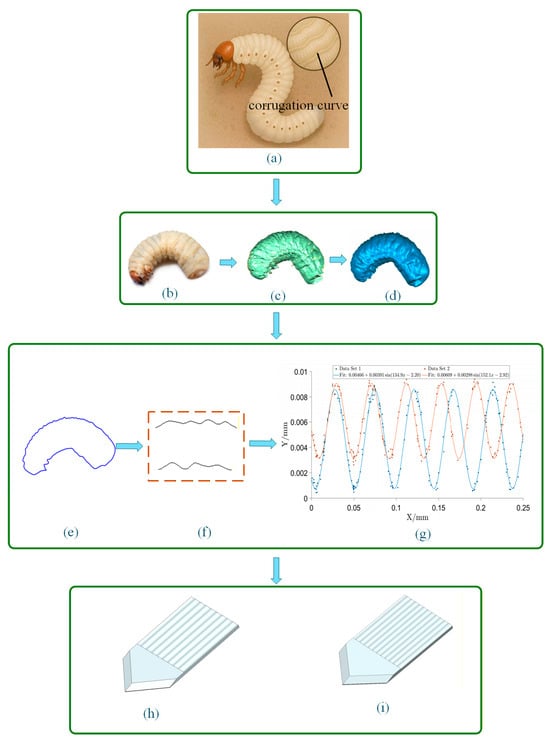
Figure 1.
Flowchart of bionic digging shovel design. (a) Larval body surface wave curve; (b) Larval prototype; (c) Point cloud image; (d) Solid encapsulation image; (e) Wave curve profile; (f) Extracted wave curve profile; (g) Fitted and extracted wave curve; (h) Bionic digging shovel I (L-S-1); (i) Bionic digging shovel II (L-S-2).
The fitted wave curve equations are as follows:
where y1 represents wave curve 1, and y2 represents wave curve 2. The regression coefficients R2 of the fitted wave curve equations are both greater than 0.99, indicating a high degree of fit, which enhances the reliability of the biomimetic curve’s application.
Based on the parameters of the fitted wave curves mentioned above, the fitted curve equations were directly imported into UG NX 2412 software. The scaling factor was determined based on geometric similarity and practical structural constraints of the digging shovel. Considering the overall blade thickness (10 mm), operational strength requirements, and manufacturing feasibility, the crest height of the shovel wave section was set to 2.5 mm, as also referenced in previous studies on biomimetic digging shovel [12]. To ensure the shovel tip maintains sufficient strength, no wave structure was applied to the tip. The directly created wave structure was scaled according to the wave crest ratio, following the scaling rule in Formula 1, ensuring that the biomimetic potato digging shovel has the same profile dimensions as a flat potato digging shovel. Based on the previously mentioned potato planting practices, a 3D model was constructed in UG NX 2412 using the fitted wave curve equations and key parameters (amplitude and period).
where P0 and P1() denote the coordinate points of the biomimetic ripple profile prior to and subsequent to scaling, respectively; The set P0 was derived by extracting the intrinsic biological ripple morphology and performing a curve fit in MATLAB to obtain a high-resolution parametric representation; the scalar coefficient 2.5 is adopted as a dimensionless amplification factor, selected in accordance with precedent in the relevant literature and the specific amplitude requirements of the shovel design; P2 represents the peak value of the wave before scaling; The subscripts n and m index the corresponding coordinate points in the original and scaled datasets, respectively; when m = n, the scaled profile maintains a one-to-one correspondence with the original profile in terms of point indices.
Figure 2a shows the analysis of the structural parameter design of the digging shovel. The calculation formula for the length (L1) of the digging shovel is as follows:
Among them, (H) refers to the installation height of the digging shovel’s end, in millimeters (mm); (β) refers to the installation angle of the digging shovel, in degrees (°).
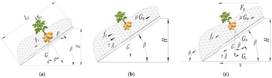
Figure 2.
Force Analysis on the Blade of a Digging Shovel. (a) Analysis on structural parameter design of the digging shovel; (b) Free-body diagram of the digging shovel-soil interaction; (c) Force analysis of mixture on the digging shovel.
During the harvesting process, the digging resistance is jointly influenced by factors such as soil type, digging depth, shovel type, and installation angle, and its calculation formula is as follows:
Among them: (F) is the force required to lift the digging shovel, in newtons (N); (Fr) is the frictional resistance of the digging shovel, in newtons (N); (G) is the gravity of the soil on the digging shovel surface, in newtons (N); (Nr) is the reaction force of the soil on the digging shovel, in newtons (N); (β) refers to the installation angle of the digging shovel, in degrees (°); (μm) is the friction coefficient between the soil and the digging shovel.
By solving the above equations simultaneously, the angle of the digging shovel can be obtained as follows:
As shown in Figure 1h,i, the two bionic excavating shovels L-S-1 and L-S-2 are both designed based on the dorsal ripple curve of the white grub, but adopt different fitting curve equations. L-S-1 (Figure 1h) is based on the ripple curve y1, with a higher ripple density; L-S-2 (Figure 1i) is based on the ripple curve y2, with a slightly larger ripple amplitude and a slightly longer period. The digging shovel is made of 65Mn steel, and its height is constrained by the structural specifications of the grid rollers and shovel support of the potato harvester, with the designed height H set to 172 mm. Relevant literature indicates that an excessively long digging shovel is prone to soil blockage. Thus, the designed overall dimensions of the bionic potato digging shovel in this study are 300 mm × 154 mm × 10 mm (length × width × thickness). To ensure the self-cleaning performance of the shovel edge, its cutting edge angle is designed to be 95°. The inclination angle β in Equation (7) is derived from the force equilibrium of the shovel–soil system under steady operating conditions. During the derivation, it is assumed that the friction coefficient between the soil and the shovel, as well as the gravitational load acting on the shovel surface, remain constant under a given working condition. Therefore, Equation (7) describes a theoretical equilibrium relationship between the acting forces and the shovel inclination angle, which provides a basis for determining a reasonable design range of β.
To explore the sources of resistance encountered by the potato digging shovel during operation, this paper proposes a mechanical model describing the interaction between the shovel and the material. The model aims to analyze the various forces acting on the shovel surface during the process of cutting into and lifting potatoes, and to derive the mathematical expression for the total resistance. Figure 2b shows the force diagram of the proposed model.
The lateral mechanical equilibrium equation of the digging shovel is derived from Figure 2b:
Among them: (F0) is the total resistance of the digging shovel during operation (N); (G) is the gravity of the material above the shovel surface (N); (τ) is the material adhesion force (Pa), The adhesion stress (τ) (Pa) represents the shear strength required to separate soil from the shovel surface. Its value is influenced by soil moisture, clay content, and metal properties. For the purpose of this conceptual model, (τ) is treated as a lumped parameter characterizing adhesion; (A) is the effective contact area between the shovel surface and the soil (m2); (fc) is the pure cutting resistance (N); (μ) is the soil internal friction coefficient; (β) is the shovel surface inclination angle (°).
As shown in Figure 2c, the force balance equation in the horizontal direction can be expressed as:
Among them: (Gn) is the normal load on the digging shovel, in newtons (N); (Gt) is the transverse load on the digging shovel, in newtons (N); (θ) is the angle of the front failure surface, in degrees (°).
The vertical force on the material above the shovel surface is analyzed, and the force balance equation in the vertical direction is derived as follows:
Among them, all physical quantities in Equation (10) have been previously defined in Equations (8) and (9).
By solving Equations (8)–(10) simultaneously, the resistance of the digging shovel when moving in soil is obtained as follows:
Among them: (μm) is the friction coefficient of the soil on the digging shovel; (C) is the comprehensive coefficient.
Equations (11) and (12) propose a simplified analytical model for the total resistance (F0), which includes gravity, adhesion, cutting force, and friction. The angles (θ) (failure surface angle) and (β) (entry angle) are key geometric parameters. Analyzing the partial derivatives ∂F0/∂θ and ∂F0/∂β in Equation (13) can reveal theoretical trends. By deriving the derivative of the resistance (F0), the following is obtained:
By taking the partial derivatives of the digging resistance F0 with respect to β and θ, as shown in Equation (13), the resistance reaches an extremum when cos β − μsin β = 0 and cos θ − μsin θ = 0. This result indicates that the digging resistance tends to decrease as β and θ approach 45°, corresponding to a theoretical optimal condition derived from the analytical model. However, in actual potato harvesting operations, the entry angle of the shovel cannot be dynamically adjusted, and must comply with agronomic requirements and the structural constraints of the harvester. Therefore, taking into account practical field operating conditions in Gansu Province of Northwest China—such as ensuring smooth material flow over the shovel surface—and considering that the digging shovels installed on potato harvesters in this region are generally set at 35° (with an adjustable range of ±5°) [26], the soil entry angle of the potato digging shovel is finally set to 35° since the digging entry angle is not adopted as an experimental factor in this study.
To experimentally calibrate the key parameters in the theoretical resistance model (Equations (11) and (12)), this study used a ZJ-2 strain-controlled direct shear apparatus to measure the internal friction angle (ω) and cohesion (ψ) of the tested soil (collected from Dingxi, Gansu Province) with a soil moisture content of 16.11%. The direct shear test is shown in Figure 3a. During the test, the soil sample was placed in the soil shear box, and a certain vertical pressure (100, 200, 300 kPa) was applied on it. The lower box of the shear box was fixed, and a horizontal force was applied to the upper shear box, which moved horizontally relative to the lower box at a speed of 1 mm/s. Shear stress was applied on the horizontal cross-section of the soil sample. When the shear stress exceeded a certain value, the soil sample was sheared, and the shear stress at this time was called the shear strength of the soil. Each group was repeated three times. When measuring the interaction between soil and the shovel, the lower part of the soil was replaced with a 65Mn steel plate. The soil shear strength is caused by soil cohesion and internal friction. The friction angle and cohesion between soil particles can be calculated by Equation (14):
where η is the shear strength in kPa; σ is the vertical pressure in kPa; ω is the friction angle in (°); ψ is the cohesion in kPa.
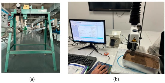
Figure 3.
Experimental Calibration of Key Parameters in the Theoretical Resistance Model. (a) Soil direct shear test; (b) Determination of the adhesion force of soil to 65Mn.
According to the strength theory, the internal friction coefficient of the soil was calculated as μ = tan(ω) = 0.53, and the cohesion ψ = 4.01 kPa. The friction coefficient (μm) between the soil and the shovel material (65Mn steel) was determined by a sliding friction test, and the result was 0.32.
The adhesion stress per unit area (τ) of the soil to 65Mn steel was measured using a Stable Micro Systems texture analyzer (Figure 3b). The device mainly consists of a fixed bracket, a tension sensor (with a data accuracy of 0.0001 N and a maximum range of 500 N), a rectangular sample box (50 mm × 150 mm), a cylindrical test piece (36 mm in diameter × 40 mm in height), and a manual lifting mechanism. The tested soil was sieved through a 2 mm sieve, adjusted to the target moisture content of 16%, and sealed for 24 h. The soil sample was filled into the sample box and slightly scraped flat to ensure full contact between the soil and the surface of the 65Mn steel. During the test, the cylindrical test piece was pressed into the soil to a depth of 40 mm, then the sample box was vertically pulled up at a constant rate of 2 mm/min, and the curve was recorded by the tension sensor. The peak tension in the curve was taken as the adhesion force. The test was conducted three times, and the adhesion forces were 1.42 kPa, 1.51 kPa, and 1.63 kPa, with an average of 1.52 kPa and a standard deviation of 0.1054 kPa. By substituting the above measured parameters into Equations (11) and (12), the theoretical estimation of the excavation resistance can be performed. The average error between the estimated results and the measured values from the soil tank test is less than 8%, which verifies the rationality of the theoretical model and the accuracy of the parameters.
2.2. DEM Simulation
The discrete element simulations were conducted on 4 May 2025, and data post-processing was completed on 29 June 2025, both at Gansu Agricultural University, Lanzhou, Gansu Province, China. The potato digging process was simulated using the Discrete Element Method (DEM), and the simulation workflow of the bionic potato digging shovel is illustrated in Figure 4. The geometric models of the two bionic digging shovels were created using UG NX 2412 software, converted into STL format, and imported into EDEM 2022 for discrete element simulations. Simulation results were evaluated using soil particle velocity fields, soil disturbance characteristics, digging resistance, and soil fragmentation as performance indicators. The resistance reduction performance of the two bionic shovels was analyzed and compared with that of a conventional flat shovel to identify the optimal design for subsequent physical testing.
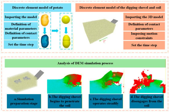
Figure 4.
Discrete element simulation flowchart.
The shape of potato tubers is influenced by internal growth processes and external environmental conditions, resulting in considerable morphological variability at maturity. As shown in Figure 5, reverse modeling was performed by three-dimensional scanning of potato tubers to establish their geometric model. The Hertz–Mindlin with Bonding contact model was employed to construct bonded particle assemblies within the potato model, enabling a realistic representation of the mechanical interaction between potato tubers and soil during the harvesting process. Simulation parameters were determined based on relevant literature, and the specific values are listed in Table 1 [27,28,29].
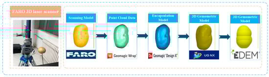
Figure 5.
Potato discrete element model.

Table 1.
Parameters of potato discrete element model.
Three-dimensional laser scanning was employed to acquire the surface geometric information of representative tubers. Based on point cloud data processing, a multi-sphere aggregation model was developed in EDEM using the multi-sphere filling algorithm. Each potato tuber was represented as an aggregate composed of 13 overlapping spheres, with sphere radii ranging from 10.49 mm to 21.87 mm. The positions and radii of the spheres were automatically optimized to minimize the volumetric error between the aggregate model and the scanned geometry.
All simulation tests were conducted using EDEM 2022. To improve computational efficiency, a simplified configuration was adopted by using a single digging shovel blade in the simulations. A discrete element soil bin was constructed to contain the soil particles, with dimensions of 500 mm × 400 mm × 300 mm (length × width × height). The soil bin width (400 mm) was more than twice the shovel width (172 mm), ensuring that the lateral boundaries were located outside the primary soil disturbance zone generated during digging. Furthermore, the discrete element simulation results indicated that the soil disturbance width was significantly smaller than the bin width, with the disturbed region remaining well within the side boundaries. This confirms that lateral constraints did not influence the soil–tool interaction behavior. In addition, the soil depth (300 mm) exceeded the maximum working depth and the observed failure zone, thereby minimizing bottom boundary effects. The potato and digging shovel models were imported into EDEM 2022 in STL format. Based on agronomic requirements for potato cultivation, the potato burial depth (H1) was set to 175 mm. Two potato plants were arranged in the soil bin, with each plant consisting of five potato tubers, and the spacing between plants (D) was set to 300 mm. The digging depth was set to 200 mm. According to typical operating parameters of potato harvesters and considering both agronomic requirements and computational efficiency, the digging shovel entry angle was set to 35°, and a linear translation motion with a forward speed of 0.5 m/s was applied. The total simulation time was set to 3 s. Based on soil conditions in Dingxi City, Gansu Province, where soil moisture content typically ranges from 12% to 20%, the soil exhibits strong adhesion to the digging shovel during harvesting operations. The soil used in both the discrete element simulations and soil-bin experiments was collected from this region. According to laboratory particle size analysis, the soil was classified as clay loam. The particle size distribution consisted of 24.56% clay (<0.001 mm), 58.72% silt (0.001–0.05 mm), and 16.72% sand (0.05–2 mm). The natural bulk density was 1.277 g/cm3. To balance computational efficiency and simulation accuracy, soil particles are simplified as uniform spherical particles with a radius of 2.5 mm. This size is chosen as the equivalent representative particle size commonly used in discrete element method simulations of interactions. By calibrating contact and bonding parameters, the macroscopic mechanical behavior of the soil is ensured, including resistance and disturbance characteristics. Previous studies have shown that properly calibrated equivalent spherical particles can effectively reproduce the overall behavior of interactions.
To verify the applicability of soil parameters adopted from the literature, the angle of repose of the soil was measured experimentally. A bottomless cylindrical tube with an inner diameter of 80 mm and a height of 90 mm was filled with soil and then slowly lifted at a constant speed of 0.1 m/s. After the soil slope stabilized, a vertical image was captured and imported into CAXA 2024 software to calculate the angle of repose. This procedure was repeated five times. In addition, a soil-dropping model was established in EDEM to generate simulated soil with the same mass as the experimental sample. The simulated angle of repose was obtained and compared with the measured value. As shown in Figure 6, the experimental and simulated angles of repose were 29.40° and 28.37°, respectively, corresponding to a relative error of 3.50%. These results indicate that the soil particle model meets the accuracy requirements for discrete element soil bin simulations.
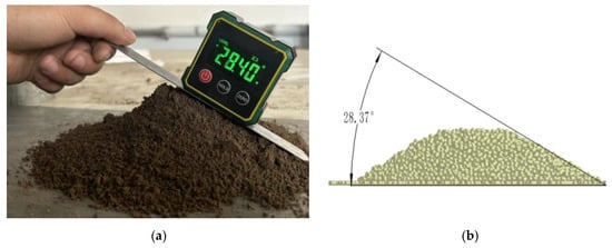
Figure 6.
Soil angle of repose test. (a) physical experiment device; (b) simulation model developed in EDEM.
The material and contact parameters were initially determined based on relevant literature for clay loam soils [16,30,31]. Since the soil used in the present study was also classified as clay loam, these parameters were subsequently calibrated according to the measured physical properties of the Dingxi soil, including particle size distribution, bulk density (1.277 g/cm3) and moisture content. The calibration was performed to ensure that the simulated soil–shovel interaction behavior was consistent with the observed experimental results. The final parameter values used in the simulations are listed in Table 2.
Table 2.
Parameter settings for soil particles and digging components.
The bonding parameters (normal stiffness per unit area, tangential stiffness per unit area, critical normal strength, critical tangential strength, and bonding radius) are determined by considering the soil moisture content (12–20%) and high fine particle content of Dingxi clay loam. These parameters were initially selected based on literature on similar cohesive soils [16,30,32] and then calibrated to ensure that the simulated soil disturbance and resistance behavior were consistent with the observations from the soil tank tests. The final parameter values of the Bonding bonds used in the simulation are listed in Table 3.
Table 3.
Soil particle Bonding bond parameters.
To evaluate the reliability of the DEM model in predicting excavation resistance, a direct comparison was made between the simulated resistance of the traditional flat shovel (P-S) and the measured values from soil bin tests. Before the test, ridges were constructed, and single-row potatoes were buried with the minimum depth of the potatoes being 180 mm and the ridge width being 500 mm. After sprinkling water, the ridges were left to stand to ensure uniform soil moisture content, which was then measured by the oven-drying method to be 16.58%. Subsequently, the excavation depth was adjusted to 200 mm, the forward speed of the soil bin cart was set to 0.5 m/s, and the depth-limiting wheels were adjusted so that the vertical force on the tensile stress sensor was basically zero, making the horizontal traction resistance as representative of the excavation resistance as possible. The test was repeated three times, boundary data were removed, and the horizontal traction resistance data from 1 s to 3 s were selected, with their average resistance calculated and compared with the average resistance of the traditional flat shovel (P-S) in the discrete element method. As shown in Figure 7a, the average horizontal traction resistances of Test 1, Test 2, and Test 3 in the soil bin tests were 981 N, 972 N, and 993 N respectively, with the total average of the three groups of data being 982 N. As shown in Figure 7b, the average excavation resistances of Trial 1, Trial 2, and Trial 3 in the discrete element simulation tests were 956 N, 947 N, and 963 N respectively, with the total average of the three groups of data being 955 N. Through calculation, the deviation was 2.82%, indicating that the constructed discrete element soil bin is relatively close to the actual excavation resistance during operation, and the accuracy of the discrete element parameters can demonstrate the interaction relationship between the excavating shovel and the soil.
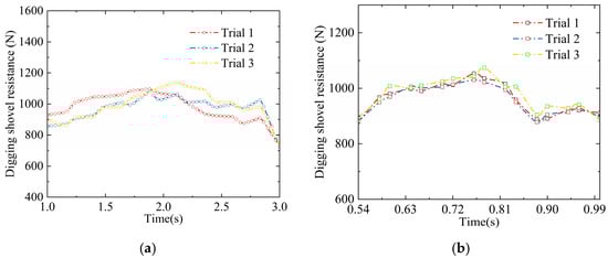
Figure 7.
Comparison and verification between discrete element and actual soil tank. (a) Soil trough test data chart; (b) discrete element test data chart.
2.3. Testing Parameters in the Soil Bin
Based on the discrete element simulation results, the biomimetic corrugated digging shovel with the best overall performance in soil adhesion reduction and digging resistance reduction was selected. To address the soil adhesion problem of the potato digging shovel, a coupling approach combining biomimetic surface reshaping and surface material modification was adopted. In addition to improving anti-adhesion performance, sufficient strength and wear resistance were required due to the high load acting on the shovel tip during operation. The shovel body was fabricated from a 10 mm thick 65Mn steel plate, and the corrugated sections on the shovel surface were embedded with polytetrafluoroethylene (PTFE), an anti-adhesion material. Previous studies have demonstrated that PTFE exhibits excellent resistance reduction performance. To further enhance strength and wear resistance, the shovel tip was treated using laser cladding, in which a layer of iron-based alloy material was fused onto the surface.
Based on the above design, a composite biomimetic digging shovel was manufactured. Soil bin experiments were subsequently conducted in the Electromechanical Laboratory of Gansu Agricultural University, with data acquisition carried out on 25 August 2025. The soil bin testing system consisted of a three-point hitch, data cables, a six-component force telemetry system, a supporting frame, a tension–compression force sensor, the digging shovel, an entry angle adjustment rod, and a depth-limiting wheel. The soil bin testing system and the digging shovel are shown in Figure 8. Prior to the soil bin tests, a large-ridge double-row ridging pattern was prepared in accordance with the agronomic requirements for potato cultivation in the northwestern region of China. During the experiment, the digging depth was adjusted to 200 mm using the depth-limiting wheel. The gravitational load of the experimental setup was fully supported by the depth-limiting wheel, ensuring that the vertical force measured by the sensor was zero, so that the measured horizontal traction force closely represented the digging resistance of the shovel.
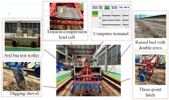
Figure 8.
Soil bin testing system.
During the soil bin tests, the test section was divided into acceleration, working, and deceleration zones, with the acceleration and deceleration zones each set to 0.5 m in length and the working zone set to 1 m. The experimental conditions included operating speeds of 0.4 m/s, 0.5 m/s, and 0.6 m/s, as well as soil moisture contents of 15%, 18%, and 20%, to simulate different operating environments. The soil bin tests were conducted under three speed levels and three soil moisture conditions, and the digging resistance of the biomimetic shovel was measured and compared with that of the conventional flat shovel.
2.4. Evaluation Indices of Digging Performance
Digging resistance is the main factor contributing to the increased energy consumption during potato excavation and is also one of the key indicators for evaluating digging performance. Using the post-processing function of EDEM 2022 software, the resistance during the excavation process can be intuitively extracted and quantified. The quantitative analysis index for this resistance is the average value over one operational cycle. Additionally, the total kinetic energy of all soil particles (including both translational and rotational kinetic energy) can serve as an indirect indicator of the energy consumption of the digging shovel. Its quantitative value is also taken as the average over one operational cycle.
In agricultural machinery research, soil disturbance refers to the displacement, fragmentation, and rearrangement of soil particles during field operations, which are mainly caused by interactions between soil-engaging tools, such as shovels and plows, and the soil. Soil disturbance directly affects soil structure, compaction state, moisture retention capacity, gas exchange, and the root growth environment. Moderate soil disturbance can increase soil porosity and promote water and nutrient transport, whereas excessive disturbance may lead to increased digging resistance [33,34]. Soil bulk density, soil disturbance rate, and soil density change rate are commonly used indicators for evaluating the degree of soil disturbance. Figure 9a illustrates the soil uplift condition on the surface after tillage. The soil bulk density ratio (B) is defined as the ratio of the number of soil particles in the upper soil layer to that in the lower soil layer after excavation.
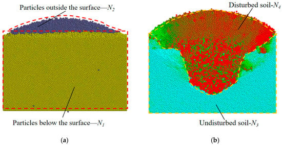
Figure 9.
Valuation indices of digging performance. (a) Graph illustrating the soil bulkiness; (b) Graph illustrating the soil disturbance rate.
The calculation formula is:
where N2 represents the number of soil particles in the upper soil layer of the surface, and N1 represents the number of soil particles in the lower soil layer of the surface.
When the digging shovel causes the maximum disturbance to the soil, it generates a movement velocity of soil particles. By evaluating the internal disturbance profile of the soil, the excavation effect of the biomimetic digging shovel can be compared to that of a regular flat shovel, as shown in Figure 9b. The soil disturbance rate (D) is defined as the ratio of disturbed soil particles to undisturbed soil particles within a specific area. The calculation formula is as follows:
where N4 represents the number of disturbed soil particles, and N3 represents the number of undisturbed soil particles.
Bulk density ratio (B) and disturbance ratio (D) are complementary indicators for quantifying soil structural changes at different scales. The bulk density ratio (B) characterizes the macroscopic displacement and heaving effect of soil in the vertical direction by counting the particle number ratio within specific vertical layers, and a higher B value directly reflects the accumulation degree of surface soil particles after excavation. The disturbance ratio (D), by contrast, measures the spatial extent of soil structural failure and particle rearrangement through identifying the proportion of moving particles in local areas. A higher D value means a larger volume of soil deviates from its original structure with its internal bonding disrupted, which indirectly reflects the improving trend of the soil’s overall looseness and internal pore connectivity.
Soil density change rate is a key indicator for evaluating soil loosening quality. In the experiment, a measuring box was set up to dynamically monitor the number of soil particles in EDEM, and the number of soil particles in the measuring box before and after tillage was collected synchronously. The calculation formula is as follows:
where M1 represents the number of soil particles in the measuring box before the digging operation, and M0 represents the number of soil particles after the digging operation.
In summary, the evaluation indices of digging performance mainly include three categories: Energy consumption indices, including tillage resistance and kinetic energy. Soil disturbance indices, including disturbed soil volume, disturbance rate, and soil density change rate. Soil destruction capacity indices, represented by the number of broken bonds in Bonding. The following will provide both qualitative and quantitative analysis of these digging performance indices.
3. Results and Discussion
3.1. DEM Simulation
3.1.1. Analysis of the Soil Particle Velocity Field
Based on the discrete element simulations of the two bionic corrugated digging shovels, the soil particle velocity fields were extracted and visualized in vector form through post-processing. As shown in Figure 10, soil particle velocity vector diagrams are presented for the conventional flat shovel (P-S) and the two bionic digging shovels (L-S-1 and L-S-2). The arrow directions indicate particle motion directions, while the color scale from cyan to red represents increasing particle velocity. It can be observed that the soil particle velocities near the shovel tips are nearly identical for all three shovel types during the initial soil-cutting stage. However, starting from the corrugated region of the bionic shovels, a greater number of high-velocity soil particles appear in the rear section compared with the flat shovel. This phenomenon indicates enhanced soil flow and fragmentation induced by the corrugated structure during forward motion. In addition, soil particle trajectories exhibit a circular motion toward the shovel handle, allowing soil to detach and fall at higher velocities. This behavior effectively reduces soil accumulation on the shovel surface and lowers digging resistance. In contrast, the rear section of the flat shovel contains fewer high-velocity particles, leading to soil compaction and increased digging resistance. Overall, while soil particle motion on the flat shovel remains relatively uniform, the corrugated surface of the bionic shovels disperses particle motion directions, thereby reducing soil accumulation and resistance.
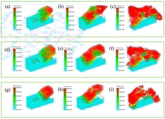
Figure 10.
Soil particle velocity vector diagram. (a,d,g) show the initial soil entry moment for the three types of digging shovels, (b,e,h) represent the stable digging moment, and (c,f,i) depict the soil exit moment for the three types of digging shovels.
Figure 11a shows the variation in soil particle velocity magnitude over time during the simulation. Because the digging shovels move forward at a constant speed and the soil particles are initially stationary, the overall surface particle velocities are similar for both bionic and flat shovels. However, due to the corrugated surface structure, the bionic shovels enhance soil particle flowability, resulting in higher peak particle velocities than those observed for the flat shovel. This effect is most pronounced for the L-S-2 shovel, which exhibits the highest particle velocities and the best soil flow performance.
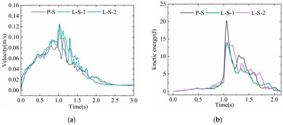
Figure 11.
Particle velocities and soil kinetic energy. (a) Particle velocities; (b) Soil kinetic energy.
3.1.2. Soil Disturbance Conditions
As shown in Figure 12, the two types of bionic digging shovels performed well in soil disturbance during the simulation. At 0.54 s, the digging shovel completely entered the discrete element soil bin, and the tip began to shear the soil. The soil was compressed and moved upwards along the shovel surface, creating soil bulging. At 0.9 s, the soil was lifted to a height similar to the starting point of the simulation, and internal particles gained significant kinetic energy. The high-speed red particle area moved to the upper surface. At 1.14 s, under the influence of gravity, the soil disturbance area formed by the bionic backfilling shovel took on a typical pit shape. Compared to the traditional flat shovel structure, the bionic corrugated shovel design increases the movement speed of surrounding soil and enables more effective soil fragmentation, thereby confirming that the bionic digging shovel exhibits lower digging resistance. Both L-S-1 and L-S-2 demonstrate superior soil disturbance effects compared to the flat shovel P-S.
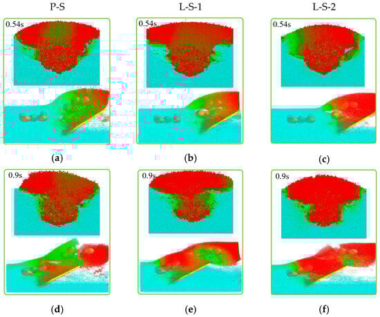
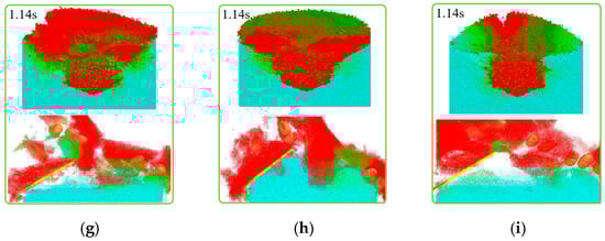
Figure 12.
Soil particle disturbance in cross-section and longitudinal section for different digging shovels. (a,c,f) under P-S at 0.54 s, 0.9 s, and 1.14 s, respectively; (b,d,g) under L-S-1 at 0.54 s, 0.9 s, and 1.14 s, respectively; (e,h,i) under L-S-2 at 0.54 s, 0.9 s, and 1.14 s, respectively.
All three types of digging shovels caused significant disturbance to the soil structure during operation. A strong internal shear force was formed between the excavated soil and the unexcavated soil, leading to torsional deformation of the soil layers and a gradual increase in soil porosity. Under the disturbance, the internal soil particles gained substantial kinetic energy, and as the digging shovel was lifted, the red high-speed region gradually shifted toward the upper surface. Compared to the flat digging shovel, the biomimetic digging shovel exhibited a larger red high-speed region, indicating that it caused a higher degree of soil disturbance during operation. This results in more effective soil fragmentation and loosening, allowing potatoes to be separated more cleanly. In certain compacted or heavy soils, it can effectively reduce the forward resistance of the digging shovel.
The calculation results of soil volumetric density, maximum soil disturbance rate, and density change rate after simulated excavation are shown in Figure 13. Analysis indicates that there is no significant difference between the biomimetic digging shovel and the regular flat shovel in terms of soil volumetric change rate (B) and density change rate (K), although the values of the biomimetic digging shovel are still slightly higher than those of the regular flat shovel. The main advantage of the biomimetic digging shovel in soil disturbance is reflected in the soil disturbance rate (D). The soil disturbance rates corresponding to the biomimetic digging shovel are 36.42% (L-S-1), and 37.43% (L-S-2), while the disturbance rate for the regular flat shovel is 29.32%.
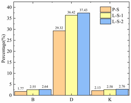
Figure 13.
Comparison of soil disturbance indices.
To accurately compare the soil disturbance caused by different bionic digging shovels during operation, the total kinetic energy of particles within the volume is solved in EDEM 2022. As shown in Figure 11b, before 0.06 s, the digging shovel has not yet contacted the soil, so the kinetic energy is zero. From 0.06 s to 0.46 s, kinetic energy increases gradually due to the shovel’s disruption of the soil. From 0.46 s to 0.54 s, kinetic energy slightly decreases due to soil being lifted, then continues to increase until it reaches the maximum value. After this, some soil particles begin sliding from the underground soil layer surface to the ground, and the kinetic energy gradually decreases. At 1.14 s, the soil lifted by the digging shovel begins to fall, and the soil’s kinetic energy increases again, reaching a local maximum at 1.14 s. Finally, all soil particles fall, and the kinetic energy decreases to a stable state close to zero. The maximum total particle kinetic energy is for P-S (20.2556 J), and the minimum is for L-S-2 (13.2231 J), followed by L-S-1 (13.9744 J). The total particle kinetic energy reflects the energy imparted by the shovel to mobilize the soil mass. A lower peak and average total kinetic energy for the bionic shovels (L-S-1, L-S-2) compared to the flat shovel (P-S) suggests that, for the same forward speed and digging depth, the bionic designs transfer less energy into accelerating and disturbing the soil bulk. This observation is consistent with the lower measured resistance (Figure 14a), indicating that a smaller portion of the tractor’s work is converted into soil kinetic energy, potentially leading to reduced overall energy consumption during the digging operation. However, a complete energy balance would require accounting for all energy dissipation pathways (e.g., soil deformation, frictional heating). Although particle kinetic energy does not directly indicate reduced energy consumption of the digging shovel, it serves as a consistent and quantifiable metric for comparative evaluation of different shovel designs in simulation studies.
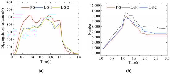
Figure 14.
Digging resistance and number of soil bond fractures. (a) Digging resistance over time for different levels; (b) Cumulative number of soil bond breaks over time for different levels.
3.1.3. Analysis of Resistance Reduction, Soil Fragmentation, and Force Characteristics
The size of the digging resistance is mainly affected by factors such as soil adhesion and entry angle. The digging resistance data and the number of soil bonding bond breaks during the simulation process are exported using the Analyst post-processing module of EDEM. The average digging resistance during the operation of the digging shovel is calculated and plotted using OriginPro 2024b software, as shown in Figure 13.
As shown in Figure 14a, when the tip of the digging shovel contacts the soil, the digging resistance immediately fluctuates and shows a continuous upward trend. At approximately 0.2 s, the first peak value N is reached, after which the shovel completely enters the soil and continues operation, with the resistance gradually stabilizing. From 0.54 s to 0.9 s, the digging resistance shows a secondary increase due to the soil compaction phenomenon. Subsequently, as the soil is excavated, the digging resistance gradually decreases. Compared to the flat digging shovel, the bionic shovel surface with its corrugated structure effectively channels soil flow, reduces the number of soil particles carried by the shovel surface, and mitigates soil compaction, significantly lowering digging resistance.
Due to the excessive computational load of direct simulation, soil fragmentation was quantified using a counting approach based on the number of soil particle bond breakage events. This metric was employed to characterize the soil fragmentation performance of different digging shovels. As shown in Figure 14b, the bionic digging shovel exhibits superior soil fragmentation performance compared with the flat shovel. Among the corrugated shovel configurations, L-S-2 demonstrates a markedly higher level of soil fragmentation than L-S-1.
As shown in Table 4, the 95% confidence intervals (CIs) for digging resistance reduction and soil fragmentation improvement were calculated based on three repeated trials. Compared with the conventional flat shovel (P-S), the L-S-2 shovel achieved an average digging resistance reduction of 13.87% (95% CI: 12.15–15.61%), while the L-S-1 shovel achieved a reduction of 12.03% (95% CI: 10.28–13.80%). In both cases, the confidence intervals do not include zero, indicating a consistently lower digging resistance for the bionic shovels relative to the flat shovel, with L-S-2 showing a slightly greater reduction. In terms of soil fragmentation performance, the L-S-1 and L-S-2 shovels increased the fragmentation rate by 21.34% (95% CI: 19.12–23.56%) and 20.67% (95% CI: 18.45–22.89%), respectively, compared with the flat shovel (P-S). These confidence intervals also exclude zero, suggesting that both bionic shovels provide enhanced soil fragmentation performance relative to the conventional flat shovel.
Table 4.
Average digging resistance and number of bonding bond fractures for each digging shovel.
Figure 15 illustrates the force distribution on the surfaces of the conventional flat shovel (P-S) and the bionic digging shovels (L-S-1 and L-S-2) during the simulation. The force contours at the stable working stage (0.9 s) were selected for analysis. The results show that the conventional flat shovel (P-S) experiences a substantially higher overall force. In contrast, the forces acting on the bionic shovels are mainly concentrated on the lateral edges of the shovel tip and the central tip region where the corrugated structure is not applied. Compared with the flat shovel, the bionic shovels exhibit a clear reduction in the overall force acting on their surfaces.
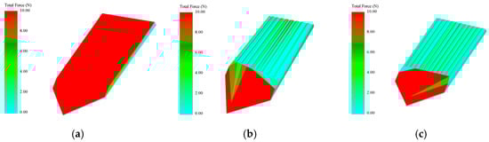
Figure 15.
Force distribution nephograms of the three digging shovels. (a) Conventional flat shovel P-S; (b) Bionic digging shovel L-S-1; (c) Bionic digging shovel L-S-2.
To further verify the influence of the scaling of the corrugated structure on the strength and wear resistance of the digging shovel, static finite element analysis was performed on two bionic digging shovels. According to relevant literature [35], the operating resistance of a single potato digging shovel is approximately 2000 N for horizontal resistance and about 500 N for vertical resistance. These forces were applied to the shovel surface, and the fixed end of the shovel handle was constrained. The mesh division adopted 0.5 mm. The final finite element model of L-S-1 has a total of 1,320,867 nodes and 774,302 solid elements; L-S-2 has a total of 1,408,321 nodes and 790,212 solid elements. ANSYS Workbench 2024 R1 was used for solving. The material property was set to 65Mn steel (density: 7830, shear modulus: 81,900 MPa, yield strength: 430 MPa, Poisson’s ratio: 0.3, ultimate tensile strength: 735 MPa).
The results of the finite element analysis show that, as depicted in Figure 16a, the maximum deformation of the bionic excavating shovel L-S-1 is 1.4134 × 10⁻⁴ mm, and the maximum equivalent stress is 6.01 MPa; as shown in Figure 16b, the maximum deformation of the bionic excavating shovel L-S-2 is 1.2218 × 10⁻⁴ mm, and the maximum equivalent stress is 5.74 MPa, which is mainly concentrated in the transition area between the shovel tip and the corrugated structure, but it is still much lower than the yield strength of 65Mn steel. In addition, after the shovel tip is subjected to laser cladding treatment (the thickness of the FJG-S52 iron-based alloy layer is approximately 1.5 mm), the surface hardness is expected to increase to HRC 55-60, significantly enhancing wear resistance. Although the introduction of the corrugated structure increases the surface area, stress concentration is effectively avoided by optimizing the corrugated amplitude. Therefore, based on EDEM load verification and static finite element analysis, it is shown that the scaled design of the corrugated structure can ensure the mechanical strength and service life of the excavating shovel.
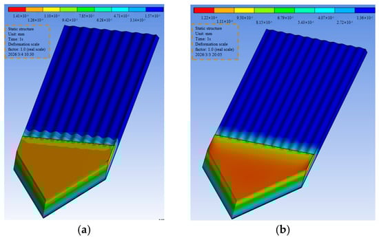
Figure 16.
Results of static finite element analysis of two bionic digging shovels. (a) Bionic digging shovel L-S-1; (b) Bionic digging shovel L-S-2.
3.1.4. The Effect of Speed on Digging Performance
Based on the above analyses, the corrugated structure, as a biomimetic design element, effectively enhances the resistance reduction performance of the digging shovel. Among the tested configurations, the L-S-2 digging shovel exhibited the best overall performance and was therefore selected to investigate the influence of operating speed on digging behavior. In the discrete element simulations, the digging shovel was operated at three forward speeds: 0.4 m/s, 0.5 m/s, and 0.6 m/s. The excavation process curves corresponding to these speeds are presented in Figure 17.
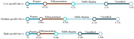
Figure 17.
The timeline of the digging operation at different speeds.
Figure 18 presents the variations in horizontal digging resistance, vertical digging resistance, total kinetic energy of soil particles, and soil particle bond breakage at different forward speeds. Overall, the trends of all parameters are consistent with the previous analyses, with the primary differences reflected in the magnitude of variation. As the forward speed increases, the horizontal digging resistance of the shovel rises more rapidly, whereas the growth rates of vertical digging resistance and soil particle kinetic energy gradually decrease. These results indicate that increasing the forward speed enhances soil fragmentation by promoting more intensive disruption of soil bonding during the digging process.
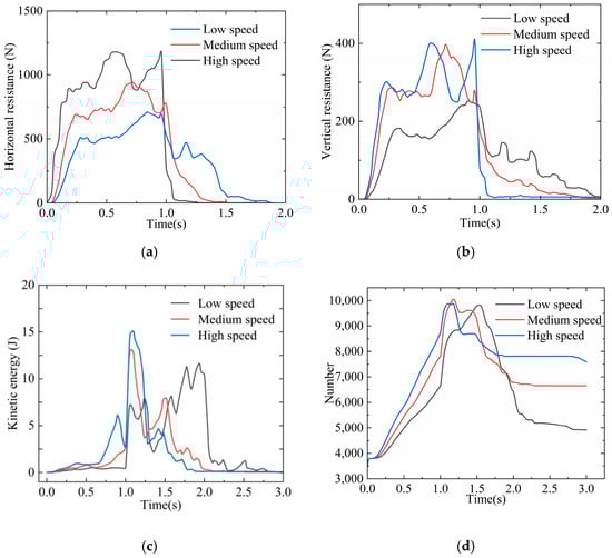
Figure 18.
Digging performance curves at different forward speeds: (a) Horizontal force variation curve; (b) Vertical force variation curve; (c) Soil kinetic energy variation curve; (d) Soil particle bond breakage curve.
Figure 19 illustrates the soil disturbance conditions at several typical moments under different forward speeds. During the initial soil entry phase of the digging shovel, the disturbance differences caused by varying speeds are not significant. As the operation continues, higher speeds increasingly disturb the soil particles, resulting in greater displacement and kinetic energy. When the digging shovel leaves the soil, the higher the speed, the higher the soil particles are thrown, and the greater the energy of the impact when they fall back to the ground, causing more soil to be uplifted and churned to the surface. The quantitative performance indicators in Table 5 further demonstrate that all indicators increase with speed. Although increasing the speed enhances the soil disturbance effect, it also causes a significant increase in digging resistance, thereby raising the energy consumption of the digging shovel. Therefore, the choice of forward speed should be weighed according to actual agronomic conditions.
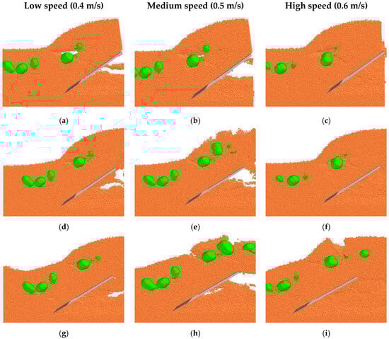
Figure 19.
Soil disturbance at different forward speeds: (a,d,g) representative instances under low-speed digging; (b,e,h) representative instances under medium-speed digging; and (c,f,i) representative instances under high-speed digging.
Table 5.
Quantitative analysis of L-S-2 digging performance at different forward speeds.
The results indicate that incorporating a corrugated structure as a biomimetic design element can effectively reduce the digging resistance of the shovel. Based on a comprehensive analysis of the simulation results, the bionic digging shovel L-S-2, which exhibited the best overall performance in terms of resistance reduction and soil fragmentation, was selected for subsequent material modification tests to further improve its resistance reduction performance.
3.2. Soil Bin Test
3.2.1. Comparison of Digging Resistance
The horizontal digging resistance of the shovels was measured using the data acquisition system of the soil bin test bench, and each test condition was repeated three times. During the experiments, the data acquisition system recorded resistance–time curves for different shovel configurations under various test conditions. The test parameters included soil moisture contents of 15%, 18%, and 20%, and forward speeds of 0.4 m/s, 0.5 m/s, and 0.6 m/s. The corresponding resistance–time curves are presented in Figure 20.
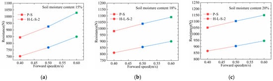
Figure 20.
Soil bin resistance tests of P-S and H-L-S-2 under different test conditions. (a) soil moisture content of 15%; (b) soil moisture content of 18% and (c) soil moisture content of 20%.
To compare the resistance reduction effects between the flat digging shovel (P-S) and the composite bionic digging shovel (H-L-S-2), the resistance reduction rate was calculated using the following formula: Digging Resistance reduction rate (%) = [(Digging resistance of P-S—Digging resistance of H-L-S-2)/Digging resistance of P-S] × 100%. Under different forward speeds and soil moisture content conditions, the resistance reduction rates of the two digging shovels are shown in Table 5.
As shown in Table 6, when the soil moisture content was kept constant, the digging resistance of the composite bionic digging shovel (H-L-S-2) increased with the increase in forward speed; compared with the flat digging shovel (P-S), this composite bionic digging shovel showed a significant resistance reduction effect, with digging resistance reduction rate of 16.72~17.43%. When the forward speed was kept constant, the digging resistance of both the composite bionic digging shovel (H-L-S-2) and the flat digging shovel (P-S) increased with the increase in soil moisture content; compared with the flat digging shovel, the digging resistance reduction rate of the composite bionic digging shovel was 16.97~18.02%. The average digging resistance of the composite bionic digging shovel (H-L-S-2) was 843.97 N, and that of the traditional flat digging shovel (P-S) was 1011.25 N. The average digging resistance reduction rate of the composite bionic digging shovel (H-L-S-2) reached 17.46%, which further verified that the resistance reduction effect of the composite bionic digging shovel was superior to that of the traditional flat digging shovel (P-S).
Table 6.
Results of the soil tray comparison test.
3.2.2. Comparative Analysis of Soil Disturbance
Figure 21 illustrates the soil disturbance caused by the potato digging shovels P-S and H-L-S-2 at different operating speeds. Compared with the simulated disturbance conditions described earlier, the flow pattern of soil particles in the simulation closely resembles that of the actual digging process. The discrete element parameters used in the simulation are close to those of real soil, indicating that the simulation can accurately replicate the scenario of digging shovels interacting with soil.
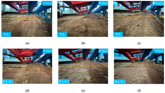
Figure 21.
Comparison of soil disturbance between two types of digging shovels: (a–c) Soil disturbance by the P-S digging shovel at different forward speeds; and (d–f) Soil disturbance by the h-l-s-2 digging shovel at different forward speeds.
As shown in Figure 21a–c, the planar shovel P-S exhibits significant differences in soil disturbance at various forward speeds. As the speed increases, the amount of displaced topsoil increases noticeably, which tends to cause soil accumulation during actual digging operations and may lead to machine clogging. In contrast, Figure 21d–f demonstrate that the bionic composite shovel H-L-S-2 produces relatively consistent soil disturbance across different speeds. Moreover, thanks to its corrugated flow-enhancing design and hydrophobic material properties, the topsoil flows more rapidly and accumulates less. This effectively reduces the risk of clogging and decreases digging resistance.
3.2.3. Comparison of Soil Adhesion Reduction
The two distinct digging shovels exhibit different degrees of soil adhesion. As shown in Figure 22, compared to the conventional planar shovel P-S (Figure 22a,b), the bionic composite shovel H-L-S-2 (Figure 22c,d) demonstrates significantly less soil accumulation. This is attributed to the corrugated surface of H-L-S-2, which enhances soil flow velocity and reduces retention on the shovel surface. Additionally, the hydrophobic PTFE material minimizes soil adherence to the corrugated structure. Adhesive soil, composed mainly of moist soil and clay, tends to accumulate along the sides and bolt connections of the shovels. Consequently, the bionic composite shovel H-L-S-2 shows relatively less accumulation of adhesive mass. In contrast, the conventional planar shovel P-S suffers from severe adhesion, primarily concentrated across its surface.
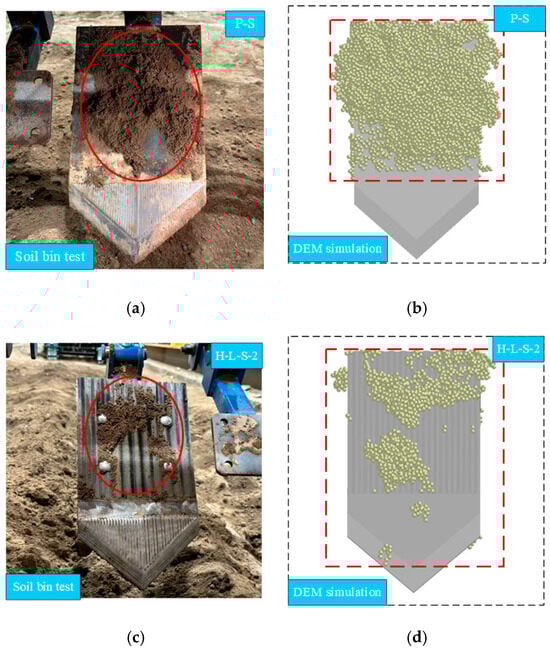
Figure 22.
Soil Adhesion Status on Digging Shovels: (a) Conventional Planar Shovel (P-S) Prototype; (b) Simulated Adhesion Status of P-S; (c) Bionic Composite Shovel (H-L-S-2) Prototype Developed in This Study, (d) Simulated Adhesion Status of H-L-S-2.
Furthermore, comparison between soil bin tests (Figure 22a,c) and simulation tests (Figure 22b,d) reveals consistent adhesion behavior, confirming that the simulation accurately replicates real-world soil adhesion scenarios. The adhesive mass for H-L-S-2 was measured at 0.05 kg, substantially lower than the 0.08 kg for P-S, representing a reduction rate of 37.5%. Simulation results further support this, showing 1368 adhered particles for H-L-S-2 compared to2,327 for P-S, corresponding to a reduction of 41.2%. These findings demonstrate that H-L-S-2 offers a significant advantage over P-S in reducing soil adhesion.
The forward speeds (0.4–0.6 m/s) and soil moisture range (15–20%) tested in this study were selected based on typical agronomic practices and harvesting conditions in the target potato cultivation regions of Northwest China, aiming to balance operational efficiency and energy consumption. While these parameters cover common field scenarios, the performance of the bionic composite shovel under extreme operating conditions—such as speeds below 0.3 m/s or above 0.8 m/s, or under very high (>25%) or very low (<10%) soil moisture—remains to be investigated. Future work should consider these boundary conditions to fully evaluate the robustness and performance limits of the design, providing a more comprehensive basis for its adaptation to diverse geographical regions and soil types.
4. Conclusions and Perspectives
This study takes the corrugated structure of the white grub’s body surface as a bionic prototype and proposes a composite potato digging shovel design method that combines bionic structure and material modification. The main conclusions are as follows:
- The corrugated curves of the white grub’s back were obtained through reverse engineering, and two longitudinal corrugated bionic digging shovel models were constructed. Discrete element simulation showed that the longitudinal corrugated shovel L-S-2 exhibited optimal resistance reduction and soil fragmentation performance, reducing operational resistance by 13.87% and increasing soil fragmentation rate by 20.67% compared to the flat shovel.
- By embedding PTFE hydrophobic material into the shovel surface of L-S-2 and applying laser cladding treatment to the shovel tip, a composite bionic shovel H-L-S-2 was fabricated. Soil-bin tests indicated that this shovel demonstrated stable resistance reduction and anti-adhesion performance under different forward speeds and soil moisture contents, with an average resistance reduction rate of 17.46% and a reduction range of 16.72% to 18.02%. Both discrete element simulation and soil-bin test results consistently confirmed the shovel’s excellent anti-adhesion performance: the adhered particle count decreased by 41.2% in simulation, and the soil adhesion mass was reduced by 37.5% in soil-bin tests.
- The coupled design of the bionic corrugated structure and surface functional materials has significantly improved the interaction behavior at the interface and anti-adhesion performance under highly cohesive soil conditions. This provides a feasible bionic integrated solution for reducing adhesion and resistance of potato digging shovels.
This study has confirmed the important role of the combination of structural bionics and material modification in improving the performance of agricultural soil-contacting components, and provides a theoretical basis and technical reference for the subsequent bionic design and engineering application of agricultural machinery.
Author Contributions
Conceptualization, C.L. and H.W.; Data curation, C.L. Formal analysis, C.L.; Funding acquisition, W.Z. and R.S.; Investigation, C.L. and H.W.; Project administration, L.L. and R.S.; Resources, H.W. and W.Z.; Software, C.L.; Supervision, H.W. and W.Z.; Validation, C.L.; Writing—original draft, C.L. and H.W.; Writing—review and editing, W.Z. All authors have read and agreed to the published version of the manuscript.
Funding
This research was supported by the National Key Research and Development Program (2023YFD170190302), the Achievement Transformation Project of Gansu Agricultural University (GSAU-JSYF-2024-51), the Gansu Province Integration of Research and Production Science and Technology Tackling and Empowerment Plan Project (25FNNF001-2), and the Publicly Recruited Doctoral Research Initiation Project of Gansu Agricultural University: Key Technologies for resistance reduction Soil Crushing and Efficient Separation in Potato Harvesting in the Northwest Dry Farming Region.
Institutional Review Board Statement
Informed consent was obtained from the animal owners for the use of animals in this study. All procedures involving animals were conducted in compliance with the Regulations for the Administration of Affairs Concerning Experimental Animals (Ministry of Science and Technology, China; revised in June 2004). The sample collection protocols were approved by the Animal Ethics Committee of Gansu Agricultural University (Approval No. GSAU-Eth-VMC-2025-052).
Data Availability Statement
The original contributions presented in this study are included in the article. Further inquiries can be directed to the corresponding author.
Conflicts of Interest
The authors declare no conflicts of interest.
References
- Rodríguez, L.E. Origins and Evolution of Cultivated Potato. A review. Agron. Colomb. 2010, 28, 9–17. [Google Scholar]
- Hu, X.; Jiang, H.; Liu, Z.; Gao, M.; Liu, G.; Tian, S.; Zeng, F. The Global Potato-Processing Industry: A Review of Production, Products, Quality and Sustainability. Foods 2025, 14, 1758. [Google Scholar] [CrossRef]
- Awuah, E.; Zhou, J.; Liang, Z.; Aikins, K.A.; Gbenontin, B.V.; Mecha, P.; Makange, N.R. Parametric Analysis and Numerical Optimisation of Jerusalem Artichoke Vibrating Digging Shovel Using Discrete Element Method. Soil Tillage Res. 2022, 219, 105344. [Google Scholar] [CrossRef]
- Yue, Y.; Zhang, Q.; Dong, B.; Li, J. Application of Discrete Element Method to Potato Harvesting Machinery: A Review. Agriculture 2025, 15, 315. [Google Scholar] [CrossRef]
- Yang, R.; Xu, W.; Pan, Z.; Zhang, H.; Deng, Z. Design and Experiment Of a Bionic Drag-Reducing Digger for Tuberous Crops Under Heavy Soil Conditions. PLoS ONE 2025, 20, e318526. [Google Scholar] [CrossRef]
- Jia, H.; Wang, W.; Wang, W.; Zheng, J.; Wang, Q.; Zhuang, J. Application of Anti-Adhesion Structure Based on Earthworm Motion Characteristics. Soil Tillage Res. 2018, 178, 159–166. [Google Scholar] [CrossRef]
- Wang, Y.; Li, N.; Ma, Y.; Tong, J.; Pfleging, W.; Sun, J. Field Experiments Evaluating a Biomimetic Shark-Inspired (Bios) Subsoiler For Tillage Resistance Reduction. Soil Tillage Res. 2020, 196, 104432. [Google Scholar] [CrossRef]
- Zhang, F.; Luo, Z.; Zheng, E.; Han, L.; Qian, J.; Yao, H.; Shi, Y.; Wang, X. Imitating pangolin scale structure for reducing adhesion and resistance of rotary tillage in wet-adhesive soil. Soil Tillage Res. 2025, 245, 106306. [Google Scholar] [CrossRef]
- Francetto, T.R.; Alonço, A.D.S.; Brandelero, C.; Machado, O.D.D.C.; Veit, A.A.; Carpes, D.P. Disturbance of Ultisol soil based on interactions between furrow openers and coulters for the no-tillage system. Span. J. Agric. Res. 2016, 14, 208. [Google Scholar] [CrossRef]
- Li, J.; Gu, T.; Li, X.; Wang, Z.; Hu, B.; Ma, Y. Analysis and Experiment of The Bionic Drag Reduction Characteristics of Potato Digging Shovels on Clayey Black Soil Conditions. Trans. Chin. Soc. Agric. Eng. (Trans. CSAE) 2023, 39, 108315. (In Chinese) [Google Scholar]
- Zhang, Z.; Xue, H.; Wang, Y.; Xie, K.; Deng, Y. Design and Experiment of Panax notoginseng Bionic Excavating Shovel Based on EDEM. Trans. Chin. Soc. Agric. Mach. 2022, 53, 100–111. (In Chinese) [Google Scholar]
- Li, J.; Jiang, X.; Ma, Y.; Tong, J.; Hu, B. Bionic Design of a Potato Digging Shovel with Drag Reduction Based on the Discrete Element Method (DEM) in Clay Soil. Appl. Sci. 2020, 10, 7096. [Google Scholar] [CrossRef]
- Ji, W.; Chen, D.; Jia, H.; Tong, J. Experimental Investigation into Soil-Cutting Performance of the Claws of Mole Rat (Scaptochirus moschatus). J. Bionic Eng. 2010, 7, S166–S171. [Google Scholar] [CrossRef]
- Tong, J.; Ji, W.; Jia, H.; Chen, D.; Yang, X. Design and Tests of Biomimetic Blades for Soil-rototilling and Stubble-breaking. J. Bionic Eng. 2015, 12, 495–503. [Google Scholar] [CrossRef]
- Yang, Y.; Li, M.; Tong, J.; Ma, Y. Study on the Interaction Between Soil and the Five-Claw Combination of a Mole Using the Discrete Element Method. Appl. Bionics Biomech. 2018, 2018, 7854052. [Google Scholar] [CrossRef]
- Zhang, L.; Zhai, Y.; Chen, J.; Zhang, Z.; Huang, S. Optimization Design and Performance Study of a Subsoiler Underlying The Tea Garden Subsoiling Mechanism Based on Bionics and EDEM. Soil Tillage Res. 2022, 220, 105375. [Google Scholar] [CrossRef]
- Wang, Y.; Xue, W.; Ma, Y.; Tong, J.; Liu, X.; Sun, J. DEM and Soil Bin Study on a Biomimetic Disc Furrow Opener. Comput. Electron. Agric. 2019, 156, 209–216. [Google Scholar] [CrossRef]
- Soni, P.; Salokhe, V.M. Influence of Dimensions of UHMW-PE Protuberances on Sliding Resistance and Normal Adhesion of Bangkok Clay Soil to Biomimetic Plates. J. Bionic Eng. 2006, 3, 63–71. [Google Scholar] [CrossRef]
- Wang, H.; Zhao, W.; Sun, W.; Meng, Y.; Gao, K.; Shi, R. Design and Experiment of Potato Combine Harvester Based on Multiple Steering Modes and Anti Adhesion Soil Fragmentation Type. Trans. Chin. Soc. Agric. Mach. 2025, 56, 252–263. (In Chinese) [Google Scholar]
- Momozu, M.; Oida, A.; Yamazaki, M.; Koolen, A.J. Simulation of a soil loosening process by means of the modified distinct element method. J. Terramech. 2002, 39, 207–220. [Google Scholar] [CrossRef]
- Tsuji, T.; Nakagawa, Y.; Matsumoto, N.; Kadono, Y.; Takayama, T.; Tanaka, T. 3-D DEM simulation of cohesive soil-pushing behavior by bulldozer blade. J. Terramech. 2012, 49, 37–47. [Google Scholar] [CrossRef]
- Ucgul, M.; Fielke, J.M.; Saunders, C. Three-Dimensional Discrete Element Modelling (DEM) of Tillage: Accounting for Soil Cohesion and Adhesion. Biosyst. Eng. 2015, 129, 298–306. [Google Scholar] [CrossRef]
- Zeng, Z.; Ma, X.; Chen, Y.; Qi, L. Modelling Residue Incorporation of Selected Chisel Ploughing Tools Using the Discrete Element Method (DEM). Soil Tillage Res. 2020, 197, 104505. [Google Scholar] [CrossRef]
- Aikins, K.A.; Barr, J.B.; Antille, D.L.; Ucgul, M.; Jensen, T.A.; Desbiolles, J.M.A. Analysis of Effect of Bentleg Opener Geometry on Performance in Cohesive Soil Using The Discrete Element Method. Biosyst. Eng. 2021, 209, 106–124. [Google Scholar] [CrossRef]
- Dai, Q.; Qiu, S.; Huang, W.; Wang, X. Non-sticky and Free-forward Performances of Grubs against Soil. Colloids Surf. B 2020, 191, 111006. [Google Scholar] [CrossRef]
- Wang, H.; Zhao, W.; Sun, W.; Liu, X.; Shi, R.; Zhang, H.; Chen, P.; Gao, K. The Design and Experimentation of a Wheeled-Chassis Potato Combine Harvester with Integrated Bagging and Ton Bag-Lifting Systems. Agriculture 2024, 14, 1461. [Google Scholar] [CrossRef]
- Shi, L.R.; Sun, W.; Zhao, W.Y.; Yang, X.P.; Feng, B. Parameter Determination and Validation of Discrete Element Model of Seed Potato Mechanical Seeding. Trans. Chin. Soc. Agric. Eng. (Trans. CSAE) 2018, 35, 35–42. (In Chinese) [Google Scholar]
- Ucgul, M.; Fielke, J.M.; Saunders, C. 3D Dem Tillage Simulation: Validation of a Hysteretic Spring (Plastic) Contact Model For a Sweep Tool Operating in a Cohesionless Soil. Soil Tillage Res. 2014, 144, 220–227. [Google Scholar] [CrossRef]
- Chen, M.D.; Liu, X.T.; Hu, P.X.; Zhai, X.T.; Han, Z.L.; Shi, Y.L.; Zhu, W.J.; Wang, D.W.; He, X.N.; Shang, S.Q. Study on Rotor Vibration Potato-Soil Separation Device for Potato Harvester Using Dem-Mbd Coupling Simulation. Comput. Electron. Agric. 2024, 218, 108638. [Google Scholar] [CrossRef]
- Ding, Q.S.; Ren, J.; Belal, E.A.; Zhao, J.; Ge, S.; Li, Y. DEM Analysis of Subsoiling Process in Wet Clayey Paddy Soil. J. Trans. Chin. Soc. Agric. Mach. 2017, 48, 38–48. [Google Scholar]
- Hang, C.; Gao, X.; Yuan, M.; Huang, Y.; Zhu, R. Discrete Element Simulations and Experiments of Soil Disturbance As Affected by The Tine Spacing of Subsoiler. J. Biosyst. Eng. 2017, 168, 73–82. [Google Scholar] [CrossRef]
- Zhang, P.; Li, F.; Wang, F. Optimization and test of ginger-shaking and harvesting device based on EDEM software. Comput. Electron. Agric. 2023, 213, 108257. [Google Scholar] [CrossRef]
- Jia, B.; Sun, W.; Zhao, Z.; Wang, H.; Zhang, H.; Liu, X.; Li, H. Design and Field Test of a Remotely Controlled Self-propelled Potato Harvester with Manual Sorting Platform. Am. J. Potato Res. 2023, 100, 193–209. [Google Scholar] [CrossRef]
- Wang, X.; Fang, W.; Han, D.; Chen, X. Review of the Research on Soil Disturbance by Tools. Appl. Sci. 2023, 13, 338. [Google Scholar] [CrossRef]
- Yu, J.; Ma, Y.; Wang, S.; Xu, Z.; Liu, X.; Wang, H.; Qi, H.; Han, L.; Zhuang, J. 3D Finite Element Simulation and Experimental Validation of a Mole Rat’s Digit Inspired Biomimetic Potato Digging Shovel. Appl. Sci. 2022, 12, 1761. [Google Scholar] [CrossRef]


Disclaimer/Publisher’s Note: The statements, opinions and data contained in all publications are solely those of the individual author(s) and contributor(s) and not of MDPI and/or the editor(s). MDPI and/or the editor(s) disclaim responsibility for any injury to people or property resulting from any ideas, methods, instructions or products referred to in the content. |
© 2026 by the authors. Licensee MDPI, Basel, Switzerland. This article is an open access article distributed under the terms and conditions of the Creative Commons Attribution (CC BY) license.