Abstract
To improve traction efficiency and reduce fuel consumption during tractor tillage operations, a coordinated control method for electro-hydraulic hitch depth and tractor speed was proposed. Based on theoretical analysis, a dynamic model of the tractor–implement system during tillage was established. The principles of coordinated control were developed, and a comprehensive performance evaluation index considering both efficiency and economic performance of the tractor was proposed to optimize the coordinated control objectives. A depth controller and a speed controller were, respectively, designed based on the sliding mode control algorithm. A hardware-in-the-loop test platform for coordinated control of electro-hydraulic hitch depth and travel speed was established via CAN communication. Comparative experiments were conducted under three operational conditions (Condition 1: tillage depth 16 cm, soil specific resistance 2.5–3.5 N/cm2; Condition 2: 20 cm, 3.5–4.5 N/cm2; Condition 3: 24 cm, 4.5–5.5 N/cm2) against the conventional single depth control method under full throttle. Results demonstrated that the coordinated depth-speed control method improved the overall tractor efficiency-economy by 50.0%, 33.3%, and 26.7% under these respective conditions compared to the single depth control method. This method not only ensures operation quality but also enhances the comprehensive performance of the tractor, effectively improving traction efficiency and reducing fuel consumption. Moreover, it demonstrates better adaptability to varying field conditions.
1. Introduction
The tractor stands as one of the most widely utilized agricultural machines, serving as a power source that couples with various implements to perform multiple operations—including plowing, seeding, fertilization, irrigation, and harvesting [1,2]. Due to the complexity of field conditions and the diversity of agricultural operations, tractors are often subject to complex disturbances and large fluctuations in draft resistance during work [3,4]. Conventional tractors mostly operate with fixed parameters, which limits their ability to adapt in real time to variations in soil properties and operational loads. As a result, the drive wheels are prone to excessive slip, which not only disrupts the soil environment but also reduces operational efficiency and leads to increased fuel consumption [5,6].
Improving tractor efficiency and reducing fuel consumption during field operations have long been prominent and compelling research topic in agricultural engineering [7]. Numerous scholars have made significant contributions to this field. Zhang et al. proposed a slip ratio control method aimed at enhancing traction efficiency during tractor tillage operations. When the slip ratio exceeded a certain threshold, the system reduce the tillage depth to decrease the tractor’s load, thereby lowering the slip ratio. Experimental results showed that this method effectively maintained the slip ratio within the desired range and significantly improved traction efficiency during operation [8]. Zhao et al. developed an integrated position–slip ratio control method, which was experimentally validated to maintain tillage depth while simultaneously controlling the slip ratio, thus improving overall tillage efficiency [9]. Han et al. introduced a variable target slip ratio–position control strategy, in which the target slip ratio was dynamically adjusted to the optimal value identified by the system, rather than being fixed. Results showed that this method could maintain the slip ratio near its optimum under varying soil conditions [10]. Cui et al. proposed an adaptive control method with variable weighting factors for an electro-hydraulic hitch system. Adaptive control rules were developed for three feedback parameters—tillage depth, draft force, and slip ratio. Experimental results indicated that this method not only improved the tractor’s fuel economy but also reduced impact forces on the hitch system [11].
The aforementioned methods can effectively enhance tractor traction efficiency and reduce fuel consumption to some extent. However, these approaches primarily rely on adjusting tillage depth to control wheel slip, which often results in insufficient depth control accuracy and unstable operational quality during the process. This limitation becomes particularly prominent under complex and variable field conditions, where single-factor control strategies struggle to cope with dynamic disturbances such as fluctuating soil resistance and varying operational loads. Consequently, a growing number of studies have begun to focus on multi-parameter coordinated control systems, aiming to develop more intelligent control strategies for comprehensive improvement of overall tractor operational performance.
Zhang et al. proposed an integrated traction and ballast control method based on load transfer. By adjusting the position of the battery pack on an electric tractor along with tillage depth, the tractor’s center of gravity is shifted, thereby modifying the vertical loads on the front and rear wheels. Test results demonstrated that the integrated control method outperformed traction-only control in terms of both tillage depth uniformity and traction performance [12]. Wang et al. developed a switching control method for tillage speed and slip ratio. When soil conditions change, the system switches between dual target—tillage speed and slip ratio—without adjusting the tillage depth. Simulation and experimental results showed that this method effectively controls slip during tillage operations while maintaining the desired working speed, thereby improving operational efficiency [13]. Kumari et al. aimed to minimize fuel consumption during rotary tillage by developing an embedded control system that adjusts gear selection and throttle position to achieve optimal fuel efficiency at different tillage depths. Experiments conducted at 80 mm and 120 mm depths verified the effectiveness of the proposed embedded system [14].
Tillage depth and forward speed are two critical parameters influencing tractor field performance. Tillage depth directly affects soil pulverization quality and agronomic outcomes, while forward speed determines traction load, slip ratio, and fuel consumption. A strong coupling relationship exists between these parameters; improper coordination may lead to reduced traction efficiency, significant fluctuations in draft resistance, and ultimately a decline in the both economic and operational performance of the tractor. In response, this study proposes a coordinated control method for tractor tillage depth and forward speed. By analyzing the longitudinal force balance of the electro-hydraulic hitch–implement system, a dynamic model of the tractor–implement operation unit was established. A coordinated depth–speed control strategy was designed, and a comprehensive performance index integrating both economic and efficiency metrics was formulated to optimize the coordination control objectives. Based on this framework, dedicated controllers for tillage depth and forward speed were developed. A hardware-in-the-loop experimental platform for depth–speed coordinated control was established using CAN communication, and experimental validation of the proposed method was conducted.
2. Materials and Methods
2.1. Theoretical Modeling
The tractor is connected to the moldboard plow through a three-point hitch system and provides the driving power required for the plow to overcome the tillage resistance caused by soil shearing and crushing, thereby enabling forward motion [15,16]. Since moldboard plowing operations are typically performed in straight lines, the following assumptions are made to simplify the modeling of the tractor–implement system:
- (a)
- Only the linear motion of the tractor in the forward direction is considered;
- (b)
- The stiffness of the components of the three-point hitch is neglected, and the tractor and plow are regarded as a single rigid body;
- (c)
- Air resistance and gradient (slope) resistance during plowing are ignored;
- (d)
- The ground conditions under the left and right wheels of the tractor are assumed to be identical, and lateral tilting during forward motion is neglected;
- (e)
- The point of application of the plowing resistance is assumed to lie along the centroidal axis of the moldboard plow, and the vertical distance from this point to the ground is set as two-thirds of the tillage depth.
Based on the above analysis and the existing tractor platform of the research group, the centroid of the tractor is taken as the origin of the coordinate system. The force analysis of the tractor–plow system in the longitudinal plane during plowing operations is shown in Figure 1.
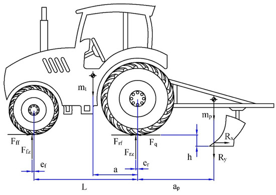
Figure 1.
Longitudinal plane stress analysis of tractor ploughing unit.
Among it, mt and mp represent the masses of the tractor and the moldboard plow, respectively, kg; Td is the torque applied to the tractor’s driving wheels, N·m; Fff and Frf denote the rolling resistance acting on the front and rear wheels of the tractor, respectively, N; Ffz and Frz are the vertical loads on the front and rear wheels of the tractor, respectively, N; Fq is the traction force exerted by the tractor, N; rf and rr are the rolling radii of the front and rear wheels, respectively, m; ef and er represent the offsets between the tire centers and the ground contact points of the front and rear wheels of the tractor, respectively, m; L is the distance between the front and rear axles, m; ap is the distance from the centroid of the moldboard plow to the center of the tractor’s rear axle, m; Rx and Ry are the horizontal and vertical components of the plowing resistance acting on the moldboard plow, respectively, N. The horizontal plowing resistance can be described by the Goryachkin’s formula [17], while the vertical component is typically considered to be 0.3 times the horizontal resistance. The expressions are as follows:
Among it, G is the gravitational force acting on the plow, N; f is the comprehensive soil friction coefficient, typically ranging from 0.3 to 0.5; k is the static resistance coefficient (soil-specific resistance), with values generally between 2 and 7 N/cm2; b is the working width of a single moldboard plow, cm; h is the tillage depth, cm; ε is the dynamic resistance coefficient, usually between 250 and 400 N·s2/m4; v is the travel speed, m/s.
2.1.1. Tractor Dynamic Vertical Load Model
Based on the longitudinal force analysis of the tractor established above, and considering the vertical load transfer that occurs on the tractor wheels during the plowing operation, moment equations are derived by taking moments about the front and rear wheel contact points A and B, respectively. The resulting moment equilibrium relationships are expressed as follows:
The dynamic vertical loads on the tractor’s front and rear wheels can be expressed as follows:
2.1.2. Tire-Soil Traction Model
Unlike the ground conditions encountered by automobiles, the soft soil surfaces in the field exhibit complex coupled interactions with tractor tires. The interaction between the soil and tires directly affects the tractor’s traction performance; therefore, it is necessary to establish a load model between the tractor tires and the soil. The Brixius equation, which uses the soil cone index as a single parameter to characterize this relationship, has been widely applied to describe the force interaction between wheels and soil. It is expressed as follows [18,19,20]:
Among it, Bn is the tire mobility index; s represents the wheel slip ratio; Fz is the vertical load on the tire, N. The tire mobility index Bn is expressed as
Among it, CI is the soil cone index; b is the tire section width, m; ht is the tire section height, m; Δd is the radial deformation of the tire, m; d is the tire diameter, m.
The rolling resistance of tractor tires is influenced by the tire’s inflation pressure, stiffness, and the firmness of the ground surface. Generally, the rolling resistance can be estimated as follows:
Among it, MRRf and MRRr are the rolling resistance coefficients of the tires, which can be expressed as [21]
2.1.3. Dynamic Model of the Tractor–Plow Tillage System
Based on the force analysis of the tractor–plow tillage system described above, a dynamic model of the tractor–plow tillage system is established by considering the parameter relationships among various components. Considering the longitudinal force equilibrium on the tractor’s longitudinal plane and the rotational torque equilibrium of the driving wheels, the dynamic model of the tractor–plow tillage system can be expressed as follows:
By simultaneously solving Equations (2)–(8), we obtain
Among it, Te is the torque output of the tractor engine, N·m.
2.2. Design of a Coordinated Control System for Tillage Depth and Vehicle Speed
2.2.1. Optimization of Coordinated Control Objective Decision Based on Optimal Overall Efficiency and Economy
Compared to automobiles, which generally use fuel consumption as the primary performance evaluation metric, the overall performance evaluation system for tractors is more comprehensive and complex. From an economic perspective, the performance requirement for tractors is to minimize costs, namely fuel consumption, while meeting the required operation quality. From the production operation perspective, the goal is to maximize operational efficiency while ensuring the required work quality.
In summary, the ideal operational mode for tractors is to meet both high efficiency and low fuel consumption demands under the premise of guaranteed operation quality. Therefore, this study develops a comprehensive evaluation index for tractor overall efficiency and economy based on both efficiency and economic considerations.
Traction efficiency refers to the ratio of the tractor’s tractive power to the effective power output of the engine. When the tractor engine power output is constant, traction efficiency can be used to reflect the overall efficiency of the tractor. Tractor traction efficiency can be expressed as
Among it, ηt denotes the tractor’s transmission efficiency; ηf represents the rolling efficiency; and ηs stands for the slip efficiency of the tractor.
The tractor’s transmission efficiency is related to its transmission mechanism and remains constant when the tractor speed is fixed. The tractor’s rolling efficiency can be expressed as
The tractor’s slip efficiency can be represented by the slip ratio as follows:
By combining Equations (4) and (10)–(12), the tractor’s traction efficiency can be expressed as
Tractors typically use the fuel consumption rate as an economic performance indicator. The fuel consumption rate is defined as the amount of fuel consumed, in kilograms, per hour for each kilowatt of power output by the tractor. The tractor’s fuel consumption rate can be expressed as
Among it, PT is the tractor’s tractive power during operation; Pe is the engine output power; and ge is the engine fuel consumption rate, which can be obtained by polynomial fitting based on engine speed and torque test data, g·kW−1·h−1.
Engine speed and torque can be expressed as functions of load and vehicle speed:
According to Equations (13) and (14), the tractor’s traction efficiency and fuel consumption rate are not mutually exclusive. Therefore, these two metrics can be combined. When the tractor meets the operation quality requirements, a higher traction efficiency coupled with a lower fuel consumption rate indicates better overall working performance of the tractor.
A comprehensive evaluation index for the tractor’s overall efficiency and economy, denoted as I, is introduced, defined as the ratio of traction efficiency to fuel consumption rate. Its mathematical expression is given by
According to Equations (10)–(16), the comprehensive evaluation index I for the tractor’s overall efficiency and economy can be expressed as
From the above equation, when the tractor’s tillage depth and soil resistance are fixed, a corresponding vehicle speed can be found such that the tractor operates at the optimal slip ratio, ensuring the best comprehensive performance of overall efficiency and economy. Therefore, the following objective function is proposed:
Among it, hmin and hmax represent the minimum and maximum working depths for the tractor model, m; vmin and vmax denote the minimum and maximum tractor speeds under the working gear, m/s.
Taking tillage depth and soil specific resistance as input variables and tractor forward speed as the control parameter, a cyclic optimization algorithm was designed to perform exhaustive optimization calculations under varying tillage depths and soil resistances. The optimal target speed curves for the tractor under different operating conditions, representing the best comprehensive performance, are shown in Figure 2.
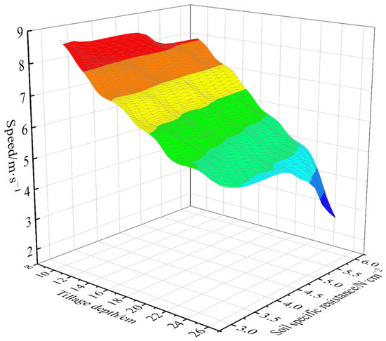
Figure 2.
The target speed curve with the best comprehensive performance.
2.2.2. Principle of Coordinated Control
During the tractor plowing operation, complex soil conditions often cause variations in the plowing resistance, which in turn affect the tire adhesion performance of the tractor. On one hand, this may lead to a reduction in tractor traction efficiency; on the other hand, it can cause severe damage to the field soil [22]. In traditional electro-hydraulic suspension systems of tractors, slip ratio control during plowing is usually achieved by adjusting the tillage depth, which often results in poor uniformity of the tillage depth.
Based on this, in order to improve tillage depth uniformity and tractor operational traction efficiency, a coordinated control strategy for tillage depth and vehicle speed is proposed. Aiming to optimize the comprehensive performance of overall tractor efficiency and economy, an optimal calculation is conducted to determine the target vehicle speed that achieves the best comprehensive efficiency-economic performance under different tillage depths and soil resistance conditions.
First, without altering the tractor’s tillage depth, the tractor speed is controlled by adjusting the engine driving torque through throttle control. Second, a minimum speed threshold is set; if the actual speed falls below this threshold during operation due to excessive resistance, the tillage depth is appropriately adjusted to bring the speed back within the preset threshold.
The overall principle of the tractor tillage depth and vehicle speed coordinated control system is illustrated in Figure 3.
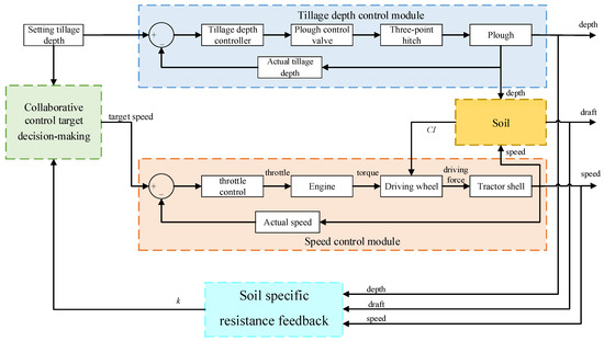
Figure 3.
Block diagram of the tractor tillage depth and speed coordinated control system.
2.3. Controller Design
2.3.1. Design of Tillage Depth Controller Based on Global Sliding Mode
The tractor electro-hydraulic suspension depth control system includes an electro-hydraulic proportional valve, a control hydraulic cylinder, a suspension device, and sensing components. The equivalent mathematical model of the depth control system is established as follows [23,24]:
where a0, b0, b1, and b2 are dynamic system coefficients. a0 ranges from 0.25 to 0.32; b0 ranges from 0.01 to 0.2; b1 ranges from 6 to 8; and b2 ranges from 3.5 to 4.
Based on preliminary bench tests and parameter identification results, the model parameters of the hydraulic depth control system were found to be non-constant and exhibit significant uncertainty under varying load conditions. To address this issue, we introduced the Global Sliding Mode Control (GSMC) algorithm from Reference [25], which is well-suited for systems with uncertainties. This approach enhances system performance by improving robustness against model parameter variations.
By transforming Equation (20), we obtain:
Select the system state variables
The system state equation is obtained as
Let the input position command be r. Then, the global dynamic sliding surface is designed as
The global sliding mode control law is designed as
Among it, uc is the linear control term; uvss is the switching term.
The linear control law is
The switching term in the control law is designed as
where the gain term ε can be expressed as
The Lyapunov function is defined as
Therefore, the control system is stable, and the system’s sliding mode exists and can be reached within a finite time.
2.3.2. Design of a Sliding Mode Variable Structure Speed Controller
The tractor-plow system is a typical strongly coupled and nonlinear system, where the travel speed and plowing depth interact with each other and are subject to disturbances from complex nonlinear factors such as soil resistance [26]. Given that sliding mode control is a mature and effective solution for managing nonlinear systems, this algorithm was selected for the design of the travel speed controller [27,28].
Let the target travel speed be vs, and the actual travel speed be va. The system output error and the rate of change in the error are defined as
According to the principle of the sliding mode variable structure control algorithm, the sliding surface is defined as
Among it, c is the sliding mode coefficient
Based on the previously established longitudinal force equilibrium dynamic equation of the tractor, the following expression is derived:
By taking the derivative of the sliding surface, we obtain
Sliding mode motion consists of two phases: the reaching phase and the sliding phase. According to the principle of sliding mode variable structure control, the reachability condition ensures that the trajectory starting from any point in the state space can reach the switching surface in finite time. Therefore, a reaching law is needed to improve the dynamic performance during the reaching phase.
To mitigate system chattering, a saturation function is introduced to replace the sign function used in the ideal sliding mode. By improving the exponential reaching law, the exponential reaching law can be expressed as
where ε represents the rate at which the system state approaches the switching surface s = 0, and k denotes the convergence rate. Both ε and k are positive constants. The saturation function is defined as
By combining Equations (36) and (37), the control input is derived as
To analyze the stability of the control system, the Lyapunov function is defined as
Taking the time derivative of the Lyapunov function yields
It follows from the above equation that
Therefore, the control system is stable, and the system’s sliding mode exists and can be reached within a finite time.
2.4. Construction of the Experimental Platform
2.4.1. Structure and Principle of the Electro-Hydraulic Suspension Test Bench
The tractor electro-hydraulic suspension test rig consists of a host computer, a tillage depth control system, and a simulated loading system [29]. The overall physical layout is shown in Figure 4.
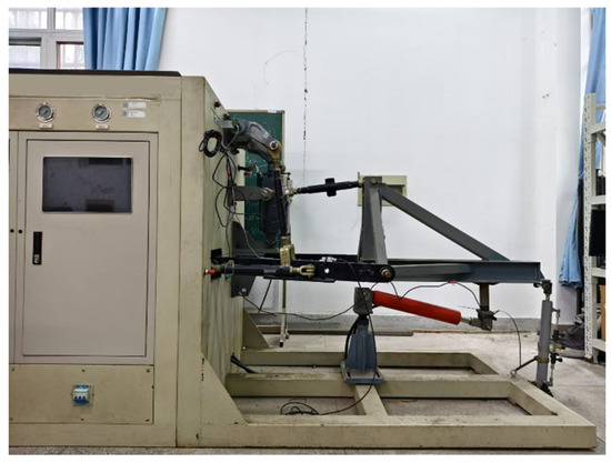
Figure 4.
Overall View of the Test Bench.
The host computer is used to establish the human–machine interface, enabling information interaction throughout the entire test rig.
The tillage depth control system mainly consists of a motor (Anhui WanNan Electric Machine Co., Ltd., Xuancheng, Anhui, China), a hydraulic pump (YOUYAN Electric Co., Ltd., Hangzhou, China), a controller(EPEC Oyj, Sastamala, Finland), a tillage control valve block (Ningbo Doyer Hydraulic Co., Ltd., Ningbo, Zhejiang, China), a lift cylinder (Shanghai Lixin Hydraulic Co., Ltd., Shanghai, China), an experimental plow frame, a tillage depth sensor (Shenzhen Pandauto Technology Co., Ltd., Shenzhen, Guangdong, China), and a draft force sensor (Bengbu Dayang Sensing Technology Engineering Co., Ltd., Bengbu, Anhui, China), with the system hardware configuration shown in Figure 5. Among these components, the motor and oil pump serve as the power unit, providing a high-pressure power source for the tillage depth control system. The controller receives the target control values set via the human–machine interface on one hand, and on the other hand, obtains real-time feedback of the actual tillage depth and plowing resistance from the tillage depth position sensor and the plowing resistance sensor. Based on this information, the controller calculates the control signal and sends it to the plowing control valve block. The valve block adjusts the system flow according to the received control signal, thereby driving the lifting cylinder to raise or lower the test plow frame.
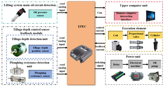
Figure 5.
The hardware structure diagram of the tillage depth control system.
The simulated loading system mainly consists of a motor (Anhui WanNan Electric Machine Co., Ltd., Xuancheng, Anhui, China), a hydraulic pump (YOUYAN Electric Co., Ltd., Hangzhou, China), a controller (Beijing Art Technology Co., Ltd., Beijing, China), an electro-hydraulic proportional relief valve (Beijing Huade Hydraulic Industrial Group Co., Ltd., Beijing, China), a loading cylinder (Shanghai Lixin Hydraulic Co., Ltd., Shanghai, China), a damping cylinder (Shanghai Lixin Hydraulic Co., Ltd., Shanghai, China), and a load sensor (Bengbu Dayang Sensing Technology Engineering Co., Ltd., Bengbu, Anhui, China), with the system hardware configuration shown in Figure 6. Similarly, a motor-driven oil pump is used as the power source. A dual-cylinder loading scheme based on the loading cylinder and damping cylinder is designed to simulate both steady-state and dynamic resistance encountered in field conditions.
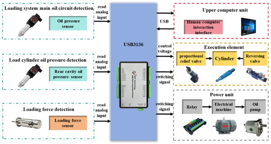
Figure 6.
The hardware structure diagram of the loading control system.
Operators can set the working conditions (such as working width, soil specific resistance, and vehicle speed) through the human–machine interface. During the tillage depth control process, the current target loading force is calculated and adjusted based on the actual tillage depth and the preset working condition parameters.
The controller receives the target loading force calculated from the human–machine interface, and simultaneously obtains real-time feedback of the actual loading force from the loading force sensor. It then computes the control signal and sends it to the electro-hydraulic proportional relief valve. According to the received control signal, the valve adjusts the pressure in the loading oil circuit, thereby controlling the loading force.
2.4.2. Construction of a Hardware-in-the-Loop Tillage Depth and Vehicle Speed Coordinated Control Platform Based on CAN Communication
Since the test rig only includes the tractor electro-hydraulic suspension system and lacks the complete vehicle and engine components, this study establishes tractor vehicle and engine models in MATLAB/Simulink R2022a. Using the Real-time and CAN Communication modules in MATLAB/Simulink, a hardware-in-the-loop real-time control system platform based on CAN communication is implemented.
The tractor vehicle and engine models read the tillage depth and plowing resistance signals from the electro-hydraulic suspension test platform in real time via the CAN bus. This enables throttle control and outputs feedback signals such as vehicle speed and slip ratio back to the electro-hydraulic suspension test platform.
The hardware composition and signal communication of the entire control platform are shown in Figure 7 and Figure 8.
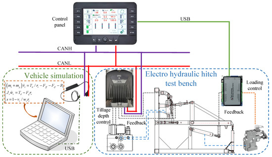
Figure 7.
Hardware composition of collaborative control platform.
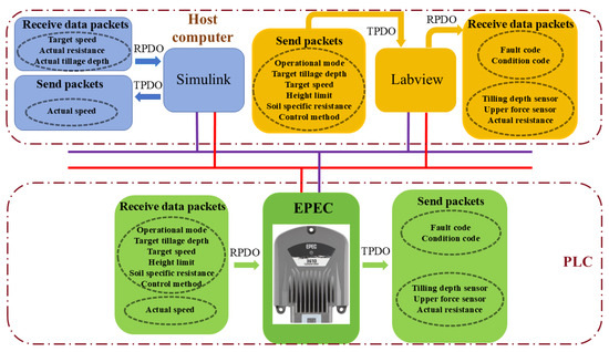
Figure 8.
Signal communication of coordinated control platform.
2.4.3. CAN Communication Signal Verification
Considering that data transmission between the modules of the developed hardware-in-the-loop control system platform is conducted via the CAN bus, it is necessary to verify the validity of the data on the CAN bus for each module [30]. In this study, a CAN analyzer was employed (KVASER Leaf Light v2 high-speed USB-CAN interface, Kvaser AB, Gothenburg, Sweden). The validity of data transmission and reception for each module was tested using the CANMOON 3.2.0.1 software provided with the EPEC controller.
2.4.4. Comparison Between Tillage Depth–Vehicle Speed Coordinated Control and Tillage Depth Control Methods Under Different Operating Conditions
To evaluate the impact of the coordinated depth–speed control method on the overall working performance of the tractor, comparative simulations and experiments were conducted against the single depth control method under full throttle conditions. The initial travel speed was set to 0 km/h with 100% throttle opening. In the simulation environment, the target plowing depth was set to 20 cm, while the mean soil specific resistance was designed to fluctuate continuously, increasing from 3 N/cm2 to 6 N/cm2 before gradually decreasing to 5 N/cm2. For the bench tests, different target plowing depths and varying ranges of random soil specific resistance were implemented, with the specific working conditions detailed in Table 1.

Table 1.
Test conditions.
3. Results and Discussion
3.1. CAN Bus Test Results
The vehicle simulation module, control panel, controller and CAN analyzer are connected to the same bus through KVASER CAN0, and the CAN analyzer is used to send the relevant status information of the operating unit, so as to verify the correctness of the display of the control panel. Change the operation mode and target input on the control panel to verify the correctness of the signal sent by the control panel; change the vehicle simulation signal to verify the correctness of the vehicle simulation module. The test results are shown in Table 2, and each unit can correctly receive and send the corresponding message information.
Table 2.
CAN communication signal verification results.
3.2. Comparison of Results Under Different Control Methods
As shown in Figure 9, the engine consistently outputs maximum torque when the tractor operates at full throttle. At a soil specific resistance of 3 N/cm2, the initial plowing resistance is relatively low. Under maximum engine torque, the tractor gradually accelerates. As the speed increases, the plowing resistance also rises until the driving force and resistance reach equilibrium, at which point the tractor stabilizes at an operating speed of 9 km/h. When the soil specific resistance increases from 3 N/cm2 to 6 N/cm2, the resulting rise in resistance causes the speed to decrease to 8 km/h. Conversely, when the soil specific resistance decreases from 6 N/cm2 to 5 N/cm2, the reduced resistance allows the speed to increase again. Since the engine output torque remains constant at full throttle and the plowing depth is fixed under the depth-only control strategy, fluctuations in load directly lead to variations in tractor speed. Furthermore, due to the lack of load matching, slip losses are significant, with an average slip ratio of 30.1% observed. In contrast, the coordinated depth-speed control method dynamically adjusts the travel speed to the optimal level in response to changes in soil specific resistance. As a result, the average slip ratio is effectively reduced and stabilized at 16.1%.
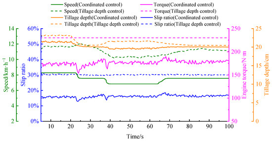
Figure 9.
Comparison of control performance among different methods under simulation conditions.
In terms of tillage quality, under the depth-only control method, the average plowing depth is 21.4 cm with a standard deviation of 0.94 cm, whereas under the coordinated control method, the average depth is 20.2 cm with a standard deviation of 0.63 cm. This indicates that the coordinated control method achieves smaller deviations from the target depth and significantly improved depth stability. Calculations show that the coordinated control method achieves an average traction efficiency of 72.2%, representing a 19.1% improvement over the full-throttle depth control method. The average fuel consumption rate is 358.3 g·(kW·h)−1, a reduction of 10.8% compared to the full-throttle mode. The comprehensive efficiency-economy index reaches 0.2, reflecting a 33.5% enhancement over the full-throttle operating mode.
As shown in Figure 10, under low-load operating conditions, the tractor delivers a maximum torque of 230 N·m at full throttle, resulting in an accelerating tendency. Once the actual tillage depth reaches the target value, the average operating speed stabilizes at 10.4 km/h. However, due to the suboptimal matching between engine output torque and draft resistance, the drive wheels exhibit significant slippage, with an average slip ratio of 28.6%. In contrast, the proposed depth–speed coordinated control method dynamically matches the engine torque with the draft resistance according to the current operating conditions. By coordinating speed regulation with depth adjustment, the average slip ratio is effectively reduced and stabilized at 12.7%, thereby improving traction performance.
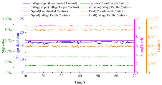
Figure 10.
Comparison of Control Performance Among Different Methods in Bench Testing Condition 1.
In terms of tillage quality, the standard deviation of tillage depth is 0.21 cm under depth-only control and 0.23 cm under coordinated control, indicating that both methods maintain satisfactory uniformity under low-load conditions. Furthermore, as presented in Table 3, compared with the conventional depth control method at full throttle, the proposed coordinated control method improves traction efficiency and overall efficiency–economic performance by 23.1% and 50.0%, respectively, while reducing the fuel consumption rate by 10.3%.
Table 3.
Tractor performance comparison under different control methods.
As shown in Figure 11, under medium-load operating conditions, the engine delivers the same maximum torque at full throttle. However, the increased target tillage depth and higher soil specific resistance lead to a greater draft load. Consequently, under depth-only control, the tractor exhibits reduced speed and increased slip, with an average operating speed of 9.1 km/h and an average slip ratio of 30.1%. Compared with low-load conditions, the speed decreases by 12.5%, while the slip ratio increases by 5.2%. In contrast, the proposed depth–speed coordinated control method dynamically matches the target depth with soil resistance, optimizing the operating speed to 5.8 km/h and significantly reducing the average slip ratio to 13.4%.
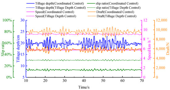
Figure 11.
Comparison of Control Performance Among Different Methods in Bench Testing Condition 2.
In terms of tillage quality, the standard deviations of tillage depth are 1.0 cm under depth-only control and 1.2 cm under coordinated control, indicating that depth-only control provides slightly better uniformity under these conditions. Nevertheless, as summarized in Table 3, compared with the conventional depth control method at full throttle, the proposed coordinated control method improves traction efficiency and overall efficiency–economic performance by 22.7% and 33.0%, respectively, while reducing the fuel consumption rate by 9.7%.
As shown in Figure 12, under heavy-load operating conditions, the increasing draft demand causes a notable performance decline as the tillage depth approaches the target value. With depth-only control at full throttle, the tractor achieves an average speed of 7.9 km/h and an average slip ratio of 31.6%. Compared with the medium-load condition, the operating speed further decreases by 13.2%, while the slip ratio increases by 4.9%. In contrast, the proposed depth–speed coordinated control method regulates the tractor speed to 5.04 km/h and significantly reduces the average slip ratio to 14.3%.
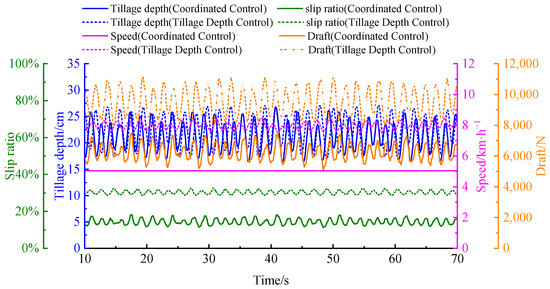
Figure 12.
Comparison of Control Performance Among Different Methods in Bench Testing Condition 3.
In terms of tillage quality, the standard deviations of tillage depth under depth-only control and coordinated control are 3.1 cm and 2.6 cm, respectively. This indicates that under high load fluctuations, coordinated control provides better depth stability and achieves higher tillage quality compared with depth-only control. Furthermore, as presented in Table 3, under heavy-load conditions, the proposed coordinated control method improves traction efficiency and overall efficiency–economic performance by 22.1% and 26.6%, respectively, while reducing the fuel consumption rate by 7.1% compared with the conventional depth control method at full throttle.
In summary, the coordinated tillage depth–travel speed control method proposed in this paper significantly outperforms the full-throttle tillage depth control method. Across various operating conditions, it meets operational quality requirements while simultaneously optimizing the overall working performance of the tractor, demonstrating superior adaptability.
4. Conclusions
To enhance the overall performance of tractors and reduce fuel consumption, this paper proposes a coordinated control method for regulating tillage depth and travel speed. By introducing a comprehensive performance evaluation index that integrates tractor efficiency and economic performance, the coordinated control objectives are optimized for different tillage depths and soil resistance conditions. A global sliding mode controller for depth control and a sliding mode variable structure controller for speed control were designed. Based on an indoor test platform for the tractor’s electro-hydraulic hitch system, a hardware-in-the-loop simulation platform for depth-speed coordinated control was established using CAN communication. The proposed control method was experimentally validated on this platform.
Experimental results under different operating conditions show that the single depth control method under full throttle suffers from excessive slip ratios and inadequate power-resistance matching. As the operational load increases, the slip ratio rises from 28.6% to 30.1% and further to 31.6%. In contrast, the proposed depth-speed coordinated control method dynamically adjusts operational parameters based on tillage depth and soil resistance, stabilizing the average slip ratio at 12.7%, 13.4%, and 14.3%, which is significantly lower than that of the single depth control method. In terms of operational quality, both methods exhibit depth uniformity under low and medium load conditions. However, under heavy load conditions, the coordinated control method achieves a smaller standard deviation in tillage depth, indicating superior depth stability. Overall, compared to the single depth control method under full throttle conditions, the coordinated control method significantly improves traction efficiency and overall tractor efficiency-economic performance across all three operating conditions, with maximum improvements of 23.1% and 50.0%, respectively. Furthermore, fuel consumption rates are reduced under all operating conditions.
In summary, the depth-speed coordinated control method proposed in this paper demonstrates excellent adaptability under various load conditions. It effectively reduces slip ratio, enhances traction efficiency, and improves overall tractor efficiency-economic performance, showcasing significant potential for engineering applications. In addition, this study still has certain limitations. Future work will focus on the following aspects: (1) developing a comprehensive kinematic model that incorporates both lateral and longitudinal degrees of freedom to accurately describe the motion states under complex field conditions, thereby enhancing the universality of the control strategy; (2) advancing the validation of the control strategy from hardware-in-the-loop test platforms to field tests with actual vehicles, so as to facilitate its application in agricultural production; and (3) exploring coordinated control methods under multi-parameter coupling mechanisms, with emphasis on the matching relationships among engine gear, throttle, and tillage depth, to maximize the operational performance potential of tractors.
Author Contributions
Conceptualization, X.S. and Z.L.; writing—original draft preparation, X.S.; writing—review and editing, X.S., Y.S. and X.D.; English language and style, X.S. All authors have read and agreed to the published version of the manuscript.
Funding
This research was funded by the National Key Research and Development Plan of China (Grant No. 2022YFD2001202) and Postgraduate Research and Practice Innovation Program of Jiangsu Province, China (Grant No. KYCX22_0716).
Institutional Review Board Statement
Not applicable.
Data Availability Statement
The original contributions presented in this study are included in the article. Further inquiries can be directed to the corresponding author.
Acknowledgments
The authors would like to thank all teachers and students for their invaluable support.
Conflicts of Interest
The authors declare no conflicts of interest.
References
- Mamkagh, A.M. Effect of soil moisture, tillage speed, depth, ballast weight and, used implement on wheel slippage of the tractor: A review. Asian J. Adv. Agric. Res. 2019, 9, 1–7. [Google Scholar] [CrossRef]
- Benkovic, R.; Sumanovac, L.; Jug, D.; Jug, I.; Japundzic-Palenkic, B.; Mirosavljevic, K.; Popijac, M.; Benkovic-Lacic, T. Influence of Aggregated Tillage Implements on Fuel Consumption and Wheel Slippage. Teh. Vjesn. Tech. Gaz. 2021, 28, 956–962. [Google Scholar]
- Anche, G.M.; Devika, K.B.; Subramanian, S.C. Robust Pitching Disturbance Force Attenuation for Tractor Considering Functional Constraints. IEEE Access 2020, 8, 86419–86432. [Google Scholar] [CrossRef]
- Shen, W.; Wang, J.H.; Huang, H.L.; He, J.Y. Fuzzy sliding mode control with state estimation for velocity control system of hydraulic cylinder using a new hydraulic transformer. Eur. J. Control 2019, 48, 104–114. [Google Scholar] [CrossRef]
- Singha, P.S.; Kumar, A.; Sarkar, S.; Baishya, S.; Kumar, P. Development of Electro-Hydraulic Hitch Control System through Lower Link Draft Sensing of a Tractor. J. Sci. Ind. Res. 2022, 81, 384–392. [Google Scholar] [CrossRef]
- Xu, J.K.; Li, R.C.; Li, Y.C.; Zhang, Y.S.; Sun, H.L.; Ding, X.K.; Ma, Y. Research on Variable-Universe Fuzzy Control Technology of an Electro-Hydraulic Hitch System. Processes 2021, 9, 1920. [Google Scholar] [CrossRef]
- Gupta, C.; Tewari, V.K.; Ashok Kumar, A.; Shrivastava, P. Automatic tractor slip-draft embedded control system. Comput. Electron. Agric. 2019, 165, 104947. [Google Scholar] [CrossRef]
- Zhang, S.; Wu, Z.B.; Chen, J.; Li, Z.; Zhu, Z.X.; Song, Z.H.; Mao, E.R. Control method of driving wheel slip rate of high-power tractor for ploughing operation. Trans. CSAE Trans. Chin. Soc. Agric. Eng. 2020, 36, 47–55. [Google Scholar]
- Zhao, G.Q.; Xia, Z.G. Research on Tractor Slip Rate Control Based on SimulationX. J. Agric. Mech. Res. 2021, 43, 240–245. [Google Scholar]
- Han, Z.R.; Yang, J.R.; Li, R.C.; Xu, X.Z.; Li, Y.C.; Li, N. Research on Tillage Depth Control Method of Double Parameters of Variable Target Slip Rate and Position. J. Agric. Mech. Res. 2023, 45, 246–252. [Google Scholar]
- Cui, D.D.; Cui, G.W.; Zhang, T. Research on adaptive variable weight factor of electric control hydraulic lifting system for agricultural machinery equipment. Mach. Tool Hydraul. 2024, 52, 115–122. [Google Scholar]
- Zhang, S.L.; Ren, W.; Xie, B.; Luo, Z.H.; Wen, C.K.; Chen, Z.J.; Zhu, Z.X.; Li, T.H. A combined control method of traction and ballast for an electric tractor in ploughing based on load transfer. Comput. Electron. Agric. 2023, 207, 107750. [Google Scholar] [CrossRef]
- Wang, Q.; Wang, X.; Wang, W.; Song, Y.L.; Cui, Y.J. Joint control method based on speed and slip rate switching in plowing operation of wheeled electric. Comput. Electron. Agric. 2023, 215, 108426. [Google Scholar] [CrossRef]
- Kumari, A.; Raheman, H. Tillage operation with a tractor drawn rotavator using an embedded advisory system for minimizing fuel consumption. J. Biosyst. Eng. 2023, 48, 487–502. [Google Scholar] [CrossRef]
- Li, X.Z.; Xu, L.Y.; Liu, M.N.; Yan, X.H.; Zhang, M.Z. Research on torque cooperative control of distributed drive system for fuel cell electric tractor. Comput. Electron. Agric. 2024, 219, 108811. [Google Scholar] [CrossRef]
- Shao, X.D.; Yang, Z.H.; Mowafy, S.; Zheng, B.W.; Song, Z.H.; Luo, Z.H.; Guo, W.J. Load characteristics analysis of tractor drivetrain under field plowing operation considering tire-soil interaction. Soil Tillage Res. 2023, 227, 105620. [Google Scholar] [CrossRef]
- Moitzi, G.; Haas, M.; Wagentristl, H.; Boxberger, J.; Gronauer, A. Energy consumption in cultivating and ploughing with traction improvement system and consideration of the rear furrow wheel-load in ploughing. Soil Tillage Res. 2013, 134, 56–60. [Google Scholar] [CrossRef]
- Sunusi, I.I.; Zhou, J.; Wang, Z.Z.; Sun, C.Y.; Ibrahim, I.E.; Opiyo, S.; Korohou, T. Intelligent tractors: Review of online traction control process. Comput. Electron. Agric. 2020, 170, 105176. [Google Scholar] [CrossRef]
- Brixius, W.; Wismer, R.D. Traction prediction equations for wheeled vehicles. In Proceedings of the John Deere Technical Report Release Conference, Moline, IL, USA, 7 July 1975. [Google Scholar]
- Brixius, W. Traction prediction equations for bias ply tires. Am. Soc. Agric. Eng. 1987, 9, 87–98. [Google Scholar]
- Zhao, J.H.; Zhao, T.L.; Xu, L.Y.; Li, Y.Y.; Zhang, J.Y.; Liu, Y.H.; Sun, L. General model building and experiment on traction performance prediction based on APSO algorithm. Trans. Chin. Soc. Agric. Mach. 2024, 55, 519–529. [Google Scholar]
- Wang, Q.; Wang, X.D.; Wang, W.; Zhang, S.; Cui, Y.J. Resistance adaptive operation control of electric tractor ploughing unit. J. Agric. Mech. Res. 2025, 47, 224–229. [Google Scholar]
- Sun, X.; Song, Y.; Wang, Y.; Qian, J.; Lu, Z.; Wang, T. Design and test of a tractor electro-hydraulic-suspension tillage-depth and loading-control system test bench. Agriculture 2023, 13, 1884. [Google Scholar] [CrossRef]
- Wang, S.Y.; Liu, Z.; Li, R.C.; Xu, J.K.; Liu, Y.J. Variable Weight Force-Position Mixed Control of High-power Tractor Based on Soil Specific Resistnce. Trans. Chin. Soc. Agric. Mach. 2018, 49, 351–357. [Google Scholar]
- Liu, J.K. Matlab Simulation for Sliding Mode Control, 1st ed.; Tsinghua University Press: Beijing, China, 2005; pp. 417–422. [Google Scholar]
- Aravind, K.; Paja, P.; Manuel, P. Task-based agricultural mobile robots in arable farming: A review. Span. J. Agric. Res. 2017, 15, e02R01. [Google Scholar] [CrossRef]
- Cho, W.K.; Yoon, Y.G.; You, S.H. A Study on Sway Stability Control Methods for Tractor-Trailer System Using Rear Wheel Steering. IEEE Access 2024, 12, 66952–66963. [Google Scholar] [CrossRef]
- An, Y.H.; Wang, L.; Deng, X.T.; Chen, H.; Lu, Z.X.; Wang, T. Research on Differential Steering Dynamics Control of Four-Wheel Independent Drive Electric Tractor. Agriculture 2023, 13, 1758. [Google Scholar] [CrossRef]
- Sun, X.X.; Lu, Z.X.; Song, Y.; Cheng, Z.; Jiang, C.X.; Qian, J.; Lu, Y. Development Status and Research Progress of a Tractor Electro-Hydraulic Hitch System. Agriculture 2022, 12, 1547. [Google Scholar] [CrossRef]
- Han, J.; Yan, X.; Tang, H. Method of controlling tillage depth for agricultural tractors considering engine load characteristics. Biosyst. Eng. 2023, 227, 95–106. [Google Scholar] [CrossRef]
Disclaimer/Publisher’s Note: The statements, opinions and data contained in all publications are solely those of the individual author(s) and contributor(s) and not of MDPI and/or the editor(s). MDPI and/or the editor(s) disclaim responsibility for any injury to people or property resulting from any ideas, methods, instructions or products referred to in the content. |
© 2025 by the authors. Licensee MDPI, Basel, Switzerland. This article is an open access article distributed under the terms and conditions of the Creative Commons Attribution (CC BY) license (https://creativecommons.org/licenses/by/4.0/).