1. Introduction
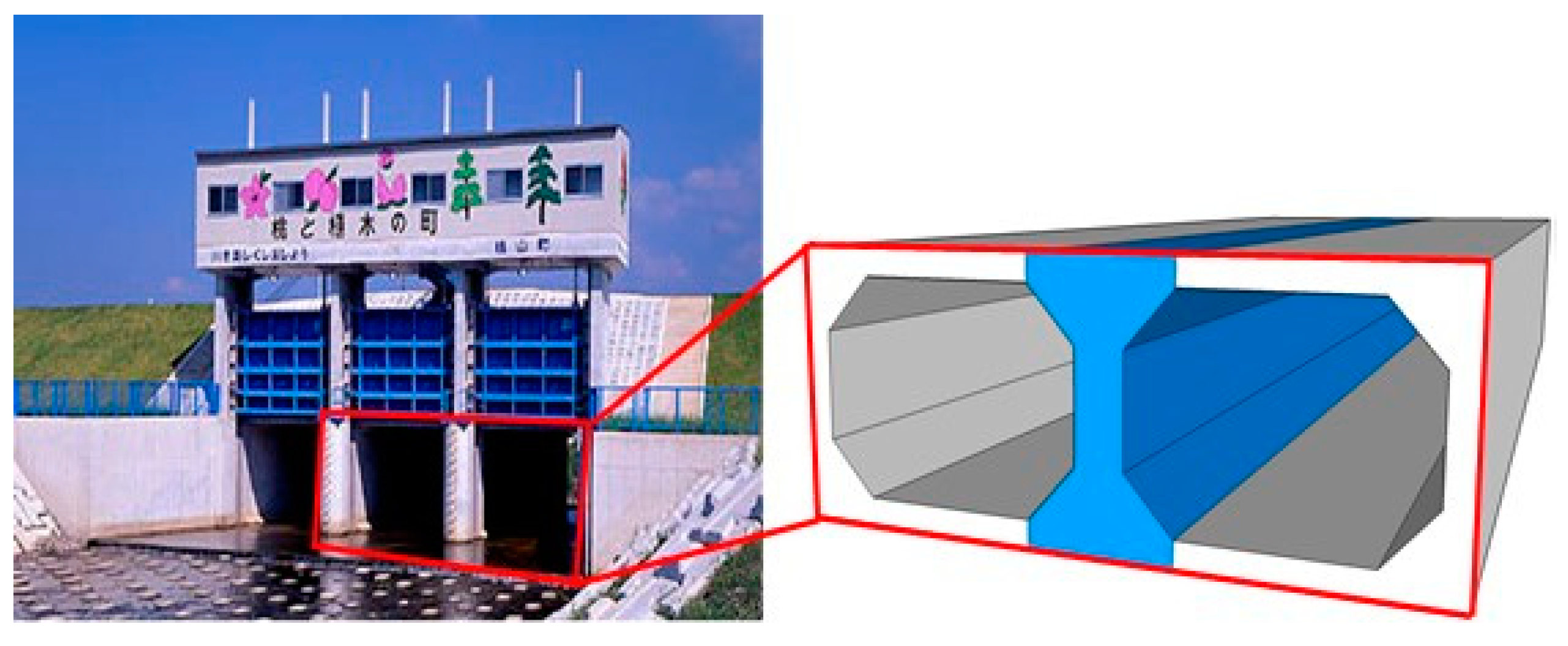
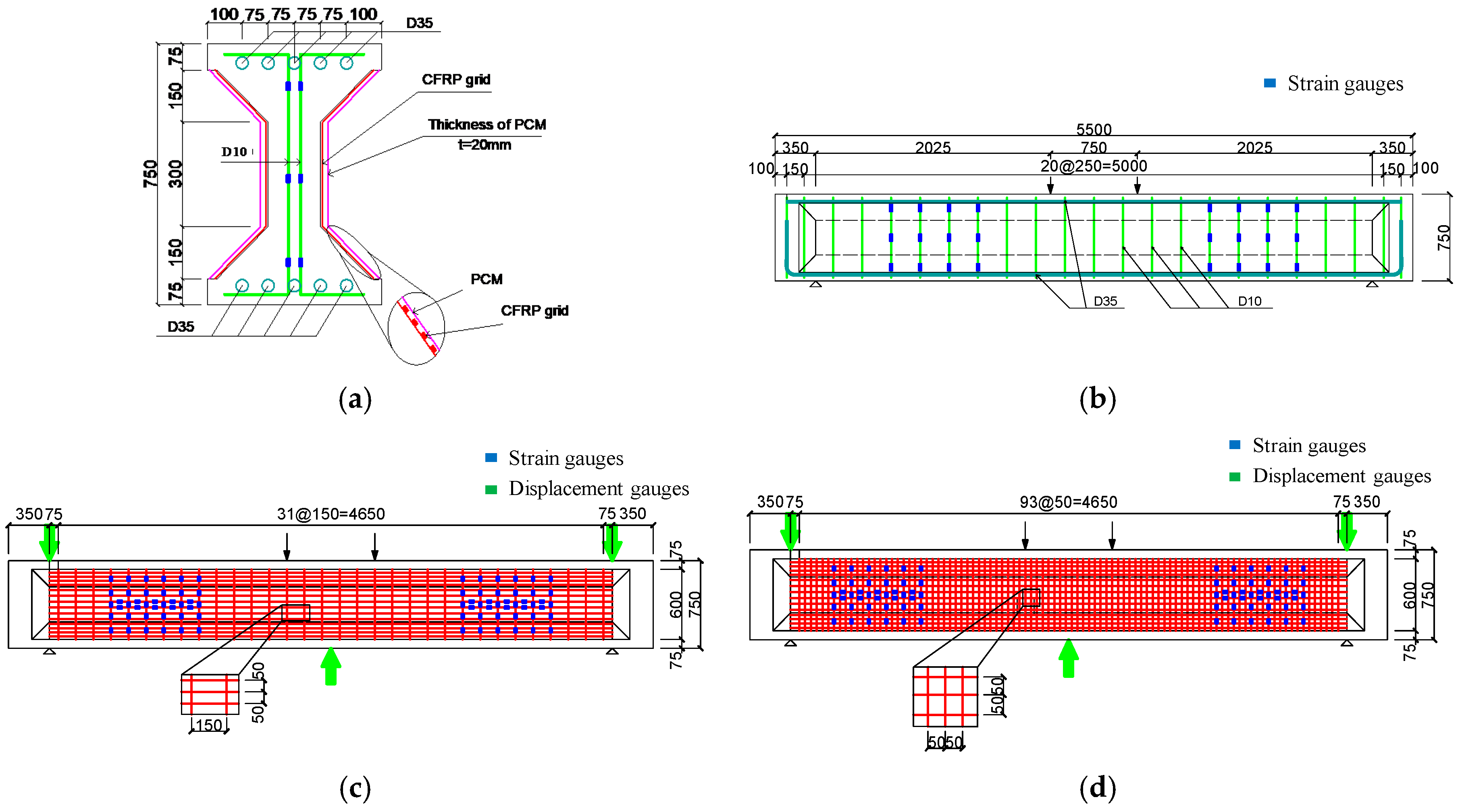
Over the last two decades, there has been a great demand for the strengthening or retrofitting of existing reinforced concrete (RC) structures due to ageing, the increment of the service load, the fact that they were designed using former guidelines, or even due to earthquakes. For example, a large number of concrete structures designed and constructed according to former standards had collapsed or were damaged in the Great East Japan Earthquake in 2011. At that time, a sluice with an I-shaped profile (
Figure 1), placed across a river embankment to drain wastewater and pump water from the river, was damaged due to the occurrence of uneven settlement. Moreover, it has been found that the steel reinforcement ratio of existing concrete structures designed using the former standard was inadequate. For this reason, a certain strengthening method is required to make sure the capacity of sluice is sufficient in shear. If using reinforced concrete to enlarge the cross section, the inhibition rate of the cross section becomes too large and a thicker concrete covering should be applied to prevent corrosion of steel bars. As a result, this method may have an adverse impact on the normal use of sluice, so another method should be used to instead of enlargement of the cross section.
Some strengthening and retrofitting materials have been developed for existing concrete structures in the last decade, including textile reinforced mortar (TRM) [
1,
2,
3,
4,
5,
6], fiber reinforced cementitious matrix (FRCM) [
7,
8,
9,
10,
11,
12], textile reinforced concrete (TRC) [
13,
14,
15,
16], steel-reinforced grout (SRG) [
17,
18], and fiber reinforced polymer (FRP) composites [
19,
20,
21,
22,
23,
24,
25]. Among them, fiber reinforced polymer (FRP) composites, including FRP sheets, FRP plates, FPR grids, and so forth, have been demonstrated to be an effective solution due to their favorable and prominent properties (e.g., light weight, high tensile strength, excellent corrosion resistance, and durability in harsh environments) [
26,
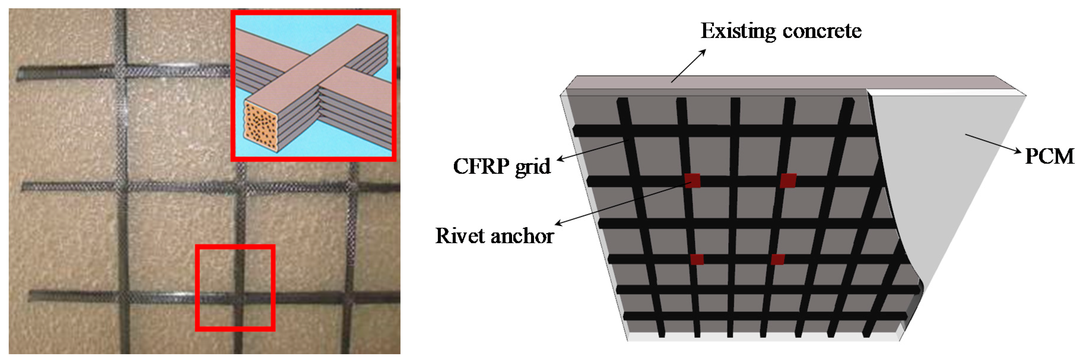
27]. FRP grids (
Figure 2), a kind of FRP composite that has been proposed in the past decade, are made of high-strength fibers such as carbon fibers impregnated with a suitable resin system to form a grid pattern, and the main difference between FRP grids and FRP sheets/plates include the production process, cross section, and stiffness. Currently, numerous experimental studies have been performed on RC beams strengthened with externally bonded FRP sheets/plates, but those were always conducted together with epoxy-based materials used as bonding agent. Thus, the strengthening effect in flexural or in shear largely depends on these organic systems (usually an epoxy system) at the bonding interface between FRP sheets/plates and the concrete substrate. However, the epoxy-based materials have their own weaknesses, which primarily include the poor fire resistance, easy degradation under strong UV radiation, and low efficiency in both over-high/low temperature and moisture environments [
28,
29,
30]. These disadvantages have partially compromised the attractive properties of strengthening techniques mentioned before in some engineering applications. For these reasons, the bonding behavior at the interface may deteriorate rapidly if existing concrete structures lie in harsh environments, such as over-high/low temperature, in the presence of moisture, or even near fire and underwater.
Therefore, some scholars have suggested replacing the epoxy systems with some inorganic cementitious materials to develop two major strengthening systems which combine FRP composites and cement-based materials [
31], namely FRP sheets/plates bonded with a cementitious material [
32] and FRP grids bonded with cement mortar [
33,
34]. Compared to the former strengthening method, the advantages of FRP grids bonded with a cement-based material are summarized as follows: (a) the stress transfer between the FRP grid and cementitious materials is more efficient, caused by the improving of the impregnation [
32,
35]; (b) the drawbacks observed with the FRP sheets/plates with respect to uneven pasting and empty drums can be effectively avoided, especially when the strengthening areas are excessively large; and (c) for FRP grid strengthening, the rivets are usually considered to be a temporary anchor to attach the FRP grid on the external surface of concrete beams such that better bonding at the interface may be obtained to some extent.
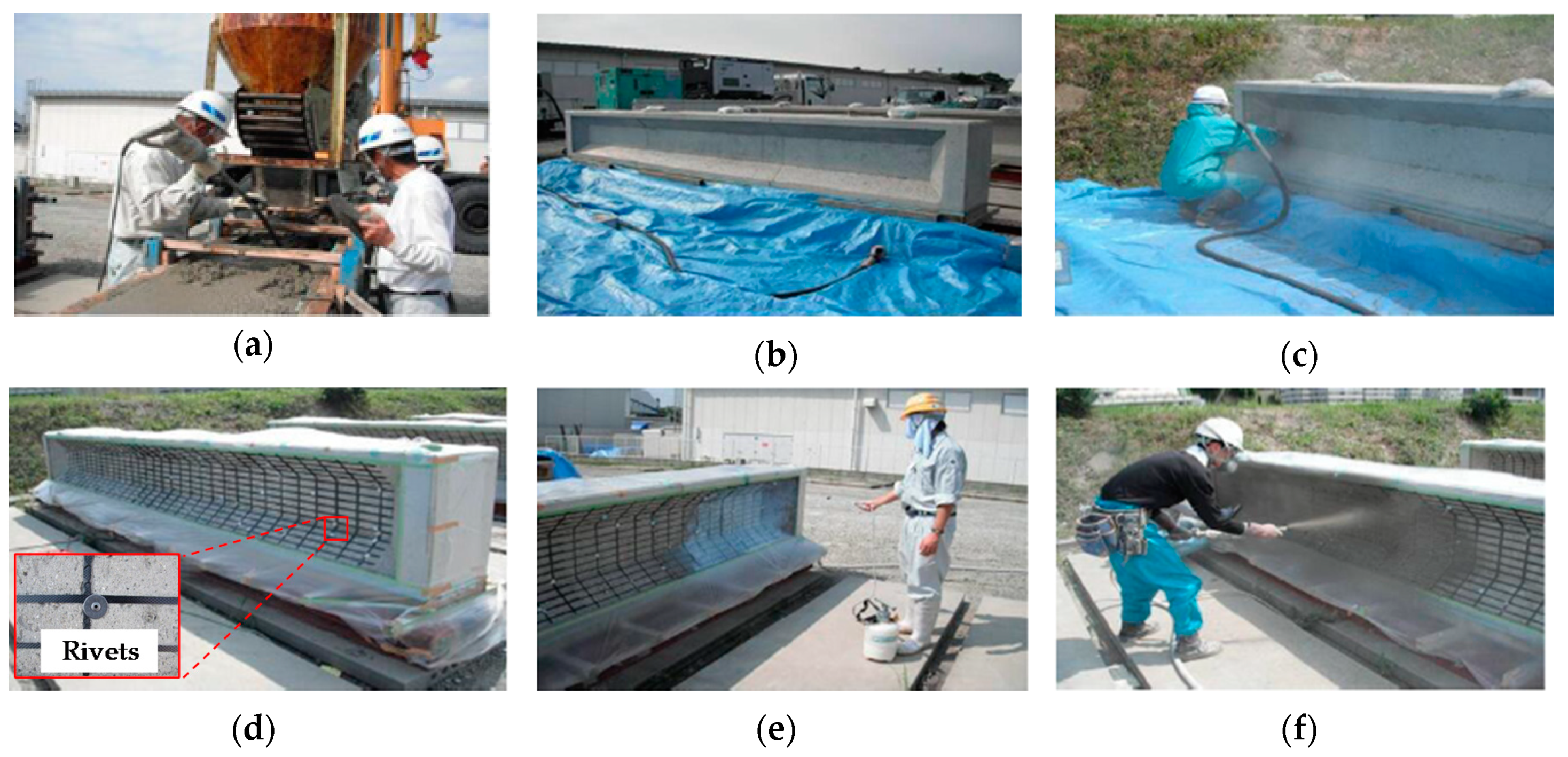
As mentioned before, FRP grids are usually fixed and bonded to concrete by spraying or laminating a thin covering of normal mortar. However, normal mortar is easily broken due to its properties of low tensile strength and brittleness. Thus, several cementitious materials used as a thin strengthening layer, such as engineered cementitious composite (ECC) matrix [
33,
34,
36] and polymer cement mortar (PCM) [
37,
38,
39], have been proposed by scholars from all over the world to take the place of normal mortar with low strength. PCM, a new inorganic material used in strengthening fields, is made by pouring a small volume of organic polymer (e.g., acrylic copolymer [
40], arene-perfluoroarene [
41,
42]) into a kind of cement mortar. The purpose of this is to improve the performance of the original inorganic materials, as it displays such properties as high tensile strength, superior corrosion and seepage resistance, lower incidence of dry cracking, as well as better bonding performance between PCM and the original concrete substrate [
37,
43,
44].
A large number of relative studies on various FRP composites in shear strengthening have been discussed in recent years. For example, Liu et al. and Koutas et al. [
6,
45,
46] demonstrated the current state of research regarding RC members retrofitted by CFRP grid-PCM layer, indicating that regardless of the flexural or shear reinforcement effect, the load-carrying capacity of RC members retrofitted by CFRP grid-PCM was adequate. Teng et al. [
47] summarized the development and application of new structural materials, such as FRP composites, showing that the load capacity and ductility of strengthened structures were increased compared to unreinforced structures. Chen et al. [
48] and Lu et al. [
49] considered that the debonding failure of FRP composites with various formations (e.g., FRP grids/sheets) usually appeared on the concrete surface prior to concrete crushing during the shear resistance process. Zheng et al. [
50] conducted several shear tests with RC beams externally bonded with FRP grid and UHTCC. The results showed that the shear strengthening effect produced by this method was very good, and studied the shear-compression failure and partial debonding of FRP grids regarding the ultimate state for these beam specimens with different reinforcement ratios. Ding et al. [
51] assessed the strengthening effect by comparing FRP grids and FRP sheets, indicating that the load-carrying ability and safety of beams reinforced with FRP grids were better than FRP sheets. In addition, Spadea et al. [
52] and Ferreira et al. [
53] noted that the structural effectiveness of FRP composites in strengthening RC members was quite important to predict the load capacity of the strengthened beams. Therefore, previous investigators have pointed out that the evaluation method, which determines the contribution of the FRP composites for RC beams in shear, should carefully consider the effective strain of the FRP composites [
54,
55,
56,
57]. However, existing calculated methods in shear are not suitable for the FRP grid because its stress transfer mechanism is different from traditional FRP composites (e.g., FRP sheets, FRP plates, and FRP bars). Moreover, at present, few studies have explored the reinforcement range and reinforcement amount of I-shaped RC beams, especially those strengthened by FRP grids.
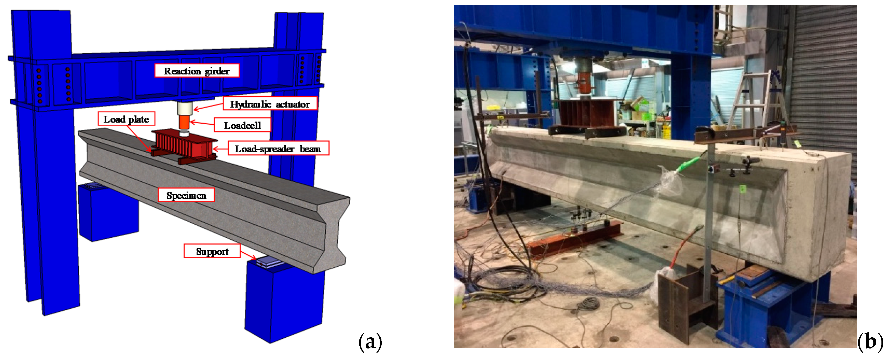
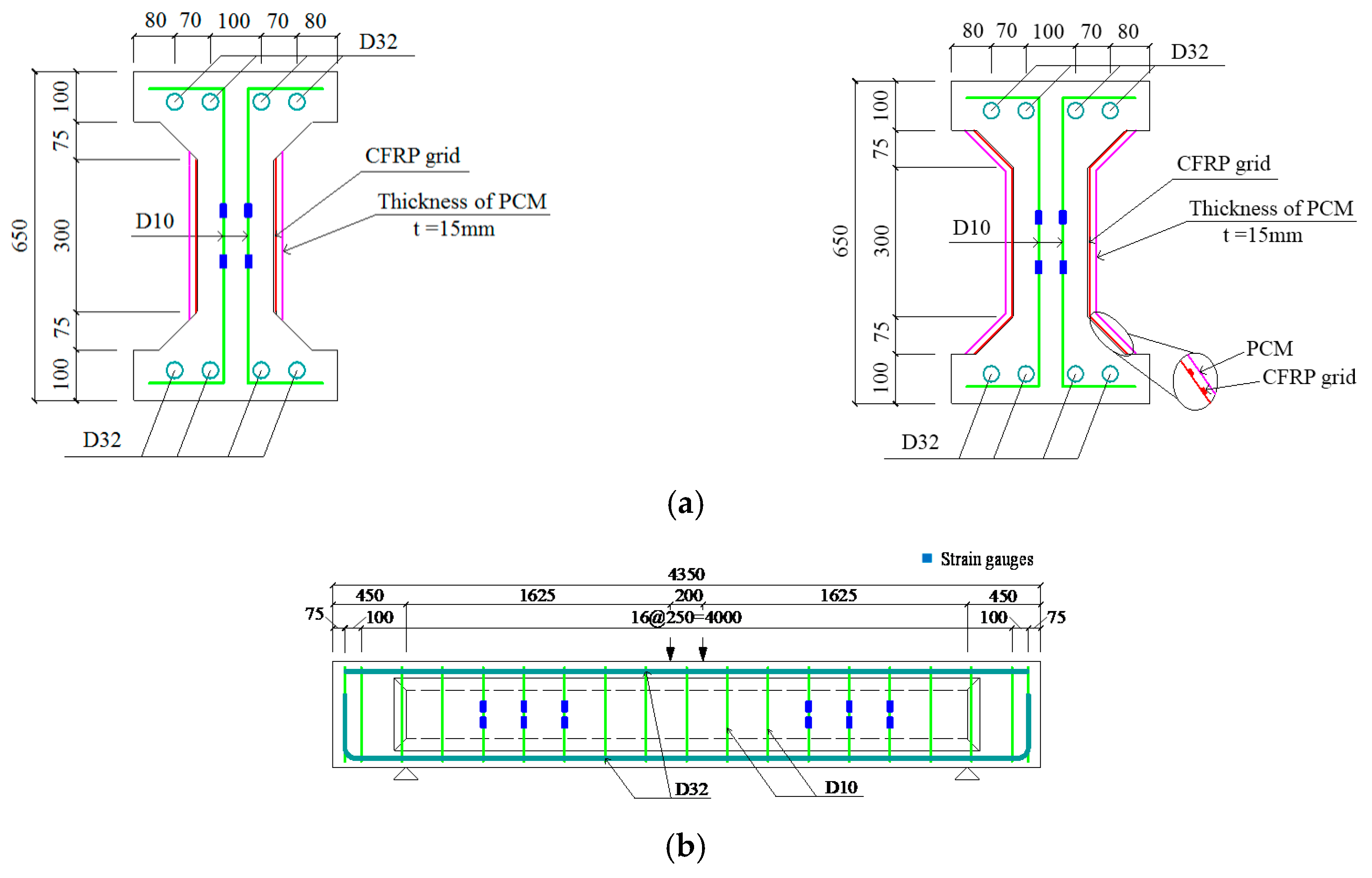
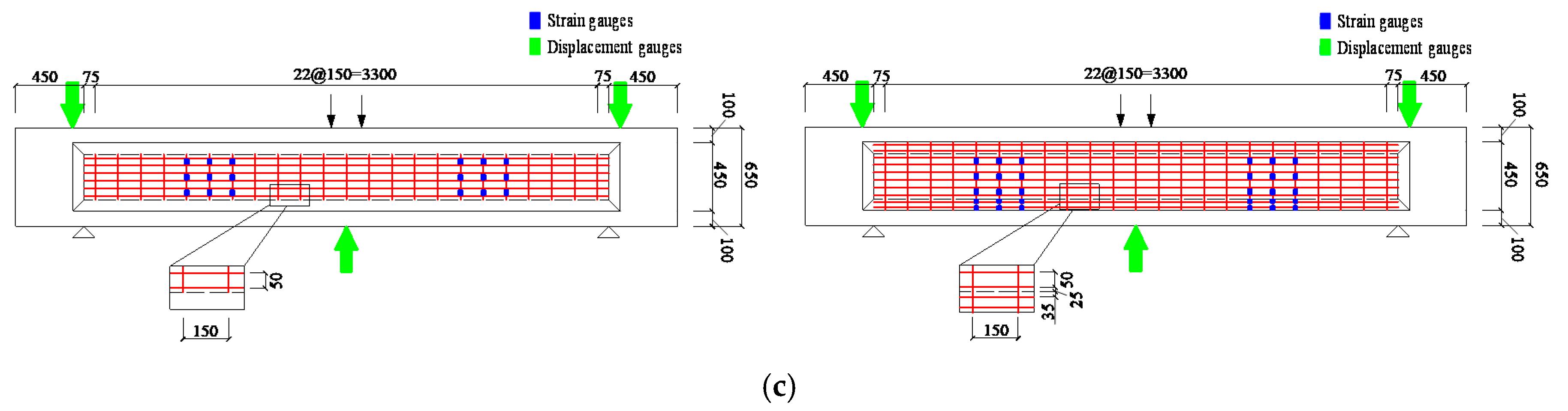
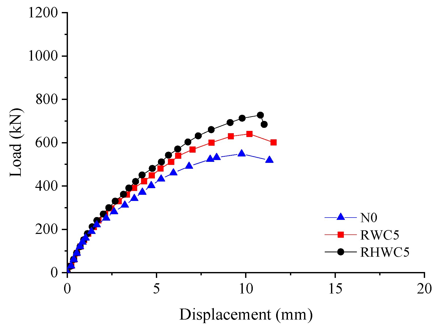
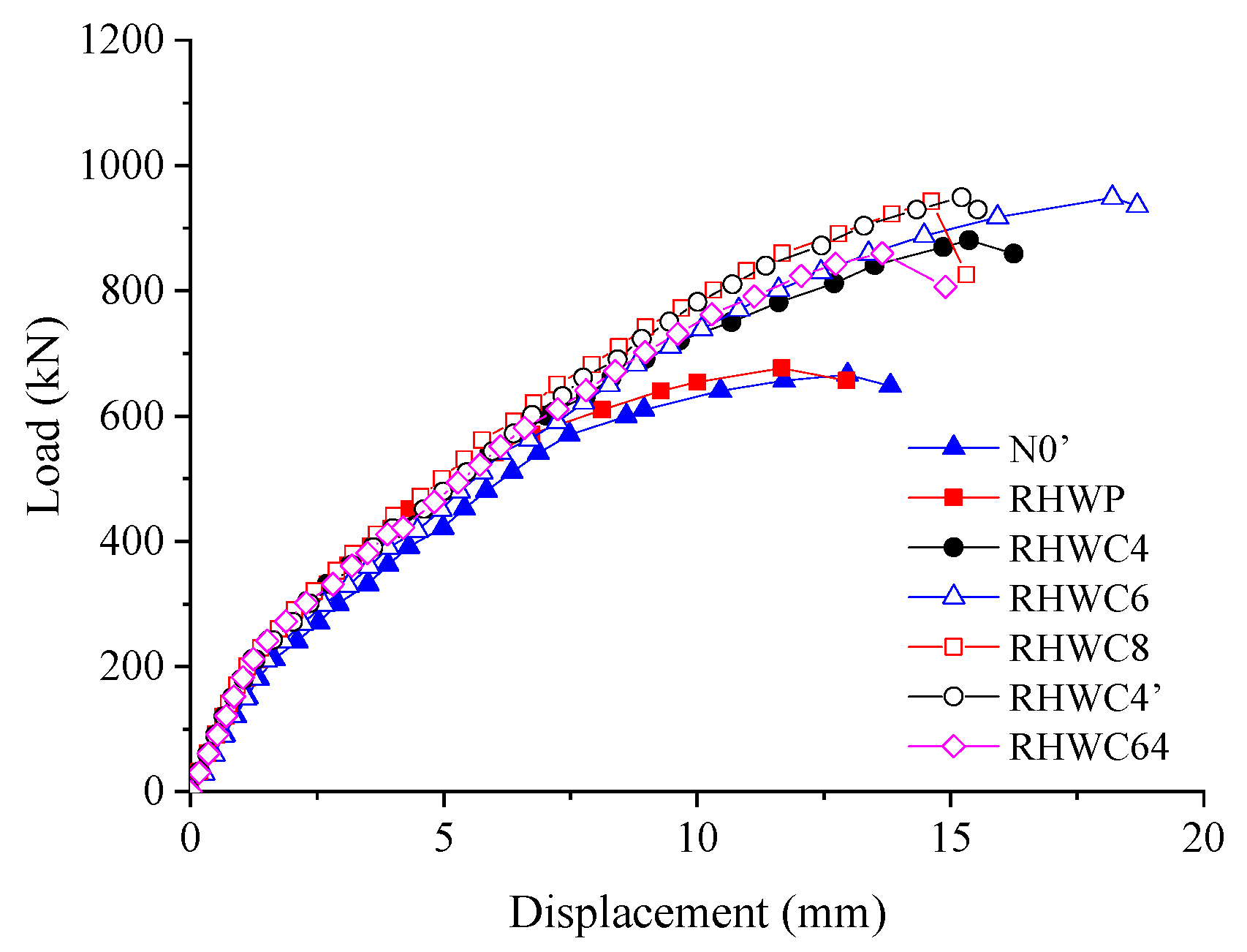
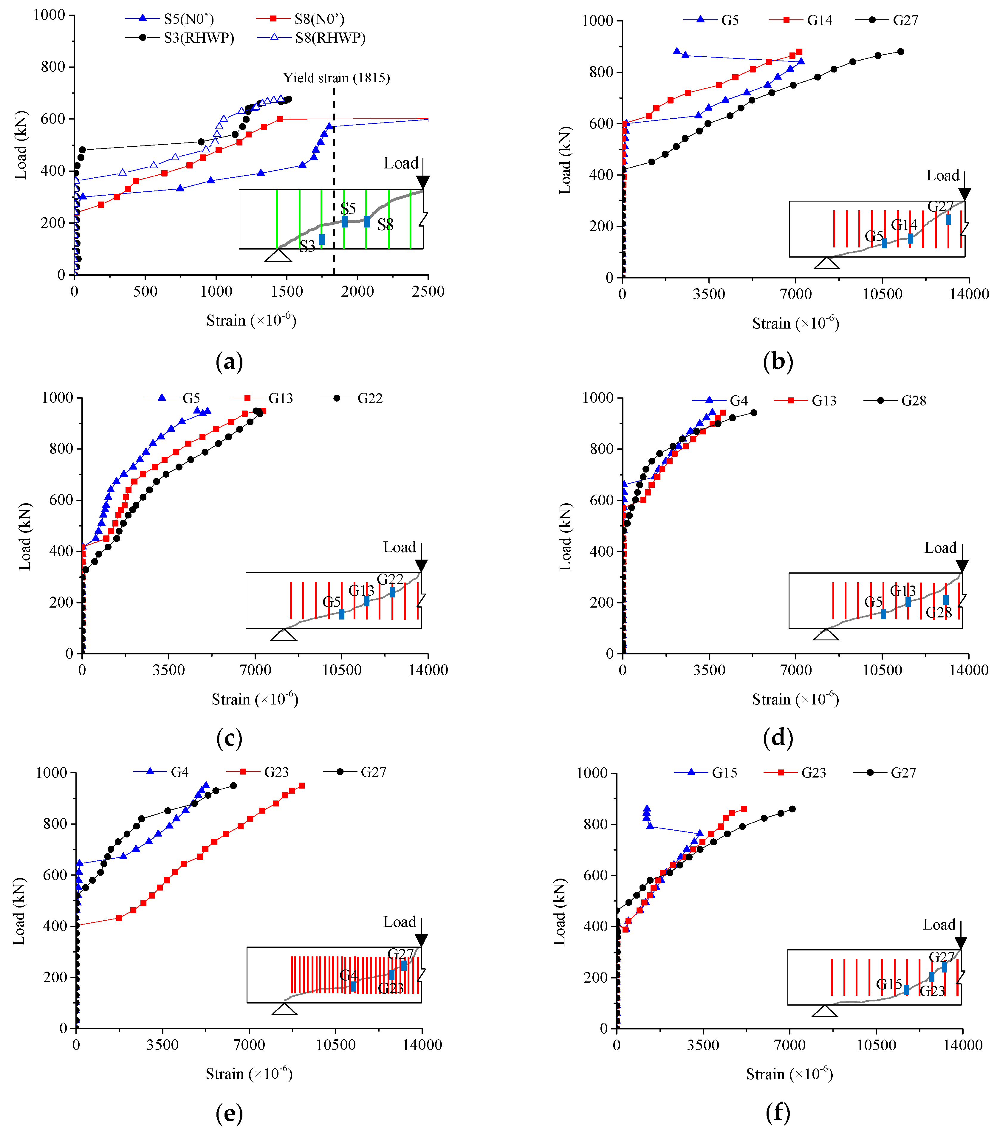
Taking the above background into consideration, this paper aims to explore the shear strengthening effect of RC beams with I-shaped profiles using FRP grid-PCM reinforcement layer. For this purpose, a total of ten beam specimens are divided into two series (called Series A and Series B later) and are introduced in different sections. Initially, three kinds of specimens (Series A) under various reinforcement ranges are used to investigate which type is the most suitable for RC beams with I-shaped profiles; then, based on the research results of Series A, the other series, Series B, are investigated in order to explore the shear resistance effect on concrete beams under different reinforcement amounts. The load–deflection responses, load–strain responses, and crack patterns are compared among all specimens. Moreover, a new evaluation method for the shear capacity of RC beams with a combination of CFRP grid and PCM as a reinforcement layer, which is based on the effective strain of the CFRP grid, is subsequently developed.
4. Analytical Model of Shear Capacity
To predict the shear capacity of RC beams with a CFRP-PCM reinforcement layer, the following Equation (3) is usually used as the analytical system to obtain the shear capacity of strengthened beams (
V), which is introduced by the Japan Road Association [
67], given as follows:
where
Vcon,
Vpcm,
Vst, and
Vg are defined as the shear resistance contribution of the concrete, PCM, stirrups, and CFRP grid, respectively. It should be pointed out that the design method of PCM on shear contribution is very similar to concrete, according to previous experiments together with standards suggested [
66,
67], and this corresponding equation for PCM hence would not appear over and over; rather, a small amount of difference would still be noted. All the mentioned parameters can be expressed as:
where
γb is defined as the reduction factor of member coefficient and the recommended value is equal to 1.00; while the calculation methods for
fvcd and for coefficients
βd and
βp are:
where
fc′ is defined as the design compressive strength of concrete or PCM;
ρw is calculated by the Equation (2), as well as
h0, both mentioned in
Section 2.1. The parameter
βn, depending on the bending moment and the stress produced by axial forces, has value
βn = 1, since in this study no prestress is introduced.
The stirrup contribution is given by:
where,
α is defined as the angle between the stirrups and the longitudinal direction of the member;
fy0 and
Aweb are defined as the yielding strength and cross-sectional areas in terms of internal stirrups here;
z is defined as the ratio of the effective depth to the constant value 1.15; and coefficient value
γb is equal to 1.15.
The CFRP grid contribution is given by:
where
and
E0 are defined as the cross-sectional areas and elastic modulus with respect to vertical FRP grids regarded as the shear reinforcement here;
αs is defined as the angle between the CFRP grid and transverse direction of the member;
εu is defined as the rupture strain of the CFRP grid;
sg is defined as the spacing of the vertical grids, which are generally considered as external stirrups for better understanding; and the coefficient value
γb is equal to 1.15.
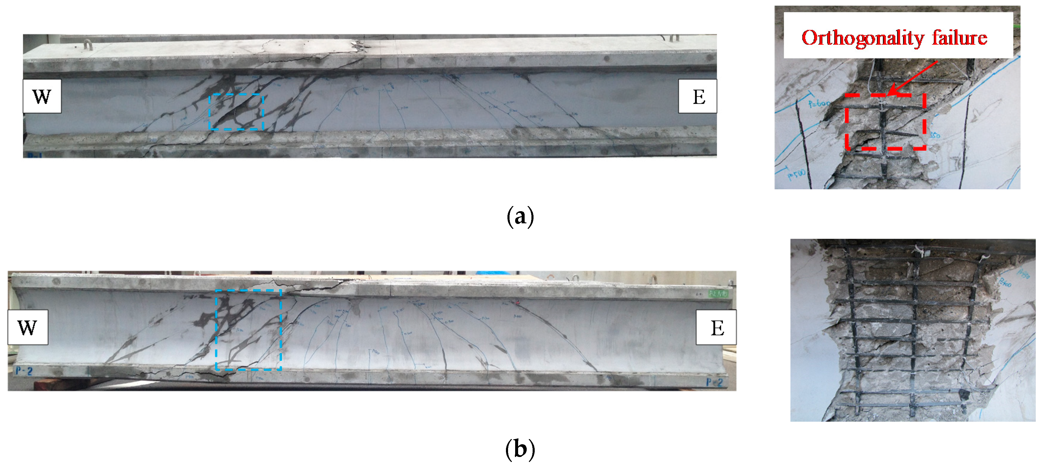
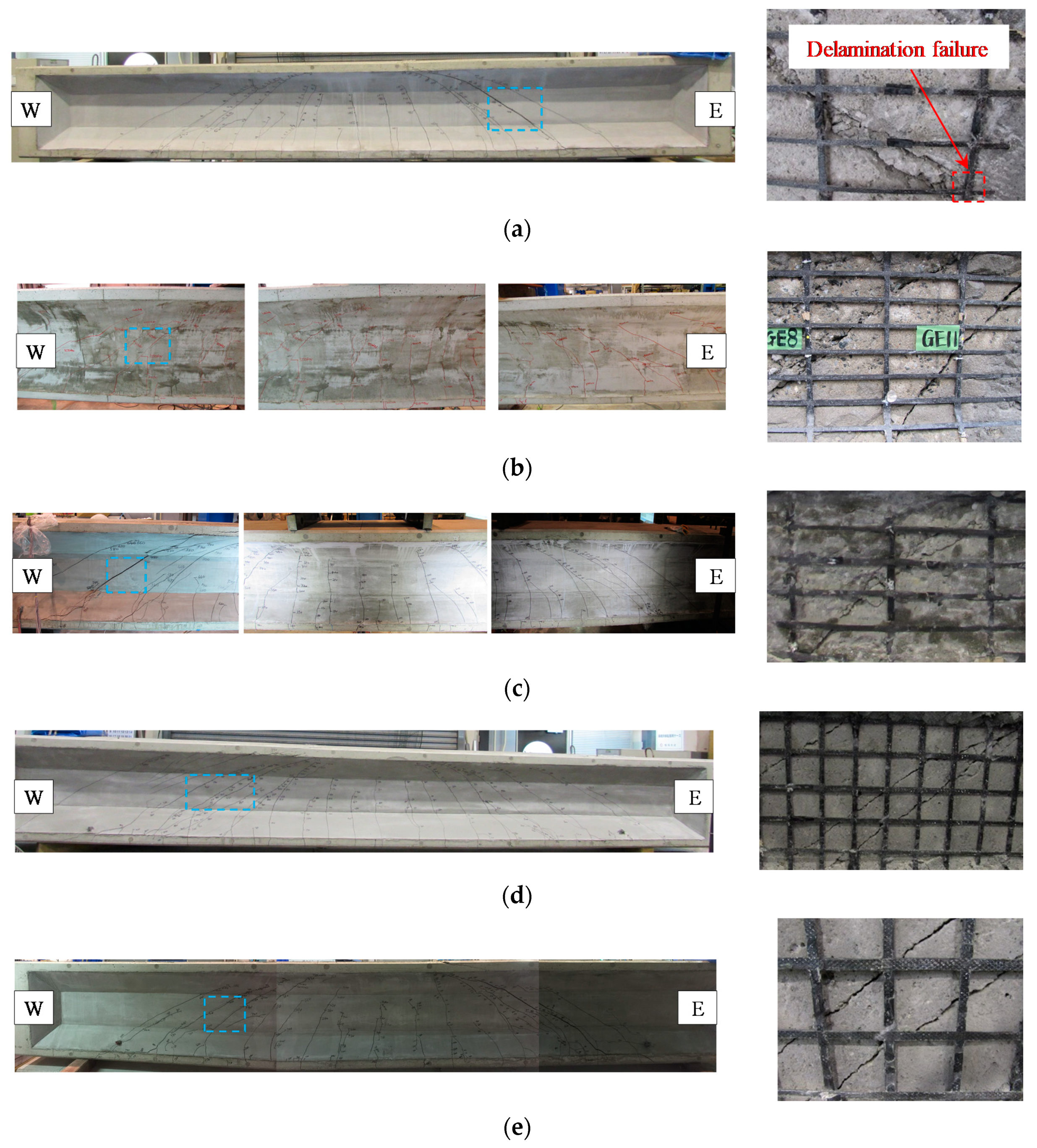
The strengthened beam specimens are subjected to shear force during the whole loading process, and it is worth noting that some scholars have proposed that the debonding failure of FRP composites generally occurred at the interface prior to concrete crushing [
49,
68,
69]. It can be observed from the experimental results that the local debonding failure occurred at the interface between the CFRP grid and the concrete in advance of the rupture of the CFRP grid. Therefore, the shear capacity evaluation method for concrete beams reinforced by a CFRP grid-PCM reinforcement layer, which is based on the effective strain of FRP rod introduced by JSCE’s Concrete Library [
70], needs to be utilized, and the expression of corresponding effective strain is represented as follows:
where
ρweb,
ρw are defined in Equations (1) and (2), respectively,
Es is defined as the elastic modulus of the tensile steel bars;
Eg is defined as the elastic modulus of FRP rods and thus vertical FRP grids are used instead;
and
are defined as the design compressive strength of concrete considering the size effect from the specimens and the average value of the axial compressive strength, respectively. The values of
and
are determined as:
where
Ped is defined as the effective tensile force of reinforcement in the axial direction;
is defined as the design bending moment and axis compressive force;
A and
h are defined as the total cross-sectional area and the height of the specimen, respectively.
Using the effective strain defined in Equation (10), it is possible to evaluate the shear value
V according to Equation (3). Comparing the calculated shear (
Vcal,rod) with the experimental ultimate shear capacity (
Pexp), a safety ratio is defined. In
Table 9, the values of
Vcal,rod,
Pexp and safety ratios are listed, corresponding to the experimental values of this study and some collected data from other results [
37,
51,
71]. The safety ratio values are in the range of 1.16 to 1.61 considering all strengthened beams. These values are much higher than 1.0, indicating that the method based on the effective strain of the FRP rod can be used to evaluate the shear capacity of RC beams using a CFRP grid and PCM layer. Similarly, the values of the effective strain can be evaluated from the experimental values of maximum strain of the CFRP grid (
εp,max) listed in
Table 9. The values increase with the reduction of the cross-sectional area of the CFRP grid. It can be seen that the smaller cross-sectional areas are, the better the deformation performance of the CFRP grid. If these strains are compared with the strains obtained by Equation (10) for the FRP rod (listed in
Table 9), the values are much higher. This is because the FRP grid can resist higher shear force by vertical grids, horizontal grids, and grid points (as the intersections of vertical and horizontal grids), meaning that both vertical and horizontal grids have an inherent relation rather than only a single vertical direction of FRP grids working like an FRP rod. For this reason, there is a great difference between their load-transferring mechanisms; this can explain why the previous calculation system can be used to predict the shear capacity, but always being over-predictive.
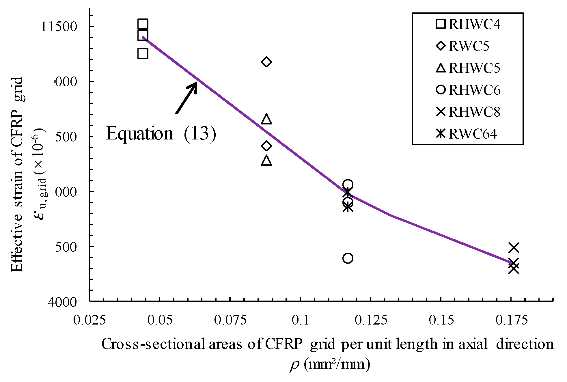
Therefore, a better evaluation method of shear capacity for concrete beams with CFRP grids should be developed to calculate or predict shear capacity more accurately than by using the previous method. To replace the effective strain corresponding to the FRP rod, the ultimate strain value of the FRP grid (
εu,grid) has been defined as the measured ultimate or debonding strain of the CFRP grid (also called effective strain of CFRP grid [
38,
40]) and has been explored through regression analysis, in two series of tests. The analysis is shown in
Figure 12 and the result is given as:
where
ρg is defined as the cross-sectional area of the CFRP grid per unit length in the horizontal direction.
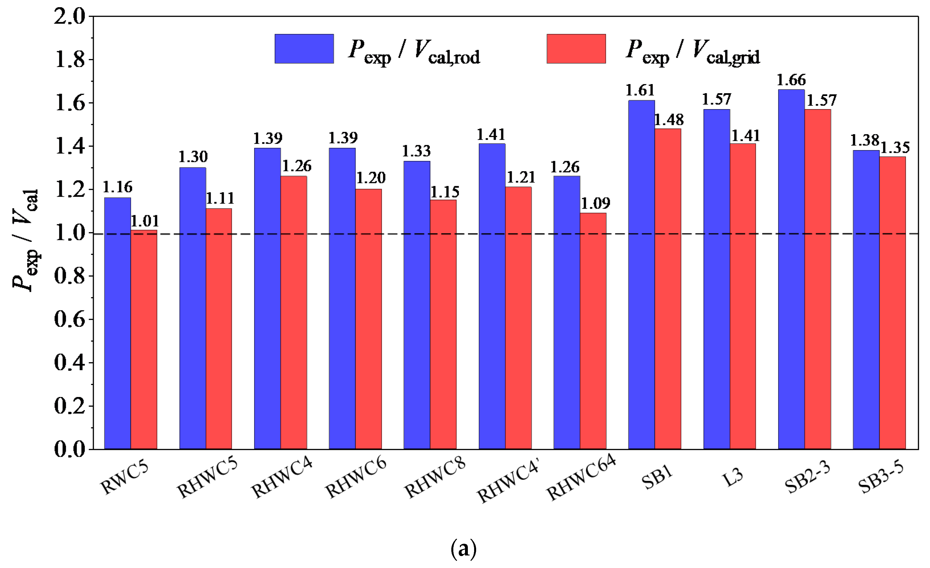
Considering the new definition for the strain, the values for shear can be re-evaluated (labelled as
Vcal,grid and shown in
Appendix A) and compared with those obtained previously (
Vcal,rod) in
Table 9. The comparison is plot as the chart of
Figure 13a. Again, the safety ratios of
Pexp to
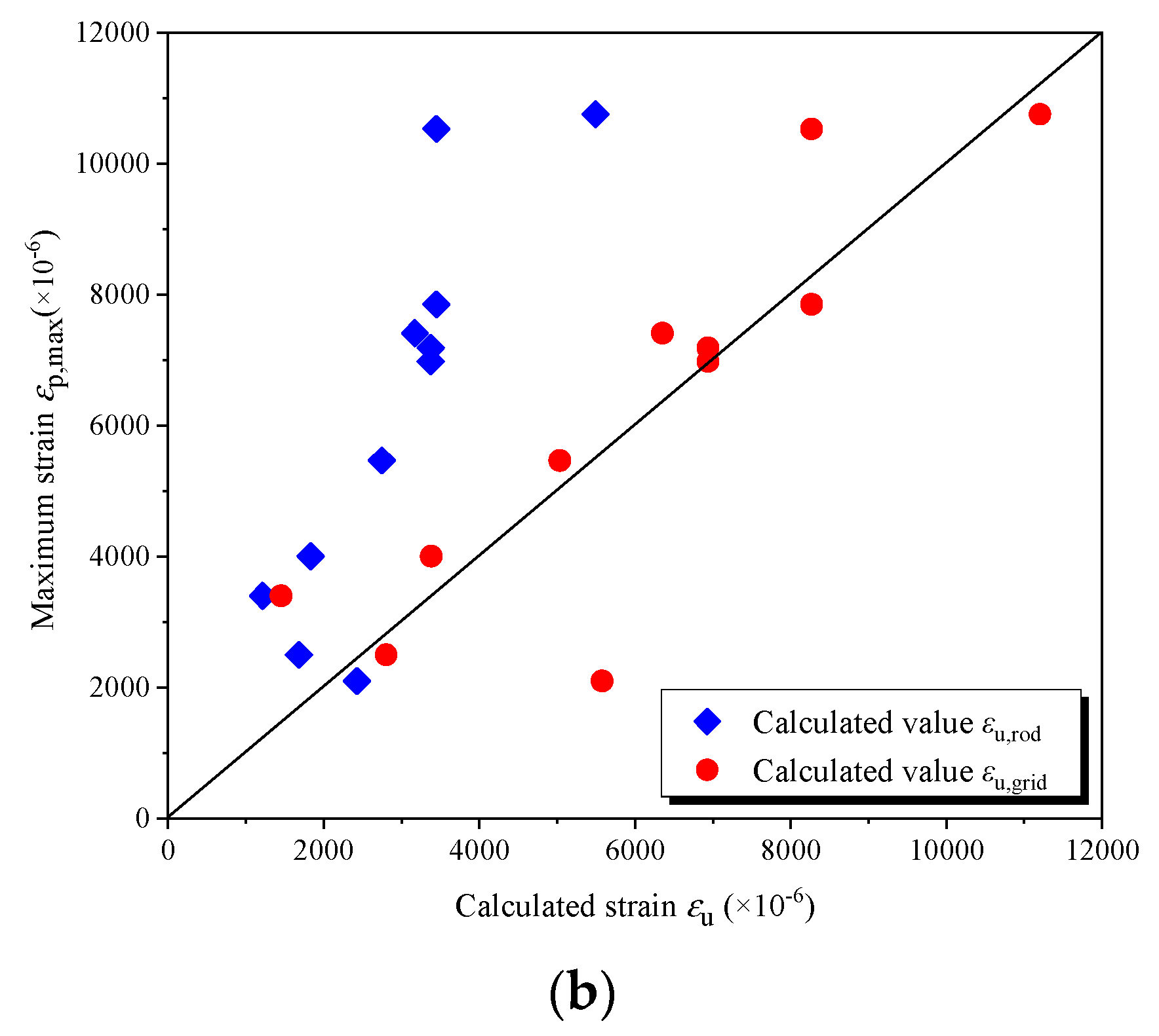
Vcal,grid are beyond 1.00 so they satisfy the safety requirement. Similarly, the strain value (
εu,grid) can be re-evaluated, and the values result much closer to the measured ones, as shown in
Figure 13b. It can be deduced that the latter calculated system, which is proposed to evaluate the shear capacity for concrete beams externally bonded with a CFRP grid-PCM reinforcement layer, is demonstrated to be a more reasonable approach than the previous method.


