Abstract
A cylindrical soft actuator is suitable for applications in which pneumatic or hydraulic cylinders are conventionally used. In this report, we discuss the force output model of a spring-reinforced-type cylindrical soft actuator. This type of actuator outputs a larger force than the air pressure multiplied by the pressure-receiving area. We construct a quasi-static model to explore the reason for this phenomenon, based on the strength of materials. A thick-walled cylinder model with three boundary conditions was defined and analyzed. The model indicates that the rubber cylinder itself transmits pneumatic pressure and contributes to the output force. We also modeled the relationship between the pressure and the elongation of the soft actuator. Experiments were conducted to evaluate the proposed models.
1. Introduction
Soft actuators, like McKibben pneumatic artificial rubber muscles [1,2], have a long history of development. They have a high power-to-weight ratio compared to electric motors and are key elements in lightweight robot arms by locating valves and compressors, apart from the link mechanism. Moreover, they are lighter than conventional metal cylinders and are flexible. The applications of these actuators include cooperating robots, for which safety is a critical concern due to their regular contact with human subjects [3,4], biomimetic robots [5,6], and even medical robots [7,8,9,10].
3D printers are currently being used to fabricate soft actuators. This facilitates the manufacturing of actuators with complex mechanisms, which has resulted in the development of a variety of soft robots [11]. The manufacturing process for soft actuators is simple and low cost. This involves the preparation of 3D-printed molds that are subsequently filled with liquid silicone rubber. PneuNet [12,13,14,15] is a major invention, which has an array of chambers on a fiber-reinforced base, which bends with the application of compressed air. It is applied to soft grippers [16] and durable multi-leg robots [17].
Linear soft actuators that are simple compared to PneuNets have also been developed. Their simple motion enables the easy design of soft robots since they can be used with conventional rigid-link mechanisms. They also have an advantage compared to metal pneumatic cylinders in that they do not have sliding parts. Working fluid such as air or water is sealed, preventing the leakage of fluid and the generation of dust. Furthermore, they enable high precision positioning [18] because no stick-slip occurs, in combination with an appropriate control system using precise sensors and servo valves.
Bellow actuators and reinforced cylindrical actuators are the representative examples of these actuators. Bellows, especially those made of rubber, are used for soft robotics [19]. However, rubber bellows expand radially and bursts when high pressure is applied, and fiber reinforcement is necessary.
Hawkes et al. proposed a simple cylindrical soft actuator [20]. In this case, a fiber is wound around the silicone rubber cylinder. The supply of compressed air into the cylinder causes elongation in the axial direction, while the fiber restricts radial expansion. The cylindrical soft actuator generates a linear motion, but this simple behavior leads to a wide array of potential robotic applications, as an alternative to conventional pneumatic hydraulic cylinders.
Moreover, pneumatic actuators can control the output force and estimate the external force using servo valves in conventional rigid link robots. Force control is useful for the manipulation of a variety of materials, especially for food and organs. Pneumatic cylinders are back-drivable and low-friction without reduction gears, and the product of the cross-section of the piston and the air pressure directly derives the external force. In this study, force estimation was implemented in a pneumatically-driven surgical robot [21]. In these highlighted examples, force estimation is realized only for rigid pneumatic robots. In this work, the authors extended the method to a soft robot and developed a system to estimate the grasping force of a surgical robot using a soft actuator [22].
A quasi-static model that describes the force output of a soft actuator is desirable for precise control and external force estimation.
Several works have reported on the analytical model of soft actuators, while most soft robots have complex dynamics and rely on numerical analysis. Polygerinos et al. modeled a bending soft actuator reinforced by fiber [23]. Bishop-Moser et al. analyzed the relationship between the deformation of a cylindrical actuator and the helical angle of the reinforcement fiber [24]. Conventional modeling of cable-driven bending manipulators has also been investigated [25,26,27,28]. However, linear cylindrical actuators have not been modeled because their characteristics are considered to be simple. The output force of the actuator was considered to be the pressure multiplied by the pressure-receiving area. However, we experimentally determined that the actual output force has a larger value than that obtained using this simple calculation.
In this report, we present a model that describes the relationship between the output force and the pressure of a cylindrical linear soft actuator. In contrast to the previous works that neglected the thickness of the rubber cylinder, this report analyses the effect of the stress of the rubber cylinder by using fundamental equations for the strength of materials. We used the thick-walled cylinder model, considering the Poisson ratio of the material. It is revealed that the rubber material itself transmits the pressure and causes the axial output force. We also analyzed the pressure-elongation model, which is generally non-linear, given that the model is also essential for force estimation. A soft actuator reinforced by a metal coil was fabricated, and experiments to confirm these models were conducted using a prototype.
Section 2 explains the structure of the cylindrical soft actuator used in this investigation. Next, the relationship between the pressure and the output force of the actuator is derived, using the thick-walled cylinder model, in Section 3. Then, the relationship between the pressure and the displacement of the actuator is presented in Section 4. In Section 5, the results of experiments to validate the model are shown. Section 6 gives the conclusions.
2. Structure of a Cylindrical Soft Actuator
Figure 1 shows the structure of a cylindrical soft actuator, and the prototype is shown in Figure 2. It is a rubber cylinder covered by a reinforcement material. It elongates along the axial direction when working fluid is supplied inside the chamber, while the reinforcement material prevents radial expansion.
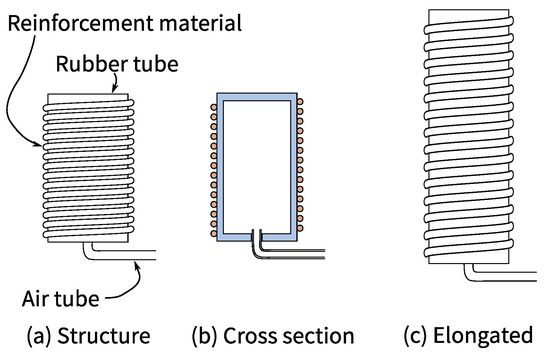
Figure 1.
Structure of a coil-reinforced soft actuator.
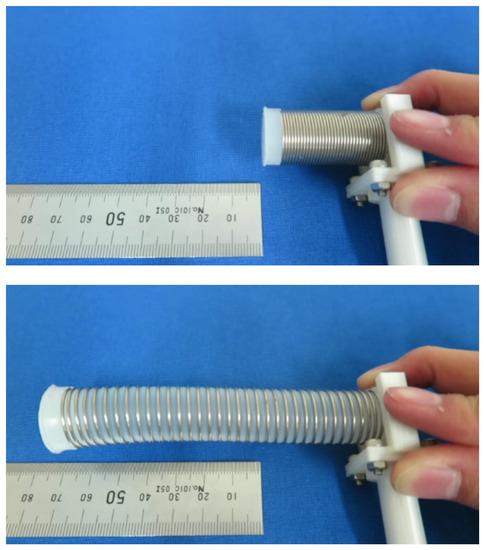
Figure 2.
Prototype of a soft actuator.
The reinforcement material can be a fiber or a spring. A fiber-reinforced actuator has a fiber wound around the rubber cylinder, which is flexible and lightweight and suitable for human–machine interaction, such as in the case of a cooperation robot. A spring-reinforced actuator, however, operates with a higher pressure than the fiber-reinforced actuator.
Both a cylindrical soft actuator and a McKibben-type artificial muscle generate linear motion. The difference is that the artificial muscle contracts about 20% of its natural length and outputs strong force, while the cylindrical soft actuator expands about 300% of its natural length. The output force is no larger than that of a conventional pneumatic cylinder.
3. Relationship between Pressure and Output Force
Consider an infinitely-long thick-walled cylinder with an inner diameter and the outer diameter , as shown in Figure 3. The following conditions are given, from the structure of the soft actuator.
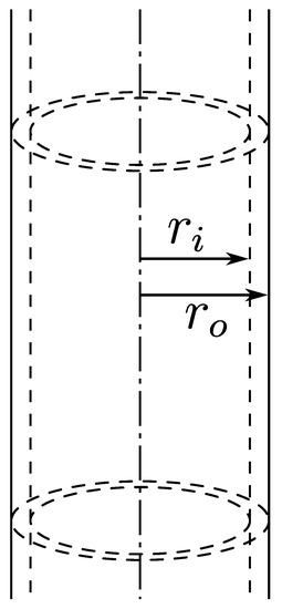
Figure 3.
Infinitely-long cylinder model.
- Condition 1.
- The pressure P is applied uniformly to the inner wall of the cylinder.
- Condition 2.
- Radial and circumferential deformation are zero because the outer wall of the cylinder is restrained by a fiber or a spring.
- Condition 3.
- Elongation of the cylinder, or axial strain, is also zero for simplicity. The following equations are also valid when the cylinder is elongated, by considering the deviation from a reference point (arbitrary length without external forces).
In a small volume of the thick-walled cylinder shown in Figure 4, the force equilibrium in polar coordinates along r-axis is written as follows:
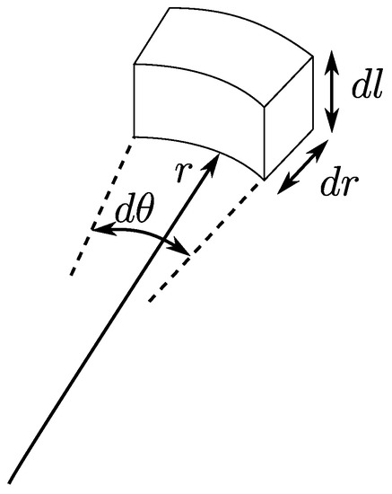
Figure 4.
Small volume of a cylinder.
The first term is the force from the outer face, and the second is from the inner face, which represents the product of pressure and area. The last term represents the force from the sides, given that the side faces have angles, and the force perpendicular to these faces results in the radial force: from each side. By ignoring high-order terms () and approximating as , this equation can be rearranged as follows:
The basic equations of stress and strain are:
where , , E, and are the strain, the stress, Young’s modulus, and Poisson’s ratio, respectively. The subscript i denotes the axis index.
Condition 3 is represented as . Substituting it into Equation (5) yields:
The following differential equation is obtained by substituting it into Equation (2):
This can be rewritten as:
and then, we get:
where and are the constants of integration.
Next, we consider the circumferential strain . The circumferential length of the material changes by when the radial displacement is . Thus,
From Condition 2, that the outer wall is radially constrained, when . The preceding equation becomes:
Thus, the constant is derived as follows:
Then, we use Condition 1 that at and obtain the following:
It should be noted that the signs for stress and air pressure are different, because stress is defined to be positive for tension, but air pressure is positive for compression. In this case, we introduce a new variable defined as:
and (21) becomes the following simple expressions.
The variable denotes the pressure transmission ratio. When , the rubber material fully transmits the pressure to the axial direction in the same manner as the fluid. A dimensionless expression of the preceding equation is given as follows by letting :
Figure 5 shows the relationship between and for different Poisson’s ratio, where a larger indicates a thinner rubber wall. A small change of affects strongly when is near 0.5. Poisson’s ratio should be identified experimentally, because this value deviates significantly for rubber materials in general.
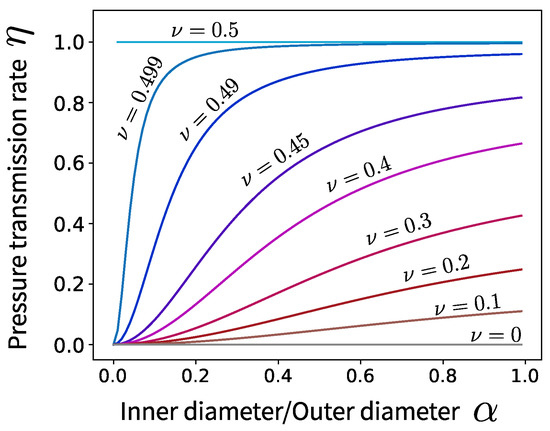
Figure 5.
Relationship between and .
Finally, the relationship between the pressure P and the actuator output force F is written as follows:
where is the cross-sectional area of the chamber and is the cross-sectional area of the rubber cylinder.
4. Relationship between Force and Displacement
This section presents a model that describes the relationship between the force applied to an actuator and displacement, which is also necessary for force control. The relationship is written as follows:
where x, , F, , and denote the displacement of the actuator, the output force, the driving force by the working fluid, the spring coefficient of the reinforcement coil, and the elastic force of the rubber material, respectively. is usually a nonlinear function since the strain of the rubber cylinder is large.
We use a simple nonlinear elastic model as described in the following. Firstly, it is assumed that the Poisson’s ratio of the rubber is 0.5, which implies that the volume of the rubber cylinder is constant. Under this assumption, elongation of the actuator results in the reduction of the cross-sectional area. We calculated the instantaneous cross-sectional area and the corresponding spring coefficient at the specific length, then calculated its integral to obtain the elastic force.
From the constant volume assumption, we obtain:
where , , and are the outer diameter, inner diameter, and the inner diameter at the initial state, of the rubber cylinder, respectively. The left-hand side and the right-hand side are the volume after deformation and that before deformation, respectively. The force-displacement relationship is instantaneously linear, and it is written as:
where is the instantaneous spring constant. This is just a differential form of Hooke’s law. The constant can be written as follows:
Here, l, are the length and the natural length of the actuator, respectively, and .
Calculating the integrals yields:
Given that the boundary condition is that at , the constant is . Finally, we get:
Figure 6 shows the relationship between x and . The preceding equations assume a linear stress-strain relationship. For large deformation of rubber materials, a nonlinear model based on polymer molecule chains [29] is useful.
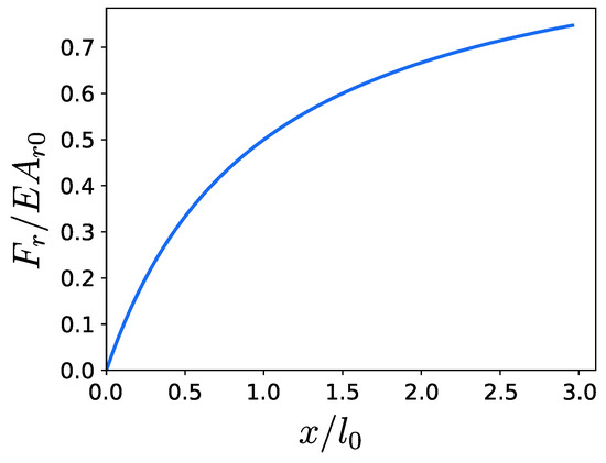
Figure 6.
Relationship between x and .
5. Experiments
5.1. Experimental Setup
We measured the pressure-output relationship and the force-displacement relationship to verify the proposed models.
The prototype actuator had a SUS304WPB stainless steel coil spring (L066, Accurate Inc., Saitama, Japan), which had an outer diameter of 20 mm and a wire diameter of 1 mm. We prepared three different rubber cylinders with inner diameters of 16 mm, 14 mm, and 10 mm. Their length was 35 mm.
The outer diameter of the rubber was 19 mm, the same as the mean diameter of the spring. We poured the liquid silicone into the mold containing the spring, and the silicone assumed the inner shape of the spring. Silicone rubber with a hardness of 30 A was used as the rubber material (Dragon Skin 30, Smooth-On, Macungie, PA, USA). An air tube with ø2 mm was attached on the bottom of the actuator.
Figure 7 shows the fabrication process for the soft actuator. Firstly, we assembled the molds and inserted the spring. Next, the polymerization-type silicone was poured into the mold. The silicone was cured for 16 h at 23 . Next, new silicone was poured into a mold to form the bottom part, and the cylindrical component was placed on top. Finally, the bottom part was cured, and the base plate and a pneumatic tube were assembled.
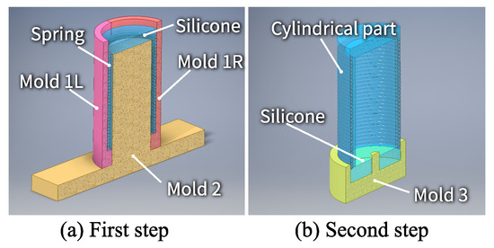
Figure 7.
Fabrication process of the soft actuator.
The rubber cylinder had a groove that was attributable to the shape of the spring. The groove played the role of preventing the spring from slipping.
We implemented a PI control of the pressure as shown in Figure 8. The input of the controller was taken as the error between the measurement of a pressure sensor (PSE540, SMC, Tokyo, Japan) and a reference pressure. The output of the controller was the voltage to a servo valve (MPYE, FESTO, Esslingen, Germany). Table 1 shows the control gains. A PC (Ubuntu 14.04 and RTAI) controlled the system with a sampling time of 1 ms.
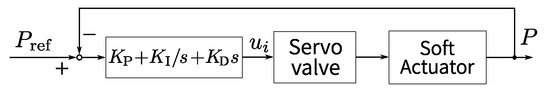
Figure 8.
Block diagram of pressure control.

Table 1.
Control parameters.
5.2. Pressure and Output Force
We used a six-axis force torque sensor (BL-NANO sensor, BL Autotec, Kobe, Japan) in front of the soft actuator, as shown in Figure 9, and measured the output force. The force sensor output an analog voltage, and its maximum load was 24.5 N.
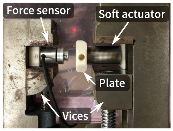
Figure 9.
Experiment apparatus.
We measured the output force six times by changing the distance between the actuator and the force sensor each time.
Figure 10 shows the experimental result. The slope of the line represents the equivalent cross-sectional area, written as in Equation (25). Table 2 shows the measurement results of the equivalent cross-sectional area. The pressure transmission ratio was 1.07, since , . It was confirmed that the pressure transmission ratio was smaller when the inner diameter of the silicone rubber was smaller, as shown in Table 3.
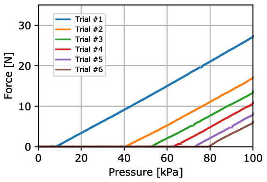
Figure 10.
Experimental result, ø16 mm.
Table 2.
Cross-sectional area, ø16 mm.
Table 3.
Experimental results for various inner diameters.
A small error of the outer and inner diameter caused a large error of , resulting in a value greater than one, especially when the rubber wall was thin. For example, a 0.1-mm error of the diameter led to a 0.03 change for . Other causes of the error may be the force sensor and the pressure sensor.
5.3. Force and Displacement
A linear encoder (MLS-12, Microtech Laboratory Inc., Sagamihara, Japan) was attached to the soft actuator to measure the displacement caused by the force. The resolution of the encoder was 0.04 mm.
Figure 11 shows the result. The solid line and the dashed line represent the measurement value and theoretical value, respectively. When plotting the theoretical value, we set and E in Equations (26) and (33) as and , respectively, according to the datasheet provided by the manufacturer. The natural length of the actuator was 35 mm. The theoretical value fit the experimental value well for low pressure. However, the experimental values differed from theory for high pressure.
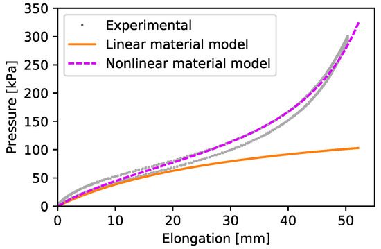
Figure 11.
Relationship between elongation and pressure.
The magenta dashed line in Figure 11 shows the results obtained using the proposed method, combined with the nonlinear stress-strain relationship given by Arruda et al. [29]. The model is expressed as follows:
where and are the constants depending on the material used and . The model gave a better description of the nonlinear behavior of the actuator.
5.4. Discussion
In terms of the pressure-output relationship, it was confirmed that a smaller inner diameter of the actuator resulted in a smaller pressure transmission ratio, as derived in Section 3. Theoretically, the pressure transmission ratio was smaller than one; however, the experimental results revealed that the value was larger than one, due to the error associated with the diameter. The error can be reduced by precise manufacturing of the actuator. However, this problem is secondary given that the purpose of this experiment was not to calculate accurate , but to investigate the characteristics of according to the inner diameter to evaluate the efficacy of the model. We did not consider the dynamics in this investigation because the quasi-static characteristics of the soft actuator were unique compared with conventional actuators. The dynamics of the soft actuator can be approximated by a simple mass-damper model.
For the force-displacement relationship, the model worked well under low pressure, as shown in Figure 11. The proposed method also worked under high pressure when combined with an existing nonlinear stress-strain model of rubber materials. Actual rubber materials exhibit nonlinear characteristics and become harder under large strain. The proposed model can be improved by considering the nonlinearity of materials. In addition, the experimental results resulted in a simple curve, which is possible for polynomial approximation in practice.
The hysteresis seen in Figure 11 was caused by the silicone material. It was smaller than the general profile of rubber material, because the stiffness of the metal spring with small hysteresis was dominant for the characteristics of the proposed actuator. This result implies that a precise soft actuator is possible by making the rubber cylinder thinner or using materials with lower hardness.
6. Conclusions
In this investigation, a quasi-static model of a soft actuator with reinforcement material on the outer wall of the rubber cylinder was constructed. It was theoretically demonstrated that the output force of the soft actuator was larger than the pure product of the inner cross-sectional area and the pressure since the rubber wall also transmitted pressure using a thick-walled cylinder model.
We also modeled the nonlinear relationship of the displacement of the actuator and the driving force. The model revealed that the stiffness was reduced by the elongation of the actuator. This was valid in the low-pressure range as shown experimentally. Compensation using Arruda’s model increased the accuracy in high-pressure range.
It was possible to estimate precisely the external force applied to the soft actuator using the proposed model. Potential applications of force control and force estimation include robots for the food industry, surgical robots, and home robots, which require force control for safe interaction with humans or delicate objects.
Author Contributions
Conceptualization, T.K. (Takahiro Kanno), O.A., and K.K.; methodology, T.K. (Takahiro Kanno) and T.K. (Toshihiro Kawase); software, S.O. and O.A.; investigation, S.O. and O.A.; writing, original draft preparation, T.K. (Takahiro Kanno); writing, review and editing, T.K. (Toshihiro Kawase) and T.M.; supervision, T.M.; project administration, K.K.
Funding
This work was supported by JSPS KAKENHI Grant Number 18K13725 and the Research Center for Biomedical Engineering.
Conflicts of Interest
The authors declare no conflict of interest.
References
- Chou, C.P.; Hannaford, B. Measurement and modeling of McKibben pneumatic artificial muscles. IEEE Trans. Robot. Autom. 1996, 12, 90–102. [Google Scholar] [CrossRef]
- Noritsugu, T. Pneumatic Soft Actuator for Human Assist Technology. In Proceedings of the 6th JFPS International Symposium on Fluid Power, Tsukuba, Japan, 7–10 November 2005; pp. 11–20. [Google Scholar]
- Kim, J.; Alspach, A.; Yamane, K. 3D printed soft skin for safe human-robot interaction. In Proceedings of the 2015 IEEE/RSJ International Conference on Intelligent Robots and Systems (IROS), Hamburg, Germany, 28 September–2 October 2015; pp. 2419–2425. [Google Scholar] [CrossRef]
- Polygerinos, P.; Correll, N.; Morin, S.A.; Mosadegh, B.; Onal, C.D.; Petersen, K.; Cianchetti, M.; Tolley, M.T.; Shepherd, R.F. Soft Robotics: Review of Fluid-Driven Intrinsically Soft Devices; Manufacturing, Sensing, Control, and Applications in Human-Robot Interaction. Adv. Eng. Mater. 2017, 19, 1700016. [Google Scholar] [CrossRef]
- Trivedi, D.; Rahn, C.D.; Kier, W.M.; Walker, I.D. Soft robotics: Biological inspiration, state of the art, and future research. Appl. Bionics Biomech. 2008, 5, 99–117. [Google Scholar] [CrossRef]
- Suzumori, K.; Endo, S.; Kanda, T.; Kato, N.; Suzuki, H. A Bending Pneumatic Rubber Actuator Realizing Soft-bodied Manta Swimming Robot. In Proceedings of the 2007 IEEE International Conference on Robotics and Automation, Roma, Italy, 10–14 April 2007; pp. 4975–4980. [Google Scholar] [CrossRef]
- Cianchetti, M.; Ranzani, T.; Gerboni, G.; Nanayakkara, T.; Althoefer, K.; Dasgupta, P.; Menciassi, A. Soft Robotics Technologies to Address Shortcomings in Today’s Minimally Invasive Surgery: The STIFF-FLOP Approach. Soft Robot. 2014, 1, 122–131. [Google Scholar] [CrossRef]
- Polygerinos, P.; Lyne, S.; Wang, Z.; Nicolini, L.F.; Mosadegh, B.; Whitesides, G.M.; Walsh, C.J. Towards a soft pneumatic glove for hand rehabilitation. In Proceedings of the 2013 IEEE/RSJ International Conference on Intelligent Robots and Systems, Tokyo, Japan, 3–7 Novemver 2013; pp. 1512–1517. [Google Scholar] [CrossRef]
- Polygerinos, P.; Wang, Z.; Galloway, K.C.; Wood, R.J.; Walsh, C.J. Soft robotic glove for combined assistance and at-home rehabilitation. Robot. Auton. Syst. 2015, 73, 135–143. [Google Scholar] [CrossRef]
- Ranzani, T.; Gerboni, G.; Cianchetti, M.; Menciassi, A. A bioinspired soft manipulator for minimally invasive surgery. Bioinspir. Biomim. 2015, 10, 035008. [Google Scholar] [CrossRef]
- Rus, D.; Tolley, M.T. Design, fabrication and control of soft robots. Nature 2015, 521, 467–475. [Google Scholar] [CrossRef]
- de Payrebrune, K.M.; O’Reilly, O.M. On constitutive relations for a rod-based model of a pneu-net bending actuator. Extrem. Mech. Lett. 2016, 8, 38–46. [Google Scholar] [CrossRef]
- Holland, D.P.; Park, E.J.; Polygerinos, P.; Bennett, G.J.; Walsh, C.J. The Soft Robotics Toolkit: Shared Resources for Research and Design. Soft Robot. 2014, 1, 224–230. [Google Scholar] [CrossRef]
- Ilievski, F.; Mazzeo, A.D.; Shepherd, R.F.; Chen, X.; Whitesides, G.M. Soft Robotics for Chemists. Angew. Chem. 2011, 123, 1930–1935. [Google Scholar] [CrossRef]
- Marchese, A.D.; Katzschmann, R.K.; Rus, D. A Recipe for Soft Fluidic Elastomer Robots. Soft Robot. 2015, 2, 7–25. [Google Scholar] [CrossRef]
- Hao, Y.; Gong, Z.; Xie, Z.; Guan, S.; Yang, X.; Ren, Z.; Wang, T.; Wen, L. Universal soft pneumatic robotic gripper with variable effective length. In Proceedings of the 2016 35th Chinese Control Conference (CCC), Chengdu, China, 27–29 July 2016; pp. 6109–6114. [Google Scholar] [CrossRef]
- Tolley, M.T.; Shepherd, R.F.; Mosadegh, B.; Galloway, K.C.; Wehner, M.; Karpelson, M.; Wood, R.J.; Whitesides, G.M. A Resilient, Untethered Soft Robot. Soft Robot. 2014, 1, 213–223. [Google Scholar] [CrossRef]
- Kawashima, K.; Arai, T.; Tadano, K.; Fujita, T.; Kagawa, T. Development of coarse/fine dual stage using pneumatically driven bellows actuator and cylinder with air bearings. Precis. Eng. 2010, 34, 526–533. [Google Scholar] [CrossRef]
- Martinez, R.V.; Fish, C.R.; Chen, X.; Whitesides, G.M. Elastomeric Origami: Programmable Paper-Elastomer Composites as Pneumatic Actuators. Adv. Funct. Mater. 2012, 22, 1376–1384. [Google Scholar] [CrossRef]
- Hawkes, E.W.; Christensen, D.L.; Okamura, A.M. Design and implementation of a 300% strain soft artificial muscle. In Proceedings of the 2016 IEEE International Conference on Robotics and Automation (ICRA), Stockholm, Sweden, 16–21 May 2016; pp. 4022–4029. [Google Scholar] [CrossRef]
- Tadano, K.; Kawashima, K.; Kojima, K.; Tanaka, N. Development of a Pneumatic Surgical Manipulator IBIS IV. J. Robot. Mechatron. 2010, 22, 179–188. [Google Scholar] [CrossRef]
- Takizawa, T.; Kanno, T.; Miyazaki, R.; Tadano, K.; Kawashima, K. Grasping force estimation in robotic forceps using a soft pneumatic actuator with a built-in sensor. Sens. Actuators A Phys. 2018, 271, 124–130. [Google Scholar] [CrossRef]
- Polygerinos, P.; Wang, Z.; Overvelde, J.T.B.; Galloway, K.C.; Wood, R.J.; Bertoldi, K.; Walsh, C.J. Modeling of Soft Fiber-Reinforced Bending Actuators. IEEE Trans. Robot. 2015, 31, 778–789. [Google Scholar] [CrossRef]
- Bishop-Moser, J.; Kota, S. Design and Modeling of Generalized Fiber-Reinforced Pneumatic Soft Actuators. IEEE Trans. Robot. 2015, 31, 536–545. [Google Scholar] [CrossRef]
- Webster, R.J.; Jones, B.A. Design and kinematic modeling of constant curvature continuum robots: A review. Int. J. Robot. Res. 2010, 29, 1661–1683. [Google Scholar] [CrossRef]
- Wang, H.; Wang, C.; Chen, W.; Liang, X.; Liu, Y. Three-Dimensional Dynamics for Cable-Driven Soft Manipulator. IEEE/ASME Trans. Mechatron. 2017, 22, 18–28. [Google Scholar] [CrossRef]
- Renda, F.; Giorelli, M.; Calisti, M.; Cianchetti, M.; Laschi, C. Dynamic model of a multibending soft robot arm driven by cables. IEEE Trans. Robot. 2014, 30, 1109–1122. [Google Scholar] [CrossRef]
- Tatlicioglu, E.; Walker, I.D.; Dawson, D.M. New dynamic models for planar extensible continuum robot manipulators. In Proceedings of the IEEE International Conference on Intelligent Robots and Systems, San Diego, CA, USA, 29 October–2 November 2007; pp. 1485–1490. [Google Scholar] [CrossRef]
- Arruda, E.M.; Boyce, M.C. A three-dimensional constitutive model for the large stretch behavior of rubber elastic materials. J. Mech. Phys. Solids 1993, 41, 389–412. [Google Scholar] [CrossRef]


© 2019 by the authors. Licensee MDPI, Basel, Switzerland. This article is an open access article distributed under the terms and conditions of the Creative Commons Attribution (CC BY) license (http://creativecommons.org/licenses/by/4.0/).