Article

Non-Contact Measurement of Small-Module Gears Using Optical Coherence Tomography

1
Laboratory of Optics, Terahertz and Non-Destructive Testing, School of Mechanical Engineering and Automation, Fuzhou University, Fuzhou 350108, China
2
School of Mechanical and Electrical Engineering, Putian University, Putian 351100, China
3
School of Mechatronic Engineering and Automation, Shanghai University, Shanghai 200072, China
*
Author to whom correspondence should be addressed.
Appl. Sci. 2018, 8(12), 2490; https://doi.org/10.3390/app8122490
Submission received: 19 September 2018 / Revised: 21 November 2018 / Accepted: 22 November 2018 / Published: 4 December 2018
(This article belongs to the Special Issue Optical Coherence Tomography and its Applications)

Abstract

:
Due to the small size and harsh transmission conditions of small-module gears, it is very difficult to measure gear characteristics with a modulus smaller than 1 mm. We proposed an optical coherence tomography (OCT) method for measuring small-module gears. Testing of a 30-tooth copper gear with a small modulus of 0.5 mm was carried out for the measurement of its modulus, tooth parameter, tooth number, pressure angle, modification coefficient, and tooth thickness by using OCT. In addition, the influencing factors on the measurement were discussed. The whole teeth profile of a 0.2 mm modulus gear was imaged by processing of the data collected from different clamping angles. Compared with the visual imaging without depth information and small-scale microscopic imaging, the OCT method has shown its superiority, and it has potential in the application of the measurement of micro gears with a small modulus of less than 0.2 mm.

1. Introduction

Micro gears with a modulus of 0.05 mm to 0.5 mm are widely used in precision measuring tools, navigation instruments, and chronometer clocks [1]. In addition, it also widely used as a key precision driving part in defense industry and the manufacturing of micro machinery [2]. In the process of transmission, if the tooth surface is damaged, it will affect the normal operation of machine maintenance and mechanical transmission. Because the quality of the tooth surface of the micro gears affects the precision, noise, and life of the instrument, the precision and quality of the measurement of small gears has higher requirements than that of the normal one.
If traditional contact measurement technology and instruments are used to measure small gears, even a thin and small measurement head is difficult to insert into the teeth, resulting in the difficulty in carrying out measurements; also, the contact measurement head sometimes damage the teeth. In addition, the rigidity of the measuring rod is poor, it is difficult to determine the deformation error caused by the measuring rod, the error is difficult to read, the measurement accuracy and repeatability are difficult to guarantee, and sometimes it is impossible to do the measurement at all. Because of the small modulus, it is difficult to obtain the tooth profile with the naked eye. It needs to be aligned under the microscope, which is inconvenient for the measurement [3]. Therefore, high-automation requirements of the measuring instrument are required. Some studies introduced the contact gear measuring instrument developed recently, it is found that the minimum gear modulus can be measured as 0.2 mm, and the diameter of the measuring rod is 0.25 mm [2]. In 2003, the researcher from Ogashihara company has found that it was difficult to measure the gears with modules that are less than 0.3 mm using contact instruments [4]. Therefore, the existing contact measurement techniques and instruments are still unable to meet the requirements of the precision micro gear, especially the precision measurement of micro gears that are produced by mass production [2].
Contact CNC (Computer Numerical Control) micro-gear measurement based on the coordinate method [5] is one of the current methods of detections for small-module gears. This method has high precision, high measurement efficiency, and a wide application range [6], but the tooth profile detected by this contact measurement cannot be too small, and therefore, it cannot meet the requirements of micro gear measurement. Non-contact measurement technology based on CCD (Charge Coupled Device) measurement [7,8] is the second common technique that has the advantages of non-contact, fast speed, and strong anti-interference ability in the field. However, it also has the problem that only the tooth profile of the end face of the gear can be detected, and it is difficult to detect the tooth profile in the direction of tooth width. Contact measurement technology based on an optical fiber probe [9,10] and gear meshing measurement technology is employed. Although the fiber optic probe has begun to be applied to measure the small-module gear, the main problem of the optical fiber probe is its measuring efficiency and its value transfer [3].
Optical coherence tomography (OCT) is a technique to measure and process the interference intensity of scattered light in the measured sample with the reference light by using the light interference principle. Subsequently, a high-resolution depth image is reformed to express the internal microstructure of the sample [11]. The technique has the ability of biopsy, with a resolution up to micrometers, and it can obtain non-invasive two-dimensional and three-dimensional images [12], and now it has been used in in industrial fields for the measurement of tablet coatings [12], fiber composites, MEMS (Micro Electro Mechanical Systems) devices [13], thin sheets and artworks, etc. In the present work, we applied OCT to the measurement of the micro-gear with a modulus of 0.5 mm, and the detection of the tooth profile of interest was carried out. The module, tooth number, pressure angle, modification coefficient, and other basic parameters of the gear were obtained in the work. In addition, by controlling the rotation degree of the sample platform, optical measurements can be carried out on different parts of the tooth profile. For example, parameters such as tooth thickness and pitch can be obtained by measuring the profile of the tooth side; also, the reconstruction of the entire tooth profile with a smaller modulus gear such as 0.2 mm can be realized by using data imaging algorithms.
The optical coherence tomography method is used to measure the small-module gear, which can avoid the contact measurement problem caused by the small size of the measured part [14], and can increase the measurement precision. Furthermore, it can also solve the difficulty that visual measurement and microscopic measurement are unable to obtain the contour of any position in the depth direction of the tooth width.

2. Methods and Experiments

A spectral domain OCT system (GAN 210C1, Thorlabs, Newton, New Jersey, United States) was used for the measurement of a small-module copper gears. The center wavelength of the light source was 930 nm. The horizontal resolution in air was 6.0 um. The sensitivity was 93 dB for a 36 kHz scanning speed, and 101 dB under a 5.5 kHz scanning speed [15]. The schematic diagram of the system was shown in Figure 1. The scanning range in the experiment was 6 mm × 3 mm, including 1024 × 1024 sample points. The size of each sample point was 5.86 um × 2.85 um.

2.1. Measurement of the Geometric Parameters of the Gears

As the light transmits from the tooth tip to the tooth root during the tooth profile measurement, the reflected light received will be the best if the detector is at the vertical incident position. Therefore, when the gear tooth is vertically placed, the reflected light of the tooth tip and tooth root is the strongest. When we were interested in the profile of the tooth side, we could get a clear profile of the tooth side by rotating the gear at a certain angle, making the tooth side perpendicular to the incident light. Different tooth profiles with different angles of incident light were measured, as shown in Figure 2. It demonstrated that the smaller the angle between tooth surface and incident light, the better the OCT profile of the tooth. Therefore a best configuration as in Figure 2b was chosen for measurement and analysis, as follows.

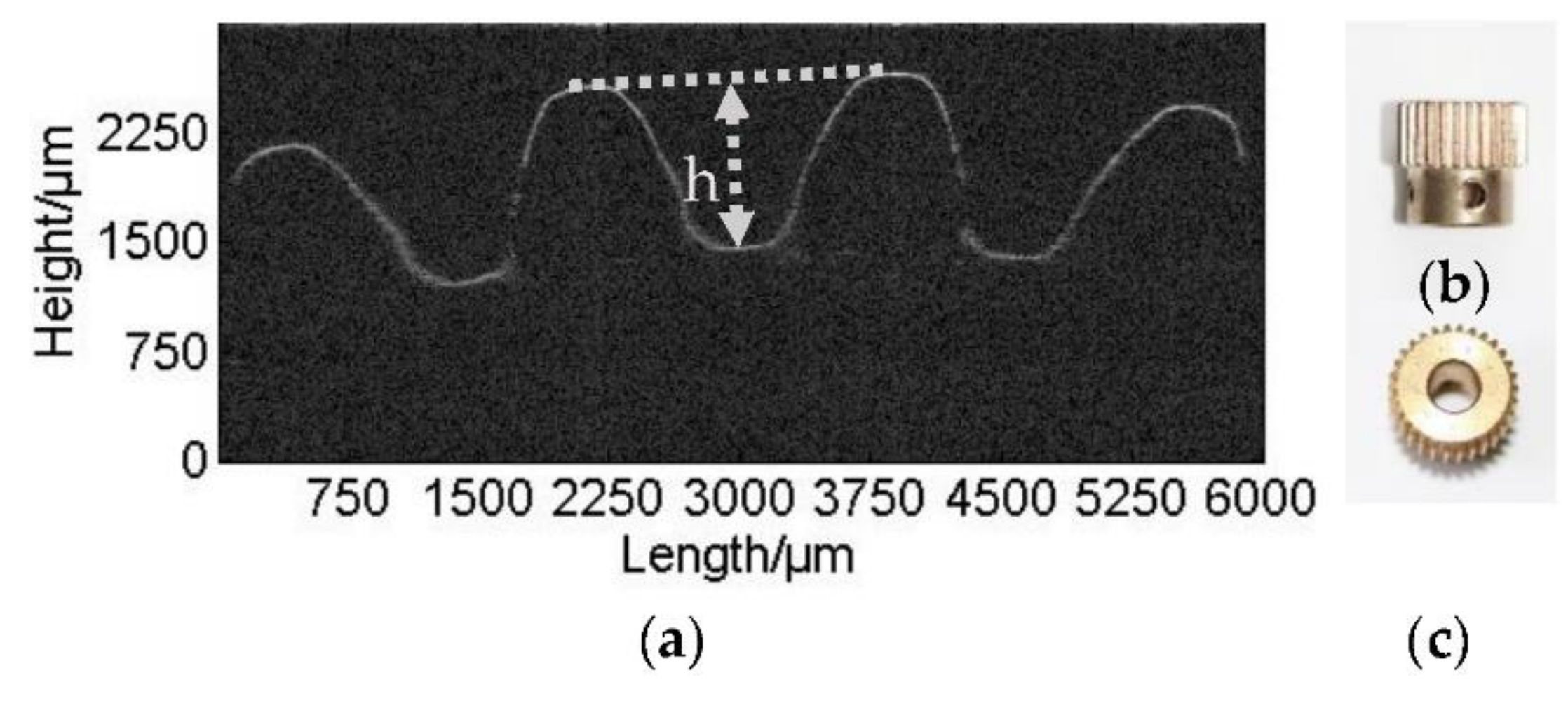
2.1.1. Analysis of Module, Addendum Coefficient, and Top Clearance Coefficient

The gear module is defined as a basic parameter of gears. The parameters of the gear reference circle diameter, tooth tip circle diameter, tooth root circle diameter, tooth thickness, and tooth width are closely related to the module [16], and they determine the size of the tooth. Therefore, it is very important to map out the gear modulus first when measuring the gear parameters.
Figure 3a showed an OCT image of a small-module metal copper gear. The figure contained four teeth in the scanning range. Figure 3b,c are the right view and top view of the copper gear measured.
The OCT image was firstly binarized by using the “im2bw” function in MatLab R2014a (MathWorks, United States). Second, the “imfill” function was employed to fill the image and to remove internal holes. Finally, the contour of the gear was extracted using the “bwperim” function. The edge position of the tooth tip and the tooth root of the gear could be obtained by the slope of the tooth profile, which was shown in Figure 3. The tooth tip was located at the position where the slope of a tooth profile changed from positive to negative, whilst the tooth root was at the position where the slope changed from negative to positive. The depth of the gear h could be calculated once the tooth tip and root were achieved. In addition, in order to reduce the errors of the location of the tip and root of the tooth, we measured three tooth profiles, and we calculated the average depth of the gear of three teeth to determine a more accurate tooth height. Subsequently, the modulus m could be obtained as:
m = h / ( 2 h a * + c * )
where h a * is the addendum coefficient and c * is the top clearance coefficient. These two normative tooth parameters had been used in Equation (1) ( h a * = 1.0, c * = 0.25 for normal tooth and h a * = 0.8, c * = 0.3 for short tooth) [17].
Generally, in Table 1, the two columns are the series of modulus values. The values at the second column are for the first series, and those at the third column are for the second series. The modulus in the first series should be used preferentially, followed by the second series; the modulus in parentheses should be used as little as possible [17]. From the OCT tooth profile, we could obtain a tooth height h = 1.10 mm. For a normal tooth, the modulus could be obtained as m = 0.49 whilst m = 0.57 for a short tooth. Therefore, from Table 1, the gear should be a normal tooth gear, where the modulus was 0.5 mm. Comparing with the standard value module series table shown in Table 1, the measured modulus is close to the normative one, and the relative difference is 2%.

2.1.2. Calculation of Tooth Number

After the tooth profile was obtained by optical coherence tomography imaging, the tooth number could be calculated according to the tooth tip or the root position of any three teeth. The calculation process is shown in Figure 4.
Because of the distance between the tooth center to the tip of any tooth is equal theoretically, the tooth center should be on the perpendicular bisector of the connection of the top of any two teeth. By calculating the intersection point of the perpendicular bisector of the 1–2 line and the 2–3 line, the location of the tooth center is determined. We also could determine other possible tooth centers by calculating 2–3–4, 1–3–4, or 1–2–4 lines. The error of the tooth center position was reduced by calculating the mean value of the O coordinate.
Secondly, we could connect the tooth center O with any tooth tip position. Subsequently, the distance of the connected line was Ra of the tooth tip circle radius, which is calculated as R a = 8.282 mm by:
R a = ( z + 2 h a * ) m / 2
where the value of the modulus was determined as 0.5 mm, h a * value was determined as 1, and the number of teeth z was 30. The parameters of the gear were identical with the known parameters. When z was 30, the real addendum circle diameter R a r e a l was 8.2 mm, as calculated by Equation (2) by the tooth number and the modulus obtained; hence, the relative error is | 8.282 8.2 | / 8.2 = 1 % .

2.1.3. Calculation of Pressure Angle, Modification Coefficient, and Tooth Thickness

The values of the standard pressure angles are 20 or 15 degrees [16]. It can be calculated by the value of the common normal length. The common normal length W k is defined as the straight line distance between the tangential points of two parallel planes and two pairs of tooth surfaces. When using a gear tooth micrometer to carry out the measurement, its two measuring surfaces and involute tooth profile surfaces should be tangential to the location near the gear reference circle. In OCT profile images shown in Figure 5, the common normal length across two teeth was measured by W k , and the common normal length across three teeth by W k + 1 ; so that the pressure angle α could be calculated by Equation (3) [18]:
α = arccos [ ( W k + 1 W k ) / π m ]
By obtaining OCT images of more teeth numbers, and by measuring the average length of a common normal length between different teeth several times, the accuracy of the common normal length and the pressure angle measurement can be further improved. In our current OCT system, the tooth profiles of six teeth were measured in the experiment simultaneously. The results of W k + 1 = 3.745 mm, and W k = 2.233 mm were obtained. Further, the pressure angle of the gear α = 15.62 ° was achieved with a relative difference of 4% between the normal one.
When cutting a gear, if the gear is not installed in a standard manner and the cutter is kept away from or close to the turning center of the blank wheel, the dividing line of the cutter will no longer be tangential to the reference radius of the gear being machined. This method of machining a gear by changing the relative position of the cutter and the gear being machined is called modification correction. A gear that is processed by this method is called a modified gear, and gears with less than 17 teeth usually need to be processed by modifying. The modification coefficient x can be obtained by Equation (4) by the length of the common normal line across two teeth W k and the standard common normal line W k [18].
x = W k W k / 2 m sin α
W k = m cos α [ ( k 0.5 ) π + z i n v α ]
i n v α = tan α α
where k is the tooth number been selected, and i n v α is the gear involute function. By using Equation (5), we could obtain W k = 2.364 mm, therefore, x = 0.505 could also been achieved. The value was consistent with experience of using a negative modification coefficient for big gears (gears with more teeth in the transmission often use the negative modification coefficient x) during general machining. Furthermore, the tooth thickness S on the actual reference radius can be determined by the numerical size of the common normal line. By the conversion of the equation as follows [19]:
W k = [ ( k 1 ) π m + S + m z i n v α ] cos α
The tooth thickness can be calculated according to the common normal line:
S = W k cos α m z i n v α ( k 1 ) m π
The tooth thickness calculated by the equation was S = 0.781 mm. When the modulus was 0.5mm, the pitch of tooth was p = π m = 1.57 mm. It could be seen that the calculation result was very close to half of the pitch, and the results are close to the actual values.

2.2. Factors Affecting Optical Coherence Tomography Gear Measurement

2.2.1. Gear Material

The profile of the gears with two different materials were measured respectively in Figure 6, which showed the profile of the blackened steel gear. As can be seen, the edge of the profile was not as sharp as the copper gear shown in Figure 3. The reason for that is because that the light was less reflective for the steel (especially the blackened one) than for the copper, and the interference light intensity received by the detector was weaker. In addition, the plastic gear was imaged, as shown in Figure 6b. Since the light could penetrate the plastic material, the penetration depth can be seen from the figure to be about 60 um, and therefore, the fracture of the plastic gear near the surface could be detected.

2.2.2. Tooth Shape

When the gear modification correction was used in manufacturing, the modulus, tooth number, and pressure angle of modified gear remained unchanged, compared to the standard gear. However, in the gear with a positive modification coefficient, the tooth tip circle and the tooth root circle increased correspondingly, and both the reference circle, tooth thickness, and the tooth root circle thickness increased, and the tip of the tooth profile becomes sharper. During OCT, the imaging light could easily reach the tooth profile surface and obtain a complete tooth shape. In the gear with a negative modification coefficient, the tooth tip circle and the tooth root circle decreased, and the reference circle tooth thickness and tooth root circular tooth thickness both decreased. In the position of the tooth root, there might be some areas where light cannot be reached, which has a great impact on the integrity of the profile. As shown in Figure 7a, the solid line was the measurement profile of the gear, and the dotted line of m–m′ was the undetectable profile. However, we could rotate a certain angle to detect the root profile, as shown in Figure 2b.

2.2.3. Gear Roughness

When the surface roughness of gear is different, the reflection of the incident light from the gear surface will be different. The smaller the surface roughness of the gear, the better the imaging quality of the tooth surface. The reason is that light scattering will occur on the rough surface, and thus, it will affect the accuracy of the OCT measurement. Figure 8 shows two OCT images for two gears with different roughnesses. The roughness for the gear in Figure 8a is smaller than that in Figure 8b. However, from the figure, we cannot differentiate the OCT image quality, due to the roughness effect. Figure 8c,d shown the corresponding FFT (Fast Fourier Transform) results of the spectrogram at the dash line in Figure 8a,b. The peak amplitude for Figure 8c is 62.42, which is larger than the value of 56.42 for Figure 8d. However, as can be seen from the figures, these FFT results of the spectrogram contained some noise. There could be some solutions to increasing the signal-to-noise ratio (SNR) of the OCT system, for example, increasing the intensity of incident light, and adding a short focal length convex lens that is closer to the gear surface, to collect the scattered light, etc.

2.3. Whole Teeth Profile Imaging

The profile image and its data matrix at different positions could be obtained by rotating the gear. The location characteristics of the tooth tip or the tooth root were used as the basis to conduct the combination of data matrix; the contour map of the entire tooth profile could be achieved intuitively.
The tested gear was a small copper gear with a modulus of 0.2 mm. Whole tooth profile imaging by OCT is shown in Figure 9a. Due to the small gear tooth profile, we also used a metallographic microscope for tooth profile detection. The measurement was under five times magnification for the objective lens (minimum magnification). The field number of the eyepiece of the metallographic microscope that we used was 18 mm, according to Equation (9):
F = F N / e t a
here, F N is the field number of the eyepiece, e t a is the magnification of objective of the lens, and F is the field of view of the objective lens. After calculation, with the objective lens with the lowest magnification of five times, the field of view that the objects could be observed at was 3.6 mm, indicating the limited measuring range of metallographic microscopy [20]. As shown in Figure 9b, it only could obtain profiles of 2–3 teeth in the gear images. At the same time, a poor continuity of the tooth profile curve was achieved. We could not calculate the gear parameters because at least three teeth were needed to be obtained for the calculation. At the other hand, the metallographic microscope (if mounted on a stage) can acquire several images and reconstruct the full gear. Therefore, OCT here is much faster, for the industrial applications required. In the OCT experiment, the measurement range was 10 mm × 10 mm; therefore, using the OCT method to measure the tooth profile of a small-module gear allows for a higher flexibility and a larger application range than the metallographic microscope.
In addition, the metallographic microscope could only measure the tooth-end face of the gears, while OCT could select the tooth profile of any section in the direction of the tooth width. As shown in Figure 9c, the scan line can be anywhere from 1 to 1′ without being limited to the end face, then the tooth profile condition in any direction of tooth width can be judged. Therefore, OCT has specific and unique advantages.

2.4. Systematic Evaluation of the Measurement Capabilities of the OCT Gear Measurement

For a measurement system, uncertainty, repeatability, and reproducibility were often used to evaluate the measurement capability [21]. Taken gear modulus analysis as an example, six measurements for each gear have been carried out to obtain the tooth height (as shown in Table 2) from which the modules can be calculated using Equation (1). The measurement uncertainty can be expressed by using standard deviation.
The measurement repeatability E V is the variation of the measured value that is obtained by the same operator by using the same measuring tool and by measuring the same characteristics of the same sample many times, as described by Equation (10) [22].
E V = [ ( R 1 ¯ + R 2 ¯ + R 3 ¯ ) / 3 ] × K 1
where R 1 ¯ , R 2 ¯ , and R 3 ¯ are the range of repeated measurements averaged across the samples by operators #1, #2, and #3, respectively; K 1 is the adjustment factor. When the number of measurements is 3, K 1 = 0.5908.
The reproducibility A V is the variation of the mean value of the same part, measured with the same measuring instrument by different operators when measuring the same characteristics of the same sample, described by Equation (11) [22] as:
A V = [ ( X ¯ max X ¯ min ) × K 2 ] 2 E V 2 / ( n × r )
where X ¯ is the mean value of the sample average, consisting of replicate data that are obtained by one operator. X ¯ max is the maximum of X ¯ among the operators. Similarly, X ¯ min is the minimum of X ¯ among operators; K 2 is the adjustment factor. When the number of the operators is 3, K 2 = 0.5231, n is the number of samples, and r is the number of measurements.
Changes due to instrument variation can be obtained by repeatability values E V , and changes due to human variation can be obtained by reproducibility values A V . We chose 10 gears with modulus of 0.5 mm that represent process changes; three operators repeated three consecutive measurements on the 10 products. The depths of the gears as measured by different operators were achieved as in Figure 10, Figure 11 and Figure 12 (three measurements for each sample). The dotted line is the limit of the data.
Further, we obtained the relationship between the sample number, range, and different operators, as in Figure 13. From the figure, we obtained the controllability of the measurement process and the consistency of the operators’ measurement process for each sample; more attention needed to be paid to the measurement of the first operator’s ninth sample, which might be a case of large error, because it exceeded the upper control limit of the range (UCLR).
According to the formula in reference [23], the total mean range R ¯ , the repeatability ( % EV ), and the reproducibility ( % AV ) were obtained as 0.005 mm, 20.36%, and 17.2%, respectively. Finally, the system’s repeatability & reproducibility value ( % R & R ), calculated by using the equation in reference [23], was 26.67%. The value is within the acceptable limit of 30% [23].

3. Discussions

In this work, an optical coherence tomography system was used to measure the micro gear with a small modulus of 0.2 mm and 0.5 mm. The feasibility of the measurement of the gear parameters by optical coherence tomography was verified by the experiments, such as module, tooth number, pressure angle, modification coefficient, and tooth thickness. Furthermore the whole-tooth profile imaging was carried out. The reconstruction errors mentioned above can be reduced by proposing the improved algorithm; part tilting and scanning deformation errors can be avoided by the system adjustment. Through these methods, the cumulative errors can be further reduced. This method is convenient and practical for small-module gear measurement, and it has strong innovative significance. Since its resolution is less than 10 um, the method can also be applied to gear measurement with a modulus of less than 0.2 mm, and a pitch of 0.628 mm. However, further improvements regarding the robustness of the measurement can be reached by implementing surface-fitting algorithms, which will result in sub-pixel accuracy. It needs to be investigated, if these algorithms have optimum performance if applied to A- or B-scans.

Author Contributions

The experiments were conceived and designed by S.Z., and they were done by M.L.; The experimental data was analyzed by M.L. under the supervision of S.Z. The paper was written by M.L. and modified by S.Z.

Funding

This research was funded by the National Natural Science Foundation of China [51675103], the State Key Laboratory of Mechanical System and Vibration [MSV-2018-07], the Shanghai Natural Science Fund [18ZR1414200], and the Putian college campus research project fund [2017016].

Acknowledgments

This work benefited from discussions with Jianfeng Zhong, Qiukun Zhang, Jiewen Lin, and Yi Huang (Fuzhou University).

Conflicts of Interest

The authors declare no conflict of interest.

References

  1. Goch, G. Gear metrology. Ann. Cirp 2003, 52, 659–695. [Google Scholar] [CrossRef]
  2. Feng, G. Present State and Development of Measuring Technology for Fine-pitch Gear. Tool Eng. 2007, 41, 3–6. [Google Scholar]
  3. Shi, Z.Y.; Zhang, W.N.; Lin, J.C. Present status and trends of measurement technology of fine-pitch gears. J. Beijing Univ. Technol. 2008, 34, 113–119. [Google Scholar]
  4. Isao, X.; Bonihara, Z. Ultramicro-pinions. Proc. Precis. Eng. Soc. 2003, 69, 3–6. [Google Scholar]
  5. Wan, P.; Guo, J.J.; Wang, J.D. Research on the Method of Continuous Scanning Measurement on the Tooth Surface of the Spiral Bevel Gear Based on the Constant Measuring Force. Adv. Mater. Res. 2012, 468–471, 1532–1540. [Google Scholar] [CrossRef]
  6. Li, W.; Ning, S. Study on Measurement of Flank Topography of Worm Wheel with CNC Gear Measuring Center. Tool Eng. 2006, 11, 66–69. [Google Scholar]
  7. Du, H.; Jin, W.; Zhang, X.; Hu, J. A Method of Dimension Measurement for Spur Gear Based on Machine Vision. In Proceedings of the 2011 International Conference on Multimedia and Signal Processing, Guilin, China, 14–15 May 2011; pp. 243–246. [Google Scholar]
  8. Younes, M.A. Automatic measurement of spur-gear dimensions using laser light. Part 1: Measurement of tooth thickness and pitch. Opt. Eng. 2005, 44, 087201. [Google Scholar] [CrossRef]
  9. Shi, Z.Y.; Wei, Z.H. Evolution and Some Trends in Precision Probe Technology. Tool Eng. 2007, 41, 3. [Google Scholar]
  10. Neuschaeferrube, U. Measurement of micro gears: Comparison of optical, tactile-optical, and CT measurements. In Proceedings of the Three-Dimensional Imaging, Interaction, and Measurement, San Francisco Airport, CA, USA, 23–27 January 2011; Volume 16. [Google Scholar]
  11. Huang, D.; Swanson, E.A.; Lin, C.P.; Schuman, J.S.; Stinson, W.G.; Chang, W.; Hee, M.R.; Flotte, T.; Gregory, K.; Puliafito, C.A. Optical coherence tomography. Science 1991, 254, 1178–1181. [Google Scholar] [CrossRef] [PubMed] [Green Version]
  12. Lawman, S.; Williams, B.M.; Zhang, J.; Shen, Y.C.; Zheng, Y. Scan-Less Line Field Optical Coherence Tomography, with Automatic Image Segmentation, as a Measurement Tool for Automotive Coatings. Appl. Sci. 2017, 7, 351. [Google Scholar] [CrossRef]
  13. Wiesauer, K.; Pircher, M.; Götzinger, E.; Hitzenberger, C.K.; Engelke, R.; Ahrens, G.; Grützner, G.; Stifter, D. Transversal ultrahigh-resolution polarization sensitive optical coherence tomography for strain mapping in materials. Opt. Express 2006, 14, 5945–5953. [Google Scholar] [CrossRef] [PubMed]
  14. Davidson, B.R.; Barton, J.K. Application of optical coherence tomography to automated contact lens metrology. J. Biomed. Opt. 2010, 15, 016009. [Google Scholar] [CrossRef] [PubMed] [Green Version]
  15. Thorlabs. GAN210C1—Spectral OCT System. Available online: https://www.thorlabschina.cn/thorproduct.cfm_partnumber=GAN210C1 (accessed on 10 August 2018).
  16. Chinese National Standard. GB 2362-90. Basic Rack Tooth Profile of Fine-Pitch Involute Cylindrical Gears; State Bureau of Technical Supervision: Beijing, China, 1990.
  17. Chinese National Standard. GB/T 1357-1987. Involute cylindrical gear module; State Bureau of Technical Supervision: Beijing, China, 1987.
  18. Yu, J.L.; Fu, W.; Yang, X.H. Plotting and calculation of drive parameters for profile shifted gear. China Heavy Equip. 2011, 1, 31–32. [Google Scholar]
  19. Shen, S.L.; Hou-Rong, W.U.; Cai, Y.S. The method of calculating gear wheel flank profile falling-at the initiation point. J. Hefei Univ. Technol. 2009, 32(s1), 239–241. [Google Scholar]
  20. Li, F.; Gao, Y.Q.; Zhong, K.J. Measurement of Focal Plane for Micro lens Array Using Metallographic Microscope. Key Eng. Mater. 2013, 552, 440–445. [Google Scholar] [CrossRef]
  21. Polito, A.; Del Borrello, M.; Isola, M.; Zemella, N.; Bandello, F. Repeatability and reproducibility of fast macular thickness mapping with stratus optical coherence tomography. Arch. Ophthalmol. 2005, 123, 1330–1337. [Google Scholar] [CrossRef] [PubMed]
  22. International Organization for Standardization. Fundamentals and Vocabulary; BS EN ISO 9000:2000; International Organization for Standardization: Geneva, Switzerland, 1999.
  23. Pan, J.N. Evaluating the Gauge Repeatability and Reproducibility for Different Industries. Qual. Quant. 2006, 40, 499–518. [Google Scholar] [CrossRef]
Figure 1. The schematic diagram of the experimental optical coherence tomography (OCT) system. FC: fiber couple; PC: polarization controller; C: collimator; BS: beamsplitter; VA: variable attenuator; M: mirror; SP: spectrograph; G: galvo mirror.
Applsci 08 02490 g001
Figure 2. Measurement of different tooth profile with different angles of incident light: (a) imaging of an initial position of the gear; (b) imaging the gear with a rotation angle of 60°.
Applsci 08 02490 g002
Figure 3. OCT image of a small-module metal copper gear. (a) OCT image of a copper gear; (b) the right view of the copper gear; (c) the top view of the copper gear.
Applsci 08 02490 g003
Figure 4. Calculation of tooth number using optical coherence tomography imaging by employing the tooth tip or the root position of any three teeth. Labels of 1, 2, 3, and 4 are the tip positions. Ra: the radius of the addendum circle. R′: the perpendicular bisector of any two top-line connection.
Applsci 08 02490 g004
Figure 5. Calculation of pressure angle, modification coefficient, and tooth thickness using optical coherence tomography imaging by any three teeth. Wk′: the common normal length across two teeth. Wk+1′: the common normal length across three teeth. Sb: tooth thickness. Pb: pitch of the tooth.
Applsci 08 02490 g005
Figure 6. The profile of the gears with different materials: (a) profile of the blackened steel gear; (b) profile of the plastic gear by OCT.
Applsci 08 02490 g006
Figure 7. (a) The tooth profile of the gear with negative modification coefficient; (b) the photo of the gear with negative modification coefficient.
Applsci 08 02490 g007
Figure 8. OCT images of two gears with different roughnesses: (a) low level of roughness; (b) high level of roughness; (c) and (d) are the corresponding FFT results of the spectrogram at the dashed line in (a) and (b).
Applsci 08 02490 g008
Figure 9. A 0.2 mm modulus of a miniature copper gear measurement. (a) whole teeth profile imaging; (b) tooth profile measurement using the minimum five times magnification objective lens of the metallographic microscope; (c) photo of the gear body and the OCT scan line 1–1′.
Applsci 08 02490 g009
Figure 10. The depth of the 10 gears measured by the first operator (three measurements for each sample).
Applsci 08 02490 g010
Figure 11. The depth of the 10 gears measured by the second operator (three measurements for each sample).
Applsci 08 02490 g011
Figure 12. The depth of the 10 gears measured by the third operator (three measurements each sample).
Applsci 08 02490 g012
Figure 13. The relationship between sample number, range, and different operators. UCLR: upper control limit of the range; LCLR: lower control limit.
Applsci 08 02490 g013
Table 1. Standard module series table (GB/T 1357-1987).
Priority LevelThe First SeriesThe Second Series
Standard modulus series (mm)0.1, 0.12, 0.15, 0.2, 0.25, 0.3, 0.4, 0.5, 0.6, 0.8, 1, 1.25, 1.5, 2, 2.5, 3, 4, 5, 6, 8, 10, 12, 16, 20, 25, 32, 40, 500.35, 0.7, 0.9, 1.75, 2.25, 2.75, (3.25), 3.5, (3.75), 4.5, 5.5, (6.5), 7, 9, (11), 14, 18, 22, 28, (30), 36, 45
Table 2. Uncertainty of the measurement of different modulus gears.
Gear Modulus (mm) *Depth of the gear h of six measurements (mm)Mean Value (mm)Standard Deviation
123456
0.2 (0.45)0.4840.4530.4670.4640.4520.4470.461 5.523 × 10 3
0.5 (1.125)1.1141.1201.1111.1081.1201.1051.113 2.530 × 10 3
0.8 (1.8)1.8291.8131.8191.7721.8151.7871.806 8.843 × 10 3
* The values in parentheses in the first column are the theoretical values of depth of the gear for the corresponding modulus.

