Abstract
Due to advantages such as high speed, high accuracy, low maintenance and high reliability, permanent magnet synchronous motor (PMSM) servo systems have been employed in many fields. In some cases, for example, speed fluctuations caused by load mutation would restrict the control stability, thereby limiting the usefulness of PMSM in high-precision applications. The speed regulation problem of PMSM servo control systems is discussed in this paper. A sliding mode disturbance control is developed in the vector control system to improve tracking performance of the PMSM system in order to suppress the speed fluctuations. The integration of sliding mode control and the proportional plus integral (PI) control can improve the performance of the closed-loop system and attenuate disturbances to a great extent. The proposed method can effectively improve the robustness and response speed of the system. Simulation and experimental analyses are conducted to demonstrate the superior properties of the proposed control method.
1. Introduction
Permanent magnet synchronous motors (PMSMs) have been widely used as servo motors and have become a good choice in servo drives in high-dynamic and high-precision applications due to several distinct advantages such as fast response time, high power density, high acceleration, robustness, etc. [1,2,3]. Usually, PMSMs use the strategy of the field-oriented control (FOC), a cascade control structure with an inner current loop and an outer speed loop, in their control systems. The proportional integral (PI) control, which offers simple and easy implementation, is widely used in PMSM systems in both the inner and outer loops [4,5]. In applications, unknown random disturbances and parametric uncertainties always affect PMSM systems and induce ripples. These ripples induce periodic oscillations in the PMSM’s speed, and the speed oscillations cause a degradation of the servo system’s robustness and tracking performance, as well as undesirable mechanical vibrations [6,7,8]. Conventional proportional-integral control is not always effective in improving the performance of PMSM systems. A number of direct ways to address the chattering phenomenon from a theoretical viewpoint have been developed recently [9]. These methods, which deal with the issue of pulsating torque, can be categorized into two types. The first is the improvement of PMSM optimization, such as the use of a skewing magnet, a fractional number of slots per pole, winding optimization, etc. [10,11,12]. The second method is through the control system [13,14]. As the controller is a necessary part in PMSM systems, the latter requires no additional hardware and can be applied more easily.
The main indexes in the control systems, settling time, rising time, and overshoot, are very important and indicate the performance of the system [15,16]. As a nonlinear, strong coupling and multi-variable system, the PMSM is very sensitive to internal parameter perturbation and external disturbance. Therefore, the traditional linear control method cannot solve the dynamic response performance of PMSMs for its fixed proportional gain and integral time constant [17,18]. Due to the complexity of algorithm and the real time requirement of application, it is difficult to achieve for many nonlinear control strategies in a PMSM system. Based on the advantages of strong robustness and simplicity of both tuning and implementation, sliding mode control (SMC) can realize high performance by frequently switching the system structure to restrain system parameter variations and external disturbances [19,20]. SMC is applied widely in servo systems due to its simple implementation and insensitivity to the matched parameter perturbation and disturbance; however, its inherent chattering phenomenon impedes SMC implementation. Hence, many methods have been proposed to reduce or eliminate the effect of chattering. Since an unsuitably large switching gain leads to large chattering [6], one effective method is to add a human-like self-learning capability to the control system and select a suitable switching gain for the SMC law [21,22]. Additionally, Reference [23] presents a general regularization procedure, which adds an appropriate penalization of the total variation, is proposed. A criterion, which bases on a speed of convergence of the costs, is quantified. Similarly, a more simply way is proposed in Reference [24]. It is an adaptive exponential reaching law, and devotes to the chattering phenomenon in the sliding mode control system. According the distance between the current states and the sliding switching surface, the adaptive exponential reaching law changes the reaching speed dynamically. Moreover, in Reference [25], a novel sliding mode method, the unidirectional auxiliary surfaces are utilized to design a SMC controller, is proposed to reduce the chattering phenomenon. With different unidirectional auxiliary surfaces, the chattering phenomenon and robustness of the SMC controller can be adjusted according to requirements. Based on this idea, a way to build a balance between the robustness and chattering reduction in SMC methods is presented, but only some simulations are performed. In Reference [26], an extended state observer is applied to estimate disturbances in SMC. In Reference [27], a fuzzy combined control using appropriate PID and SMCs is presented, and it provides infinite DC gain. The fuzzy combined control can guarantee a zero steady state error, and the disturbances can be rejected.
The remainder of this paper is structured as follows. The second part describes the SMC design for the PMSM, and stability analysis is performed for the proposed control scheme with sliding mode and repetitive control. The third part presents the comparison of control results between simulation and experiment about SMC and improved SMC. In this section, the simulations and experiments were carried out to investigate the analysis in the second part. Finally, the conclusion is given in the fourth part. Furthermore, several assumptions are made to simplify the analysis.
- (1)
- The PMSMs have the same pole pairs.
- (2)
- The permeability of the back iron is infinite.
- (3)
- The magnetic field is unsaturated.
- (4)
- The influence of external environment on PMSM parameters is not considered.
2. SMC Design for the PMSM
2.1. Dynamical Modeling of PMSMs
Suppose the magnetic circuit is unsaturated, neglecting the iron losses, and the stator resistance and self- and mutual-inductances for each phase are the same for a surface-mounted PMSM. The mathematical model of the surface-mounted PMSM can be written in state equation form in the d–q reference frame as
where id, iq, R, Ls, ud, uq, pn, ωm, Ψf, J and TL are d-axis and q-axis currents, stator resistance, stator inductance, d-axis and q-axis voltages, the number of pole-pairs, the mechanical angular speed of the rotor, the rotor flux linkage generated by the permanent magnet, the equivalent moment of inertia and the load torque, respectively.
A typical PMSM vector control system is shown in Figure 1. The differential equations of surface-mounted PMSMs are represented in the rotor reference coordinates based on the above assumptions. For the PMSM, whose rotor flux is generated by a permanent magnet, the excitation component id is set to zero, and the torque is produced by current iq. The current Equation of the PMSM described by (1) is rewritten as
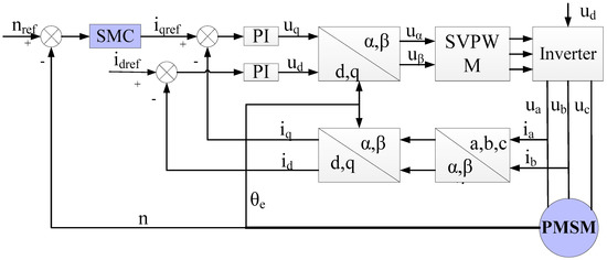
Figure 1.
A typical vector control of permanent magnet synchronous motors (PMSMs).
2.2. SMC Design for the PMSM
It is known that the major drawback of sliding mode control is the so-called chattering phenomenon, which is caused by the high-frequency switching of a sliding mode controller, exciting unmodeled dynamics in the closed loop. This phenomenon indicates that the control signal exhibits high frequency oscillations called chattering after the system state reaches the sliding surface. This chattering can give rise to oscillatory behaviors of unpredictable frequency and can be capable of exciting the system’s resonance modes. Consequently, in sliding mode control applications, there is a need for control strategies to track periodic reference signals or reject periodic disturbances. Repetitive control, which builds on the well-known internal model principle, provides a specialized control scheme for asymptotic tracking and rejection of a periodic exogenous disturbance without steady-state error. Repetitive control has been successfully applied in real industrial applications in the past decades, for example, harmonic suppression of circulating current [28], suppression for exogenous disturbances and uncertainties in the dynamics of a plant [29], and a fast tool servo system [30]. Simultaneously, a repetitive control system can be applied in a plug-in style and has a simple structure formulated by an N-delay positive-feedback loop.
Therefore, a repetitive control is one of the most promising control schemes for enabling perfect rejection of periodic disturbances if periodic chattering disturbances act on the sliding mode control system. To achieve robust and high-accuracy tracking performance, a sliding mode controller combined with a plug-in repetitive compensation controller is proposed in this control scheme. The integrated controller as shown in Figure 2 is designed to stabilize and compensate for the chattering, and the plug-in repetitive controller offers precise tracking performance and harmonic elimination:
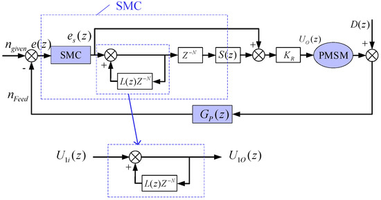
Figure 2.
Block diagram of the improved ding mode control (SMC) strategy.
where a sliding mode control is used as the observer of the repetitive controller, and the chattering generated by the sliding mode control can be stabilized and compensated by the repetitive controller. ngiven is the given speed; nFeed is the feedback speed; e(z) is the error speed; and D(z) is the external disturbance.
As shown in Figure 2, the repetitive controller can be expressed as
The difference expression is rewritten as
where UR0 and URi are the output and the input of the repetitive controller, respectively, as shown in Figure 2. Z−1[] is Z-inverse transformation symbol. () is unit step function.
The Equation (6b) indicates that the output UR0(k) will increase. For L(z) is a low-pass filter, it can attenuate the last output. S(z) is the regulating function for the control object. A detailed discussion on S(z) is beyond the scope of the article, here S(z) = 1.
The configuration of the sliding mode controller is shown in Figure 3.
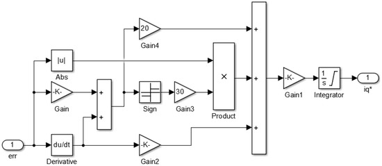
Figure 3.
Configuration of the sliding mode controller.
The state of the controller can be described as
where x1 is the tracking error of speed.
The sliding surface s corresponding to the zero-error manifold is defined as
Differentiating s with respect to time gives
where c and D are positive adjustable parameters, respectively; D = 3pn Ψf/(2J) derived from Equation (5) by making derivative terms transformation in the equation; and x1 and x2 are the state variables, respectively.
To design the sliding-mode controller to ensure better dynamic character and track capability for the non-salient surface-mounted PMSM, the exponential reaching law is adopted as a function of difference between measured current and feedback current. The exponential reaching function can be chosen as
where ε and q are positive adjustable parameters; sgn() represents the signum function.
The output current of the sliding-mode controller can be obtained as
where i*q is the output current of the SMC controller in the q-axis.
2.3. Reachability Analysis
In order to testify that the system state of this sliding mode control can reach the sliding mode surface form arbitrary initial state in limited time, the Lyapunov function candidate is defined as [31].
then the derivation of Lyapunov can be set up with
If c in Equation (9) is a real number, then there will be . Therefore, according to Lyapunov theory, the speed for Equation (7) and can be converged to zero in limited time by designing the sliding mode surface of Equation (9) and control law of Equation (12).
2.4. Stability Analysis
In this section, stability analysis is performed for the proposed control scheme with sliding mode and repetitive control. As shown in Figure 2, the error transfer function e(z) between the feedback speed nFeed and the given speed ngiven can be represented as
where GSMC(z) is the transfer function of the sliding mode control; GP(z) is the sensor transfer function; L(z) is a low-pass filter; KR is a gain coefficient; and D(z) is disturbances.
To verify stability of the proposed SMC, the transfer function of the dynamic disturbance system in Equation (15b) is analyzed, and the sufficient condition is proven as
where S(z) = 1.
In Equation (15b), if the angular frequencies ωm of the disturbance D(z) equals m times, and m is a positive integer, namely, ωm = 0, 1, 2…, this indicates that z−N = 1, and
Thus, the controller can eliminate random harmonic and leads to a better reference speed tracking performance.
3. Simulation and Experiment
Simulations and experimental tests were carried out to investigate the above analysis and to verify the control performance. A laboratory prototype electric drive was used for the experimental validation of the proposed control algorithm. The platform used for the experiments is shown in Figure 4. The system contains a load that attaches to the PMSM, a servo controller, and an encoder. The core of the main control board is a DSP microprocessor; its specific model is TMS320F28335.
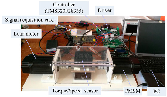
Figure 4.
Experiment platform.
Figure 5 shows the different Simulink simulation results to the input with the system load superposed by ramp signal and step noise signal. As shown in Figure 5a, the speed response curves of the PMSM show that the proposed SMC can track the input more quickly and accurately. Simultaneously, the PMSM can effectively adjust the speed of the rotor to return to stable state according to a sudden load, and the proposed SMC can resume with less time and less speed error.

Figure 5.
Numerical simulation results of different control. (a) Load signal; (b) the rotor speed response of the PMSM.
The PMSM parameters used include the output power Pe = 0.75 kW, rated voltage Ue = 220 V, rated torque Te = 2.4 N·m, max torque Tmax = 7.2 N·m, rated current Ie = 4.2 A, rated speed ne = 2000 r/min, stator phase resistance Rs = 0.901 Ω, pole pairs p = 4, and moment of inertia J = 1.2 × 10⁻⁴ kg·m2. The experimental prototype was built with the same design parameters used in the above simulation. The results of the output performance of the test bench are shown in Figure 6.
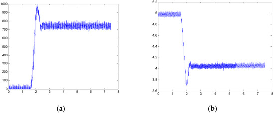
Figure 6.
Configuration of the traditional sliding mode control. (a) The traditional SMC; (b) the proposed SMC.
The actual rotor speed for a traditional SMC during the process of startup and running of the motor is shown in Figure 6a, while Figure 6b shows the corresponding output torque under the same condition. As seen from the pictures, the overshoot is approximately 30% in the process of startup. Simultaneously, there is a large overshoot in the corresponding output torque. Figure 7a,b shows the actual rotor speed and the corresponding torque for the proposed SMC during the startup and running period of the motor, respectively. The results show the speed and torque errors are approximately 7% and 3%, respectively.
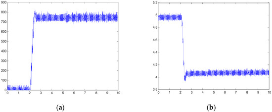
Figure 7.
Configuration of the proposed sliding mode control. (a) The traditional SMC; (b) the proposed SMC.
Figure 8 displays the different results to the input with the system load during the process of running the motor. The deviation of the rotor speed in the traditional SMC is larger than the deviation observed with the proposed SMC. The contrast of the two results shows that the proposed SMC improves the steady state performance and enhances robust stability and disturbance rejection performance.
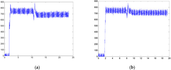
Figure 8.
Configuration of the load disturbance. (a) The traditional SMC; (b) the proposed SMC.
Performance analysis and experimental results demonstrate that the proposed SMC, which combines SMC and repetitive control within an existing feedback control system based on an independent design philosophy, is a superior alternative for reducing the magnitude of transient error and dealing with complicated input signals.
4. Conclusions
This paper described an improved proposed SMC method that incorporates the traditional SMC and repetitive control approach into a PMSM vector control system to improve the disturbance-rejection and tracking performance. A stability criterion for the proposed SMC was derived, and theoretical analysis was conducted to analyze the robustness of the proposed controller. The simulation results showed that the proposed control exhibited satisfactory disturbance-rejection and tracking performance, and the experimental results showed the effectiveness of the proposed control.
Author Contributions
J.Q., C.J. and N.P. conceived the structure of the paper; J.W. analyzed the data; J.Q. and C.J. established the model, validate the model by experiments and wrote the paper.
Funding
Yunnan Applied Basic Research Project: Research on Key Issues of PMSM Nonlinear Control System with Grant Number KKS0201701026.
Conflicts of Interest
The authors declare no conflict of interest.
References
- Qian, J.B.; Yuan, R.B.; Bao, L.P.; Yang, X. Design and optimization of Lorentz motors in a precision active isolator. Int. J. Appl. Electromagn. Mech. 2017, 55, 329–341. [Google Scholar] [CrossRef]
- Kivanc, O.C.; Ozturk, S.B. Sensorless PMSM Drive Based on Stator Feedforward Voltage Estimation Improved with MRAS Multiparameter Estimation. IEEE/ASME Trans. Mechatron. 2018, 23, 1326–1337. [Google Scholar] [CrossRef]
- Zhang, X.; Foo, G.H.B. A constant switching frequency-based direct torque control method for interior permanent-magnet synchronous motor drives. IEEE/ASME Trans. Mechatron. 2016, 21, 1445–1456. [Google Scholar] [CrossRef]
- Sant, A.V.; Rajagopal, K.R. PM synchronous motor speed control using hybrid fuzzy-PI with novel switching functions. IEEE Trans. Magn. 2009, 45, 4672–4675. [Google Scholar] [CrossRef]
- Park, O.S.; Park, J.W.; Bae, C.B.; Kim, J.M. A dead time compensation algorithm of independent multi-phase PMSM with three-dimensional space vector control. J. Power Electron. 2013, 13, 77–85. [Google Scholar] [CrossRef]
- Liu, J.; Li, H.W.; Deng, Y.T. Torque Ripple Minimization of PMSM Based on Robust ILC Via Adaptive Sliding Mode Control. IEEE Trans. Power Eletron. 2018, 33, 3655–3671. [Google Scholar] [CrossRef]
- Fakam, M.; Hecquet, M.; Lanfranchi, V.; Randria, A. Design and magnetic noise reduction of the surface permanent magnet synchronous machine using complex air-gap permeance. IEEE Trans. Magn. 2015, 51, 1–9. [Google Scholar] [CrossRef]
- Lin, F.; Zuo, S.G.; Deng, W.Z.; Wu, S.L. Reduction of vibration and acoustic noise in permanent magnet synchronous motor by optimizing magnetic forces. J. Sound Vib. 2018, 429, 193–205. [Google Scholar] [CrossRef]
- Bartolini, G.; Ferrara, A.; Usai, E.; Utkin, V.I. On Multi-Input Chattering-Free Second-Order Sliding Mode Control. IEEE Trans. Autom. Control 2000, 45, 1711–1717. [Google Scholar] [CrossRef]
- Nakao, N.; Akatsu, K. Suppressing pulsating torques: Torque ripple control for synchronous motors. IEEE Ind. Appl. Mag. 2014, 20, 33–44. [Google Scholar] [CrossRef]
- Cai, J.J.; Lu, Q.F.; Huang, X.Y.; Ye, Y.Y. Thrust Ripple of a Permanent Magnet LSM with Step Skewed Magnets. IEEE Trans. Magn. 2012, 48, 4666–4669. [Google Scholar] [CrossRef]
- Zhu, Z.Q.; Liu, Y. Analysis of Air-Gap Field Modulation and Magnetic Gearing Effect in Fractional-Slot Concentrated-Winding Permanent-Magnet Synchronous Machines. IEEE Trans. Ind. Electron. 2018, 65, 3688–3698. [Google Scholar] [CrossRef]
- Chen, S.Y.; Luo, Y.; Pi, Y.G. PMSM sensorless control with separate control strategies and smooth switch from low speed to high speed. ISA Trans. 2015, 58, 650–658. [Google Scholar] [CrossRef] [PubMed]
- Song, F.Z.; Liu, Y.; Xu, J.X.; Yang, X.; He, P.; Yang, Z. Iterative Learning Identification and Compensation of Space-Periodic Disturbance in PMLSM Systems with Time Delay. IEEE Trans. Ind. Electron. 2018, 65, 7579–7589. [Google Scholar] [CrossRef]
- Qian, R.R.; Luo, M.Z.; Sun, P. Improved nonlinear sliding mode control based on load disturbance observer for permanent magnet synchronous motor servo system. Adv. Mech. Eng. 2016, 8, 1–12. [Google Scholar] [CrossRef]
- Lin, Z.; Pachter, M.; Banda, S. Toward improvement of tracking performance nonlinear feedback for linear system. Int. J. Control 1998, 70, 1–11. [Google Scholar] [CrossRef]
- Mehta, H.; Joshi, V.; Thakar, U.; Kuber, M.; Kurulkar, P. Speed control of PMSM with hall sensors using DSP TMS320f2812. In Proceedings of the IEEE 11th International Conference on Power Electronics and Drive Systems, Sydney, Australia, 9–12 June 2015; pp. 295–300. [Google Scholar]
- Qi, L.; Shi, H. Adaptive position tracking control of permanent magnet synchronous motor based on RBF fast terminal sliding mode control. Neurocomputing 2013, 115, 23–30. [Google Scholar] [CrossRef]
- Xu, W.; Jiang, Y.; Mu, C. Novel composite sliding mode control for PMSM drive system based on disturbance observer. IEEE Trans. Appl. Supercond. 2016, 26, 1–5. [Google Scholar] [CrossRef]
- Li, S.H.; Zhou, M.; Yu, X. Design and implementation of terminal sliding mode control method for PMSM speed regulation system. IEEE Trans. Ind. Inform. 2013, 9, 1879–1891. [Google Scholar] [CrossRef]
- EI-Sousy, F.F.M. Robust adaptive wavelet-neural-network sliding mode speed control for a DSP-based PMSM drive system. J. Power Electron. 2010, 10, 505–517. [Google Scholar] [CrossRef]
- Jung, J.W.; Leu, V.Q.; Dang, D.Q.; Choi, H.H.; Kim, T.H. Sliding mode control of SPMSM drivers-An online gain tuning approach with unknown system parameters. J. Power Electron. 2014, 14, 980–988. [Google Scholar] [CrossRef]
- Caponigro, M.; Ghezzi, R.; Piccoli, B. Regularization of chattering phenomena via bounded variation controls. IEEE Trans. Autom. Control 2018, 63, 2046–2060. [Google Scholar] [CrossRef]
- Su, S.; Wang, H.; Zhang, H.; Liang, Y.; Xiong, W. Reducing Chattering Using Adaptive Exponential Reaching Law. In Proceedings of the Sixth International Conference on Natural Computation (ICNC 2010), Yantai, China, 10–12 August 2010. [Google Scholar]
- Fu, J.; Wang, L.M.; Du, Y.L.; Jun, Z. A Robust Sliding Mode Control for Nonlinear System with Adjustable Chattering Phenomenon. In Proceedings of the 14th International Workshop on Variable Structure Systems (VSS), Nanjing, China, 1–4 June 2016. [Google Scholar]
- Li, S.H.; Zong, K.; Liu, H.X. A composite speed controller based on a second order model of pmsm system. Trans. Inst. Meas. Control 2011, 33, 522–541. [Google Scholar]
- Saeed, M.H.; Ali, J.K.; Mohammad, F. Chattering free fuzzy sliding mode controllers for robot manipulators. In Proceedings of the UKACC International Conference on Control, Coventry, UK, 7–10 September 2010. [Google Scholar]
- Xiong, J.; Fan, S.; He, L.; Zhang, K. A repetitive control scheme for harmonic suppression of circulating current in modular multilevel converters. IEEE Trans. Power Electron. 2015, 30, 471–481. [Google Scholar]
- Yu, P.; Wu, M.; She, J.; Lei, Q. Robust Repetitive Control and Disturbance Rejection Based on Two-Dimensional Model and Equivalent-Input-Disturbance Approach. Asian J. Control 2016, 18, 2325–2335. [Google Scholar] [CrossRef]
- Crudele, M.; Kurfess, T. Implementation of a fast tool servo with repetitive control for diamond turning. Mechatronics 2003, 13, 243–257. [Google Scholar] [CrossRef]
- Zwerger, T.; Mercorelli, P. Combining an Internal SMC with an External MTPA Control Loop for an Interior PMSM. In Proceedings of the 2018 23rd International Conference on Methods & Models in Automation & Robotics (MMAR), Miedzyzdroje, Poland, 27–30 August 2018; pp. 674–679. [Google Scholar]
© 2018 by the authors. Licensee MDPI, Basel, Switzerland. This article is an open access article distributed under the terms and conditions of the Creative Commons Attribution (CC BY) license (http://creativecommons.org/licenses/by/4.0/).