Abstract
The task of control of unmanned helicopters is rather complicated in the presence of parametric uncertainties and measurement noises. This paper presents an adaptive model feedback control algorithm for an unmanned helicopter stability augmentation system. The proposed algorithm can achieve a guaranteed model reference tracking performance and speed up the convergence rates of adjustable parameters, even when the plant parameters vary rapidly. Moreover, the model feedback strategy in the algorithm further contributes to the improvement in the control quality of the stability augmentation system in the case of low signal to noise ratios, mainly because the model feedback path is noise free. The effectiveness and superiority of the proposed algorithm are demonstrated through a series of tests.
1. Introduction
It is essential that the flight control system of an unmanned helicopter (UH) should be endowed with well-suited automatic capabilities to carry out flight missions. However, the flight performance of an UH is intimately dependent on the stability and control characteristics of the UH [1,2]. Unlike some mechanical systems with desirable structural properties, UH is normally an inherently unstable system without stability augmentation control strategy. Furthermore, some of the aerodynamic parameters vary with flight environments or system conditions, with the result that it is very difficult to design the stability augmentation system for an UH using the conventional control methods [3].
UH is also a complicated nonlinear dynamic system described by nonlinear differential equations. However, for simplicity in the design of controllers for an UH, the linearized models are normally derived from nonlinear differential equations if the UH operates around an operating point. Many linear control techniques for application to UH flight control systems have been proposed in literature, among which single-input, single-output (SISO) feedback control methods are by far the most common choices with few dependencies on dynamic models. In [4], a SISO PD control law is adopted and further optimized for both hovering and forward flight of the CMU-R50 UH. In [5], a SISO PID control law is implemented for automatic hovering of the Ursa Major 3 UH. The above SISO methods have the advantages of conceptual and computational simplicity. However they may decrease the stability and control qualities of UHs without considering parametric uncertainties and cross-couplings among axes.
Therefore, in order to improve the flight performance, a lot of research effort has been devoted to the design of advanced stability augmentation systems. Previous research reported in the literature includes gain scheduling [6], linear-quadratic regulation (LQR) or linear-quadratic Gaussian (LQG) approach [7], decentralized decoupled model predictive approach [8] and intelligent control methods like neural network [9] and fuzzy logic approach [10], etc. Several flight control systems using H∞ control methods, which can provide the robust stability and performance for the systems subject to uncertainties and disturbances, have been designed for mini UHs. In [11], a H∞ loop shaping technique is utilized for the stability augmentation system of Bell-205 helicopter. Mixed-norm optimization and weighted H∞ mixed sensitivity optimization methods are respectively designed to improve the stability and maneuverability characteristics of UHs [12,13]. Although these methods have achieved acceptable flight performance, they still rely heavily on the plant model. More importantly, the above-mentioned methods fail to consider the adverse effects of parametric uncertainties and measurement noises on the flying qualities. Some existing adaptive techniques can accommodate the parametric uncertainties more effectively without considering measurement noises [14,15,16,17,18]. A novel modified model reference adaptive control (MRAC) strategy is developed with added noise [19]. However, this method only reduces the noise disturbance using a low-pass filter. Usually in practical use, those existing adaptive control methods can hardly minimize the adverse effect of measurement noises on the flying qualities. The NASA Marshall Space Flight Center has developed an adaptive augmenting control (AAC) algorithm for launch vehicles by adapting a well tuned classical control algorithm to unexpected environments or variations in vehicle dynamics. The AAC algorithm has been successfully tested in a relevant environment. However it needs to be further evaluated by the flight tests [20].
The essential parameter regulation schemes can reduce the complexity of a high performance control system design problem in the presence of parametric uncertainties and measurement noises. On this basis, this study aims to develop an adaptive model feedback control algorithm for a prototype unmanned helicopter stability augmentation system. The proposed adaptive algorithm can achieve a guaranteed model reference tracking performance and speed up the convergence rates of adjustable parameters, even when the plant parameters vary rapidly. Moreover, the model feedback control strategy in the algorithm can further improve the control quality of the stability augmentation system because the model feedback path is noise free. The experimental setups and the actual flight test results using the proposed algorithm are shown and the results are discussed.
This paper describes the control problem for the prototype UH stability augmentation system in Section 2. The adaptive model feedback control algorithm for the prototype UH stability augmentation system is presented in Section 3, and Section 4 provides the improvement of the algorithm. The flight test results are shown in Section 5. Finally, conclusions are drawn in Section 6.
2. The Control Problem for the Prototype UH Stability Augmentation System
The prototype UH, with net weight 180 Kg and height 1.9 m, is a vertical takeoff and landing aircraft which includes two coaxial rotors and a fuselage with toroidal portion, as shown in Figure 1. A duct is formed through the fuselage. A propeller assembly is mounted to the top portion of the fuselage with a main rotor, 4.4 m in diameter, above the fuselage. A ducted rotor assembly in fuselage is used to compensate the propeller antitorque as well as providing some fraction of lift. The coaxial rotors, main and ducted, rotate at 800 rpm in the opposite directions with the main rotor providing about 70% of lift, drag, and pitch and roll movements of UH and the ducted rotor providing about 30% of lift and yaw movement.
Figure 1.
The prototype unmanned helicopter.
The stability augmentation system design for the prototype UH is a challenging task because the UH dynamics are highly nonlinear and subject to parametric uncertainties. In addition, the plant parameters change with the flight environments (e.g., the aerodynamic constants) or the system conditions (e.g., lift curve slopes). The adaptive control strategy is adopted to solve the above problems in this study.
By assuming that the fuselage is a rigid body and the main rotor speed is constant, we can describe the nonlinear kinematic equations associated with the six degrees of freedom (6-DOF) as an equivalent block in the following manner:
where and represent the state vector and the control vector, respectively; represents the unsteady aerodynamic parameters set, which is difficult and expensive to measure and is, therefore, not available in most cases. Of the state variables in , here are forward velocity, lateral velocity and vertical velocity, respectively; are pitch angle, roll angle and yaw angle, respectively; are pitch rate, roll rate and yaw rate, respectively; are pitch cyclic, roll cyclic, ducted rotor collective and main rotor collective, respectively.
One common method to solve the control problem for the nonlinear system in Equation (1) is through linearization. The linearized model about a trim condition of the nonlinear dynamics is then represented as
where and are the increments at a specified trim condition; and are the system matrix and the control-input matrix, respectively. Accordingly, and are respectively the trim state and the trim input with respect to hovering, lifting or forward flight, which must satisfy the equation
Note that and , obtained by solving Equation (3), are unknown as well. Therefore, we define
and can also be regarded as the estimates of and , respectively. Equation (2) can then be rewritten as:
where and . is equivalent to an unknown input disturbance at the trim condition.
To avoid repetition, the present study is only focused on the stability augmentation system of the longitudinal axis to demonstrate the proposed adaptive algorithm, which, without loss of generality, can apply to other axes. Thus, referring to Equation (5), the linearized model of the longitudinal axis can be denoted by:
where and represent the unknown time-varying aerodynamic parameters; is the corresponding component of the vector .
Given the corresponding wind tunnel test data, the effect of and on is negligible and can therefore be ignored, the linearized model of longitudinal axis can then be simplified as follows:
Overall, the complexity of the stability augmentation system design originates mainly from the parametric uncertainties together with measurement noises.
3. Design of the Stability Augmentation System Based on an Adaptive Model Feedback Control Algorithm
3.1. Theorem 1
Consider the plant of the form of Equation (7), with and . Assume that
where
and where and are adjustable parameters; is the output of the ideal decoupled model given by:
and denote the model parameters determined according to ADS-33, the manipulated input. Thus, asymptotically converge to as the adaptive laws are given by:
where and are greater than zero; represents and , respectively; the tracking error is defined as:
the time-varying parameter should satisfy the following constraint:
the generalized input is denoted by:
3.2. Proof
Substituting Equation (14) into Equation (8) yields
Again the generalized plant shown in Equation (16) is derived by substituting Equation (15) into Equation (7).
where .
Similarly, we have
Then, substituting Equations (16) and (17) into Equation (12) yields:
where
Furthermore, the adaptive laws are chosen so that certain stability conditions based on Lyapunov theory are satisfied. Consider the Lyapunov function candidate
where and are greater than zero. We can therefore conclude that is negative definite as
in which represents and , respectively. From Equations (19) and (21), we can easily deduce the adaptive laws given by Equation (11).
3.3. Remarks
i. The direct addition of an external feedback term like to is necessary without any modification of the adaptive laws if cannot satisfy at a certain flight condition, where is used to guarantee the stability of the plant, that is, in this case.
ii. In consideration of the adverse effect of measurement noises, the variance of the noise component of can be reduced while using the proposed adaptive algorithm, mainly because the model feedback path is noise free, which can result in the improvement in the control quality of the stability augmentation system, especially in the case of low signal to noise ratios (SNR).
iii. Compared to the model reference adaptive control (MRAC) method, the additional time-varying parameter in the proposed algorithm can contribute to the convergence rates of adjustable parameters when the plant parameters vary rapidly.
4. The Improvement and Application of the Adaptive Laws
The adaptive laws are difficult to apply in practice because is non-measurable in most cases. According to linear system theory, Equation (18) can be rewritten as follows:
where and are respectively served as the outputs of an arbitrarily chosen filter in response to and . The adaptive laws, derived by using the similar Lyapunov function described in Equation (20), are rewritten as:
where satisfies the following constraint:
The improved adaptive laws are therefore subject to a certain form of the filter. Assume that the filter transfer function is given by:
where is the time constant. In this case, Equation (24) can be written as:
which indicates that is available. Figure 2 shows the schematic diagram of the adaptive stability augmentation system with model feedback. Note that the proper choice of can speed up the convergence of adjustable parameters.
Figure 2.
The schematic diagram of the adaptive stability augmentation system.
Note that and are completely dominant over other adjustable parameters in Equation (8), however the noise component of can be ignored on the basis of the assumption that the manipulated input is noise free. For , the adaptive model feedback strategy can therefore lead to a marked loss in noises.
5. Flight Tests
In this section, the performance of the proposed algorithm is demonstrated for the stability augmentation system of the longitudinal axis. All pre-chosen parameters are given as follows:
- (1)
- The model parameters: and ;
- (2)
- The initial values of adjustable parameters: and are assumed to equal zero, and ;
- (3)
- The time constant of the filter: ;
- (4)
- The parameters of the adaptive control laws: ; ; .
The proposed algorithm is first implemented in a numerical simulation based on the nonlinear helicopter model. It is then applied to the prototype UH to evaluate the flight performance of the stability augmentation system.
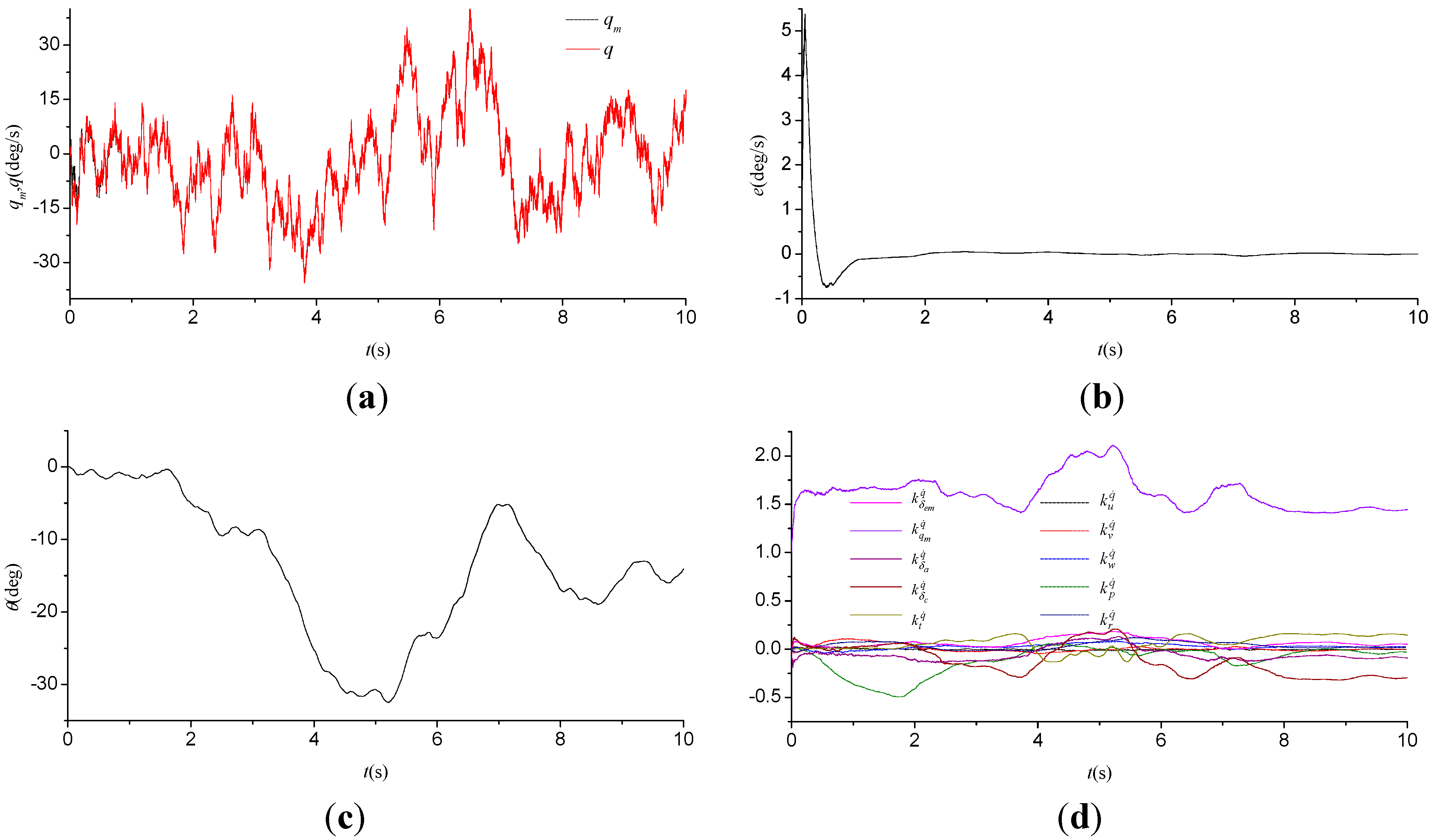
5.1. Task 1: Numerical Simulation
Figure 3.
Numerical simulation results of the proposed algorithm. (a) and ; (b) ; (c) ; (d) Adjustable parameters.
The numerical simulation test, shown in Figure 3, is conducted using the nonlinear dynamics model of the prototype unmanned helicopter, together with a simplified closed-form trim calculation. The manipulated input signal is generated from a joystick device. Various moderately aggressive maneuvers are conducted during the simulation to evaluate the performance of the proposed algorithm at different operate points of the flight envelope. A comparison is made between the output of the plant and that of the model, as shown in Figure 3a,b, which demonstrates that the tracking error can rapidly approach zero in 0.9 s and remain in a bounded range. We can therefore conclude that the proposed adaptive algorithm achieves a guaranteed model reference tracking performance and has a good convergence property. The tracking error remains in a bounded range even though the adjustable parameters vary rapidly during the test. However the conventional MRAC approach is not applicable to the case where the variations of the plant parameters are significant.
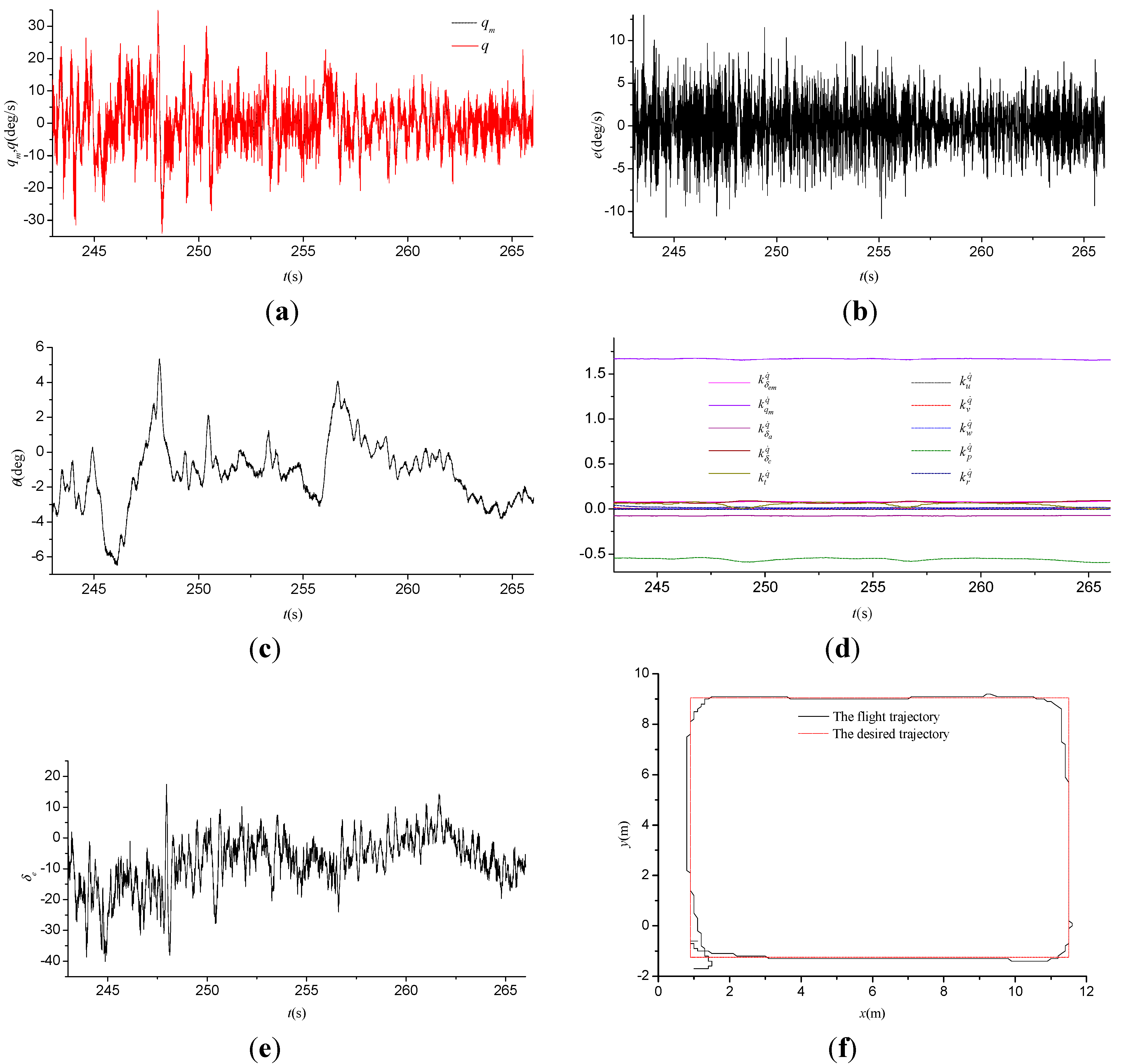
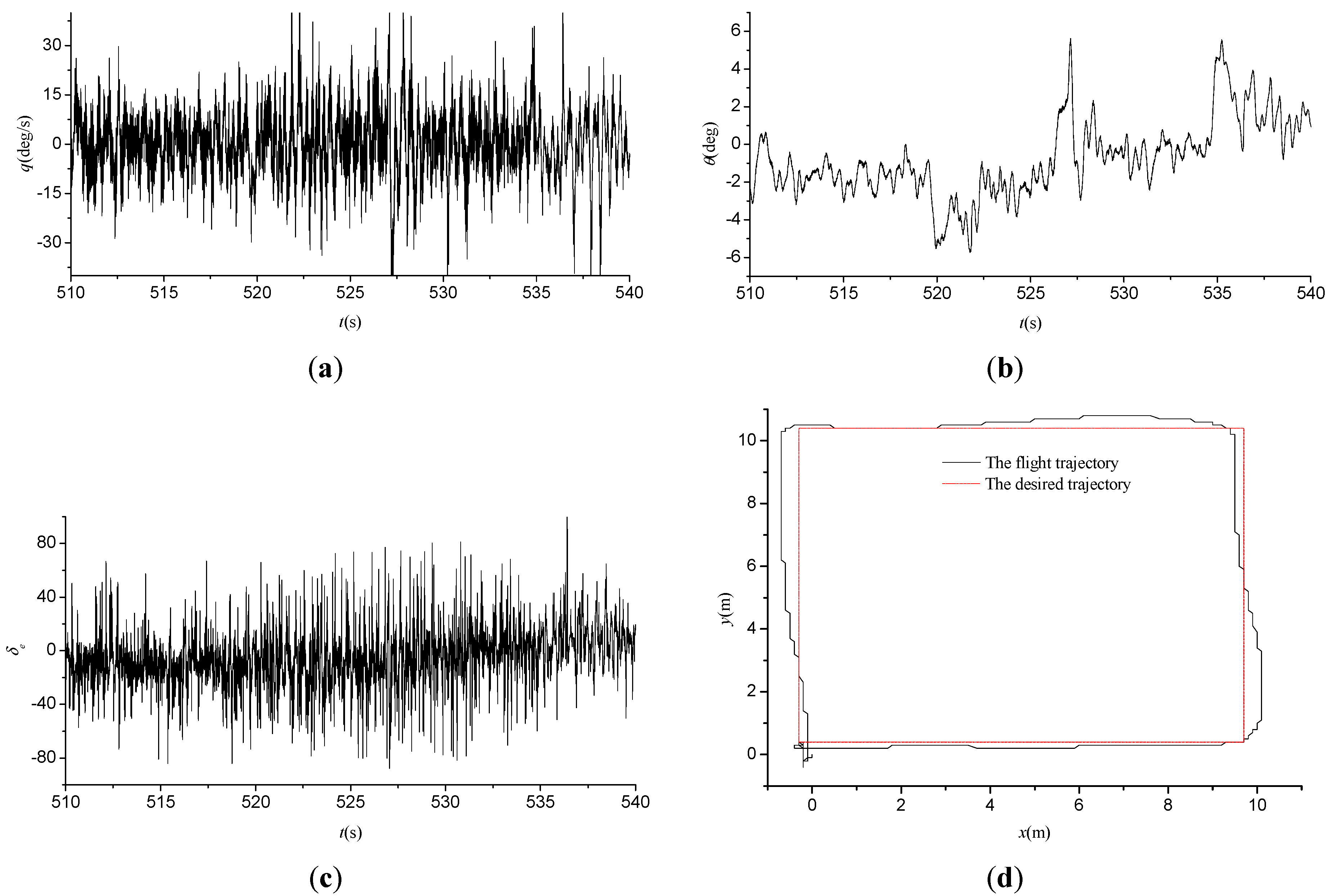
5.2. Task 2: Flight Tests
Figure 4.
Flight test results of the proposed algorithm. (a) and ; (b) ; (c) ; (d) Adjustable parameters; (e) ; (f) The ground track view of trajectory.
The flight tests are conducted to compare the performance of the proposed algorithm with that of the conventional PID while those two approaches applies to the prototype unmanned helicopter stability augmentation system, respectively. For a fair comparison, the attitude and position controllers remain unchanged. Our control software system, which runs on a DSP-based hardware platform with a control period of 10 ms, can provide reliable support for high precision timer and synchronization operations. The sensors (including an AHRS unit and a DGPS unit) are used to provide the information related to the flight status, such as the angles, angular rates, velocity and position. During flight, Wi-Fi and serial-based data links provide a link to the ground station computer that allows monitoring the real-time flight information and uploading remote control commands such as way points. Testing of the proposed adaptive algorithm begins with hover, followed by simple way-point navigation due to the limitations of the test conditions such as flight safety. In consideration of measurement noises of the sensors, the results from these flight tests are provided in Figure 4 and Figure 5.
The performance of the adaptive stability augmentation system is first evaluated at low speeds where a square pattern is flown, as shown in Figure 4. The noisy tracking error, shown in Figure 4b, is also within an acceptable range. Moreover, the model feedback strategy in the proposed algorithm contributes to the restricted variation of the control signal shown in Figure 4e, which explicitly improves the external command position tracking performance, and implicitly demonstrates the improvement in the control quality of the stability augmentation system.
Figure 5.
Flight test results of the PID controller. (a) ; (b) ; (c) ; (d) The ground track view of trajectory.
By comparison with the above-mentioned results, the flight test results of the conventional PID controller implemented through the widely used Pixhawk autopilot module, shown in Figure 5, appear to deteriorate. For instance, the variation of the control signal , together with the external command position tracking errors, increases when the prototype UH is commanded to perform the same flight mission.
Based on the flight test results, we can conclude that the proposed adaptive model feedback control algorithm is able to adapt to rapidly changing flight conditions and effectively enhance the performance of the prototype UH stability augmentation system in the presence of parametric uncertainties and measurement noises, which results in the improvement in flying qualities. More significantly, most existing designs would require accurate models at each point, while the proposed design does not.
6. Conclusions
This paper presents the adaptive model feedback control algorithm for the prototype UH stability augmentation system in the presence of parametric uncertainties and measurement noises. The proposed adaptive algorithm is able to achieve a guaranteed model reference tracking performance and speed up the convergence rates of adjustable parameters, even when the plant parameters vary rapidly. Moreover, the model feedback strategy in the proposed algorithm further contributes to the improvement in the control quality of the stability augmentation system in the case of low SNR. The flight test results have shown that the proposed algorithm can considerably improve the flying qualities of the prototype UH.
Acknowledgments
This study was supported in part by National Natural Science Foundation of China (NSFC) (Under Grant No. 61374188), Aeronautical Science Foundation of China (Under Grant No. 2013ZC52033), Natural Science Foundation of Jiangsu Province of China (Under Grant No. BK20141412).
Author Contributions
All authors discussed the contents of the manuscript. Shouzhao Sheng contributed to the research idea and the framework of this study. Chenwu Sun performed the experimental work.
Conflicts of Interest
The authors declare no conflict of interest.
References
- Cai, G.; Chen, B.M.; Lee, T.H. Unmanned Rotorcraft Systems, 1st ed.; Springer: New York, NY, USA, 2011. [Google Scholar]
- Ren, B.; Ge, S.S.; Chen, C.; Fua, C.H.; Lee, T.H. Modeling, Control and Coordination of Helicopter Systems, 1st ed.; Springer: New York, NY, USA, 2012. [Google Scholar]
- Cook, M.V. Flight Dynamics Principles: A Linear Systems Approach to Aircraft Stability and Control, 3rd ed.; Butterworth-heinemann: Oxford, UK, 2012. [Google Scholar]
- Mettler, B. Identification Modeling and Characteristics of Miniature Rotorcraft, 1st ed.; Springer: New York, NY, USA, 2011. [Google Scholar]
- Shim, D.H.; Kim, H.J.; Sastry, S. Control System Design for Rotorcraft-Based Unmanned Aerial Vehicles Using Time-Domain System Identification. In Control Applications, Proceedings of the 2000 IEEE International Conference on, Anchorage, AK, USA, 25–27 September 2000; pp. 808–813.
- Takahashi, M.; Schulein, G.; Whalley, M. Flight Control Law Design and Development for an Autonomous Rotorcraft. In Proceedings of the 64th Annual Forum of the American Helicopter Society, Montreal, Quebec, Canada, 29 April–1 May 2008; pp. 1652–1671.
- How, J.; Bethke, B.; Frank, A.; Dale, D.; Vian, J. Real time indoor autonomous vehicle test environment. IEEE Control Syst. Mag. 2008, 28, 51–64. [Google Scholar] [CrossRef]
- Shim, D.H.; Kim, H.J.; Sastry, S. Decentralized Nonlinear Model Predictive Control of Multiple Flying Robots. In Decision and Control, Proceedings of 42nd IEEE Conference on, Maui, HI, USA, December 2003; pp. 3621–3626.
- Buskey, G.; Wyeth, G.; Roberts, J. Autonomous Helicopter Hover Using an Artificial Neural Network. In Proceedings of the IEEE Conference on Robotics and Automation, Seoul, Korea, 21–26 May 2001; pp. 1635–1640.
- Garcia, R.; Valavanis, K. The implementation of an autonomous helicopter testbed. J. Intell. Robot. Syst. 2009, 54, 423–454. [Google Scholar] [CrossRef]
- Smerlas, A.J.; Walker, D.J.; Postlethwaite, I.; Strange, M.E.; Howitt, J.; Gubbels, A.W. Evaluating H∞ controllers on the NRC Bell 205 fly-by-wire helicopter. Control Eng. Pract. 2001, 9, 1–10. [Google Scholar] [CrossRef]
- Walker, D.J. Multivariable control of the longitudinal and lateral dynamics of a fly-by-wire helicopter. Control Eng. Pract. 2003, 11, 781–795. [Google Scholar] [CrossRef]
- Gadewadikar, J.; Lewis, F.; Subbarao, K.; Chen, B.M. Structured H-infinity command and control-loop design for unmanned helicopters. J. Guid. Control Dynam. 2008, 31, 1093–1102. [Google Scholar] [CrossRef]
- Dytek, Z.T. Adaptive Control of Unmanned Aerial Systems. Ph.D. Thesis, Massachusetts Institute of Technology, Cambridge, MA, USA, September 2010. [Google Scholar]
- Krupadanam, A.S.; Annaswamy, A.M.; Mangoubi, R.S. Multivariable adaptive control design with applications to autonomous helicopters. J. Guid. Control Dynam. 2002, 25, 843–851. [Google Scholar] [CrossRef]
- Liu, Y.; Tao, G. Modeling and model reference adaptive control of aircraft with asymmetric damage. J. Guid. Control Dynam. 2010, 33, 1500–1517. [Google Scholar] [CrossRef]
- Dauer, J.C.; Faulwasser, T.; Lorenz, S.; Findeisen, R. Optimization-Based Feed Forward Path Following for Model Reference Adaptive Control of an Unmanned Helicopter. In Proceedings of the AIAA Guidance, Navigation, and Control Conference, Boston, MA, USA, 19–22 August 2013.
- Rusnak, I.; Weiss, H.; Barkana, I. Improving the performance of existing missile autopilot using simple adaptive control. Int. J. Adapt Control Signal Process. 2014, 28, 732–749. [Google Scholar] [CrossRef]
- Neild, S.A.; Yang, L.; Wagg, D.J. A modified model reference adaptive control approach for systems with noise or unmodelled dynamics. Proc. Inst. Mech. Eng., Part I: J. Syst. Control Eng. 2008, 222, 197–208. [Google Scholar] [CrossRef]
- VanZwieten, T.; Gilligan, E.; Wall, J.; Orr, J.; Miller, C.; Hanson, C. Adaptive Augmenting Control Flight Characterization Experiment on an F/A-18. In Proceedings of American Astronautical Society Guidance & Control Conference, Breckenridge, CO, USA, 31 January–5 February 2014; Volume 1, pp. 1–17.
© 2015 by the authors; licensee MDPI, Basel, Switzerland. This article is an open access article distributed under the terms and conditions of the Creative Commons Attribution license (http://creativecommons.org/licenses/by/4.0/).