Abstract
The primary objective of this work is to provide new solutions to increase impact protection, using a three-dimensional textile imbibed with a shear-thinning fluid. An extensive analysis showed a scarcity of research papers related to the damping capacity of deformable porous materials imbibed with non-Newtonian fluid. No studies were found for shear-thinning fluid flow inside highly compressible foams or other soft, porous materials. The damping capacity of the imbibed material was evaluated using impact with a dropping weight. Polyvinyl alcohol solution mixed with water was used for imbibition of a three-dimensional textile. Hydrophilized carbon nanofibers were also added to the solution to augment the shear-thinning behavior. The measured impact force for imbibed samples showed an important reduction compared to the impact force for the dry material. This research does not focus on flow phenomena at the microstructural level but instead aims to highlight the macroscopic attenuation effect that occurs during the compression of the imbibed material.
1. Introduction
Porous materials have important impact-damping properties and are widely used in our daily life. They are available in a large variety of materials (foams, textiles, woven or non-woven, etc.) which can be obtained from natural sources or synthetized. In recent years, highly compressible porous materials gained interest in various studies focused on high impact energy. The solid structure of the porous materials can absorb energy when deformed due to mechanical impact [1]. Elastoplastic bending of walls of cellular solids [2], buckling or shearing of the filaments and contacting between filaments of textiles [3] contribute to the overall damping energy and influence the material response when compressed. Early studies ignored the presence of the air inside the pores [2], but for higher strain rates the influence of gas must be considered [4,5]. Liquids, when used to imbibe porous materials, play a more important role in their dynamic behavior [6,7,8]. Models such as Darcy–Brinkman and other porosity–permeability formulations have been particularly useful in describing flow, even in high-porosity structures.
Typical materials used for impact-damping applications are reticulated foams or textiles materials (woven or nonwoven), with an initial porosity around 0.9 or greater [9,10]. Permeability variation during compression is one of the key factors in generating lift effects. This type of damping mechanism opens new research directions. The envisioned applications are sports equipment, damping systems for the automotive industry (i.e., collision systems, shock absorbers, etc.) and protective equipment for medium and high impact energy. A similar mechanism can be found inside human joints, where a naturally produced fluid—the synovial fluid—imbibes a porous cartilage [7]. According to ex-poro-hydrodynamic (XPHD) lubrication theory developed by Pascovici and Cicone [7], the resistance to flow inside the porous material generates an important load-carrying capacity. The resistance to flow increases during compression due to decreasing porosity and permeability [11]. During impact, the soft, porous materials imbibed with fluids are compressed rapidly, and for high impact energies the voids collapse simultaneously, squeezing out the fluid [9], usually in a different direction. In one of the first published studies, Hilyard [12] provided a third-order, nonlinear equation of motion to understand the contribution of fluid flow to the impact behavior of open-cell foams. More recently, Dawson et al. [6] presented a tractable model to describe fluid contribution under dynamic compression for high-porosity, low-density, reticulated foams imbibed with a Newtonian fluid. Cicone et al. [13] revealed that under impact compression there is an optimal initial porosity of the porous layer that minimizes the peak impact force, which is a key factor governing the effect on the impacted structure.
The need for protective equipment for hazardous recreational activities or for personnel handling high-risk activities could justify further investigation into the effect of the presence of fluids inside the porous structures and their response under dynamic compression. Undoubtedly, military regulations impose severe conditions in the design of ballistic protection, but the modern war in Ukraine can galvanize the research for unprecedented new solutions. Two research directions can be underlined related to the usage of non-Newtonian fluids for impact protection: the flow of shear-thickening (dilatant) fluids inside porous materials (when subjected to compression the viscosity increase with the shear rate will instantly create an opposite force) and the flow of shear-thinning (pseudoplastic) fluids inside porous materials (the viscosity decrease with the shear rate and by fluid flow fostering the impact force is damped).
An extensive analysis of the published experimental results for non-Newtonian flow inside porous structures reveals that most of the studies are dedicated to geological applications [14] for rocks and soil. Most of the existing work on shear-dependent flow in porous structures originates from enhanced oil recovery, where polymer solutions permeate geological media [15], which is a rigid porous matrix. Significant interest exists in studying blood flow through porous structures for biomedical applications [16], and experimental methods continue to advance in filtration and mold-injection industries. However, we found a scarcity of studies related to the damping capacity of deformable porous materials imbibed with non-Newtonian fluid flow. The study by Dowson et al. [17] is one of few that focuses on elastomeric foam filled with colloidal silica under dynamic compression, where the fluid behaves as a shear-thickening fluid under dynamic flow conditions. A distinct and extensively studied category concerns ballistic woven fabrics and the enhancement of their performance through imbibition with shear-thickening fluids [18,19,20,21,22,23,24]. In contrast, a comprehensive survey of the literature published over the past five years across major scientific databases revealed no studies addressing shear-thinning fluids in soft, porous materials for impact applications.
Given the growing interest in lightweight, flexible and tunable protective systems, understanding the mechanics of shear-thinning fluids within deformable porous architectures is essential. Under rapid compression, the porous channels narrow significantly, increasing local shear rates within the fluid while reducing viscosity. This viscosity reduction facilitates sustained radial fluid flow through progressively narrowing porous channels, even at high compressive strains. Consequently, viscous dissipation is maintained, delaying premature stiffening leading to reduced peak impact forces and enhanced energy-absorption efficiency. Despite the relevance of this mechanism, no studies have investigated shear-thinning flow within deformable porous materials under dynamic compression.
The lack of recent studies in this area motivates the present work, which focuses on the coupled damping behavior of shear-thinning fluids and porous materials. More accurately, the objective of this study is to examine the dynamic impact response of a 3D spacer textile imbibed with a shear-thinning polyvinyl-alcohol–carbon-nanofiber solution. The use of three-dimensional fabrics has gained interest, especially in cushioning or impact-damping applications [25,26]. Understanding the contribution of the fluid was approached using the assumptions of ex-poro-hydrodynamic lubrication. Using controlled drop-weight experiments, we evaluated the overall ability of the shear-thinning fluid to contribute to energy absorption and impact-force reduction for different concentrations of the carbon nanofiber additive. The influence of textile structural parameters and the interaction between fibrous structure and the fluid was not analyzed in detail. Moreover, this paper discusses and compares the observed response with known mechanisms in shear-thickening systems. The present work provides one of the first experimental demonstrations of shear-thinning-assisted damping in highly compressible porous foams.
2. Materials and Methods
2.1. Polyvinyl Alcohol Solution
Polyvinyl alcohol (average Mw 85,000–124,000, 87–89% hydrolyzed), pyrolytically stripped conical carbon nanofiber platelets (>98% carbon basis, dimensions: diameter × length = 100 nm × 20–200 µm), nitric acid (concentration 68%), sulfuric acid (concentration 95–98%), sodium hydroxide, all produced by Aldrich, were used as received.
The hydrophilized carbon nanofibers (CNF-OH) were prepared according to a modified oxidation method. Two grams of carbon nanofibers were dispersed in 60 mL of sulfuric acid, then 20 mL of nitric acid was slowly added, and the reaction mixture was stirred for 2 h. Then, 200 mL of water was added dropwise, and the reaction mixture was cooled down under stirring conditions before the addition of another 400 mL of water. The reaction mixture was finally neutralized using sodium hydroxide until pH = 7 was achieved, and the obtained CNF-OH were separated by filtration and washed thoroughly with water.
The preparation of the polyvinyl alcohol solution (PVA-S) and of polyvinyl alcohol solution with hydrophilized carbon nanofibers (PVA-S CNF-OH) nanocomposite dispersions involved the use of a high shear mixing/dispersing homogenizer (Ika T8 Ultra Turrax Homogenizer, manufactured by IKA Laboratory Equipment, Staufen, Germany). The polyvinyl alcohol was slowly added to the distilled water at a stirring rate of 15,000 rpm. The prepared volume of solution/dispersion was 500 mL. The concentration of polyvinyl alcohol in the water solution (PVA-S) was set at 9% (weight %).
Raman spectroscopy was performed on the modified CNF to confirm the chemical modification (Figure 1). Raman spectra of the functionalized graphene were recorded on a DXR Raman Microscope (manufactured by Thermo Electron Scientific Instruments LLC, Madison, WI, USA) by a 473 nm laser line. The “10×” objective was used to focus the Raman microscope. The rheological behavior of the solutions was analyzed on an Anton Paar MCR 702 rheometer (Anton Paar, Graz, Austria) using the cone-plane method. The analysis revealed that the intensity ratio between the D band (ID = 1356 cm−1) and G band (IG = 1575 cm−1) increases from 0.46 to 0.48, confirming controlled functionalization of CNF-OH, consistent with the targeted low degree of surface modification [27,28].
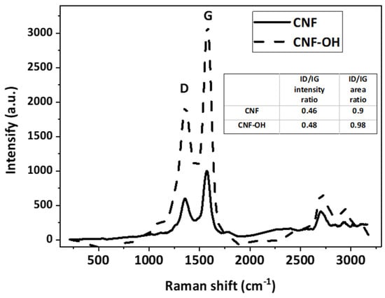
Figure 1.
Raman spectra for the unmodified and for the synthesized hydrophilic CNF-OH nanofiller.
The use of water as a solvent offers a greater economic advantage. Polyvinyl alcohol offers several advantages: it is biodegradable and biocompatible (it has a low protein adhesion and toxicity); it is soluble in water, colorless and odorless; and it is widely used, making it easily accessible. The nanofiller’s effect on solution viscosity depends on nanotube shape, size, temperature at use, concentration and other specific properties. CNF-OH were used in PVA-S to obtain three different concentrations: 0.1%, 0.2% and 0.4% (weight %). The viscosity behavior of the PVA-S is influenced by the presence of both intermolecular and intramolecular hydrogen bonds [29,30]. The hydrolysis degree, concentration and molecular weight critically affect the rheological properties of PVA-S [31]. During the preparation of the CNF-OH nanofiller dispersion in PVA-S, a high shear force was applied, which makes it possible to obtain a morphology involving the intercalation of CNF-OH between the polyvinyl alcohol polymer chains. The modification of CNF with functional groups such as -OH and -COOH permits the formation of hydrogen bonds with the polyvinyl alcohol polymer chains and facilitates dispersion in water. The application of a high shear rate to the PVA-S with the nanofiller CNF-OH results in a decrease in viscosity with shear rate. This behavior is specific for non-Newtonian fluids [32], with the dispersion presenting pseudoplastic behavior. Many gels and colloids are pseudoplastic thixotropic materials, stable at rest but fluid when agitated, exhibiting a reversible gel–sol transformation phenomenon. Fluid thixotropy is not of interest for the current study because of the short shearing period.
The selection of carbon nanofibers (CNF-OH) is based on three characteristics: (i) their high aspect ratio (small diameter relative to length) with micrometer-scale lengths that facilitate intercalation and physical entanglement with PVA chains during high shear mixing; (ii) their surface chemistry, in which polar -OH/-COOH functional groups enable hydrogen bonding with partially hydrolyzed PVA (87–89%), thereby modifying the low shear viscosity and enabling tunable shear-thinning behavior; and (iii) in comparison with plate-like graphene or spherical silica, CNFs avoid excessive low shear gelation at modest loadings while still maintaining percolated micro networks that are conducive to energy dissipation under compression.
The rheological behavior of the solutions was analyzed using the cone-plane method. Water and polymer solutions are known to be shear-thinning. Figure 2 shows viscosity measurements vs. shear rate for the solution with and without CNF-OH at concentrations of 0.1%, 0.2% and 0.4%. The addition of CNF-OH to the PVA-S substantially influences the viscosity at low shear rates. For the 0.4% concentration of CNF-OH, the solution behaves like a gel and performs better when the samples are imbibed. The viscosity variations for all solutions were fitted using a simple power law, and the specific coefficients used to describe the shear stress (τ)—shear rate () relation are presented in Table 1.
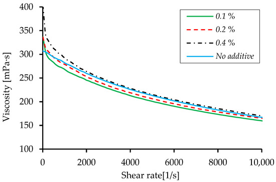
Figure 2.
Viscosity vs. shear rate for all PVA-S with nanofiller CNF-OH.

Table 1.
Power law coefficients after fitting viscosity measurements for all solutions.
2.2. Three-Dimensional Textile
The three-dimensional textiles in dry conditions have a proven capacity to damp impact energy [13,33,34], and studies show that this capacity is significantly improved when imbibed with liquids [13]. A single type of porous material was used during experiments, a three-dimensional textile (3D Spacer, produced by Heathcoat Fabrics, Tiverton, UK) (Figure 3). The material is warp-knitted with a structure of vertical monofilament yarns that joins together two faces at a certain distance. Their internal structure was studied by Lupu et al. [34,35], revealing that the diameter of the vertical yarn is d = 150 μm. The two sides are made of the same material but woven differently, and one of the sides has large holes. Generally, the entire structure stability and its compression response are influenced by the distance between the two faces. The total thickness of this material is h0 = 6.45 mm, with the faces having different thickness: 0.85 mm and 0.645 mm.
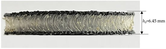
Figure 3.
Internal structure of 3D Spacer.
Discs of radius r0 = 19 mm were laser cut and then imbibed with the solution using a syringe. During imbibition the discs were weighed. Based on the initial porosity of the material ε0 = 0.907, the total volume of voids per disc sample was calculated as Vvoids = 6.635 mL, while for imbibition a rounded value of 7 mL was used. Maintaining complete imbibition under the experimental conditions proved challenging primarily due to gravity-driven drainage; therefore, partially imbibed samples with a controlled and constant imbibition level of imbibition were used. The solution was added slowly on top of the sample, and it was observed that the solution flows outside the inter-fiber voids due to gravity, before reaching full imbibition. The solution remained on the scale after imbibition was recorded. Based on this information, a level of imbibition of ≈75–85% was achieved. After impact, all the discs were weighed again, showing ≈40–50% remaining imbibition.
The 3D Spacer was subjected to preliminary constant velocity compression tests, carried out on the Zwick/Roell Z010 TN universal testing machine (Zwick Roell Group, Ulm, Germany). The tests were performed on new samples each time in similar conditions at room temperature, with a low compression speed of 0.5 mm/s. The variation in the force with displacement was recorded. Figure 4 presents the results (tests I, II and III) obtained for low-speed compression tests showing a typical compression response, similar to the one presented by Liu et al. [33]. Four main phases, differentiated by the change in the slope of the stress–strain compression curve, could be observed: the initial stage, elastic stage with linear variation, plateau stage and densification stage with the rapid increase in stress.
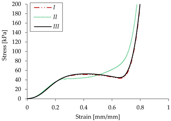
Figure 4.
Stress–strain response of dry 3D Spacer for low-speed compression tests.
2.3. Impact Tests
A drop tower test rig was used to evaluate the response of the imbibed material on impact [36]. The test rig (Figure 5) consists of a transparent vertical tube (1) supported by two rigid columns (3) fixed on a rigid base (2). Low energy impact is generated by an impactor, which falls guided by the transparent tube. No clamping mechanism is used to catch the impactor after impact.
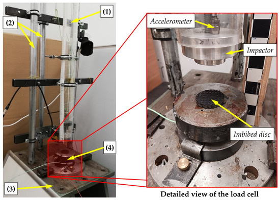
Figure 5.
Drop tower test rig: (1) transparent vertical tube, (2) rigid columns, (3) rigid base, (4) load cell.
Depending on the material used, the first impact is usually followed by a rebound. The acceleration of the impactor is recorded with an on-board wired accelerometer (KISTLER 8274A) (Kistler, Winterthur, Switzerland). The mass (up to 2 kg) of the impactor can be modified by replacing its constituent elements. The head of the impactor is cylindrical with a flat impact surface, and better guidance is achieved using a “tail” with a thin cylinder. The maximum impact velocity is 5 m/s corresponding to the maximum free fall height Zmax = 1.3 m. The samples are positioned on a piezoelectric load cell (4) (KISTLER 9051A, measuring ranges 0–12 kN/0–120 kN) preloaded between two heavy steel discs.
Each disc was carefully placed on the load cell to reduce solution loss and to assure the same imbibition level for all samples. During impact, the solution is squeezed radially outside the disc. Tests aiming to understand the solution’s flow contribution to the overall damping effect were performed with different impact speeds corresponding to two drop heights (Z1 = 350 mm and Z2 = 200 mm) and a dropping mass of 0.4 kg. The drop heights were chosen based on preliminary tests to ensure a strong response from the imbibed material, considering sample dimensions and avoiding compression beyond the densification limit (Figure 4).
Damping capacity was evaluated by measuring the transmitted force (via the force cell) and the impact force, calculated from the impactor’s acceleration during impact and its mass. The difference between the peaks of two forces gives an estimation of the damping effect generated by the compressed imbibed disc.
3. Results and Discussion
First, the variation in force over time was compared between the dry material (tests i, ii for Z1 = 350 mm and iii, iv for Z2 = 200 mm) and imbibed material with a solution of water and 9% PVA. Figure 6 presents force variation during tests using a drop height Z1 = 350 mm and Z1 = 200 mm. The tests presented for Z1 and Z2 are annotated with A and B, respectively. A minimum of three tests, each performed on a new sample, were performed to evaluate the reproducibility of the results. With a corresponding impact energy E1 = 1.38 J, the force recorded for dry material is significantly higher, 4 times greater. The dry material’s steep impact-force variation suggests that it was compressed enough to reach densification (“bottoming up” [37]). A force reduction was also observed for the imbibed material for Z2 = 200 mm, with a corresponding impact energy of E2 = 0.79 J.
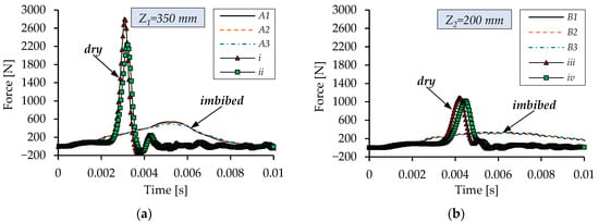
Figure 6.
Impact force–time variation for dry and imbibed 3D Spacer (water + 9% PVA) for two drop heights: (a) Z1 = 350 mm. (b) Z2 = 200 mm.
Figure 7 shows a magnified view in force variation (first 3 ms) for dry material, displaying typical behavior similar to the low-speed tests in Figure 4. The force has a linear variation, followed by a plateau. Furthermore, the force increases very steeply, marking the beginning of the densification stage. For this test, the stress corresponding to the maximum force produced divided by area is 2.2 MPa. Comparing this result with the response of dry material (Figure 6) and other studies from the literature [33], the impact energy was too high for this drop height causing a hard contact due to “bottoming up”.
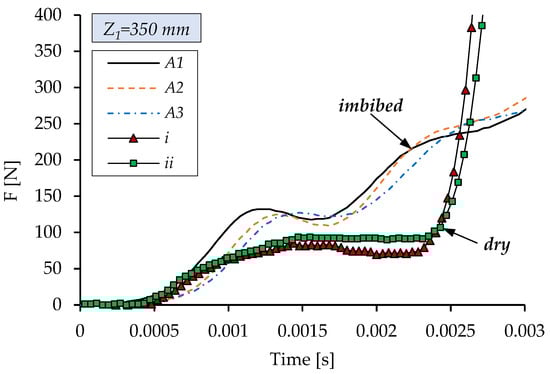
Figure 7.
Zoom on 0–0.003 s, showing transmitted force variation during impact for dry and imbibed 3D Spacer (with PVA-S).
The experimental data shows a 4% scattering in terms of maximum force. This is due to errors in drop height adjustment, small kinetic energy losses from friction between the impactor and guiding tube or misalignment of the contact surfaces. All these factors can lead to unequal distribution of contact pressure. The misalignment of the contact surfaces, observed using high-speed images, is up to a maximum of 1.5°. With higher impact energies, misalignment effects become more significant, causing hard contact between the falling body and the steel base steel disc.
The values of the maximum force with respect to each CNF-OH nanofiller concentration are presented in Figure 8 in average form (for 3 tests) with standard deviation included. The average standard deviation calculated for maximum force is less than 5 N for Z1 = 350 mm and less than 8 N for Z2 = 200 mm. The results presented in this figure show a 15% reduction for 0.1% CNF-OH nanofiller concentration for Z1= 350 mm and a 7% reduction at Z2= 200 mm, compared to the force generated when using the base solution. Better performance was observed for Z2= 200 mm drop height when using 0.2% CNF-OH nanofiller concentration with an important reduction of 14%. Based on these results the optimal nanofiller concentration for maximum damping effect is around 0.1%.
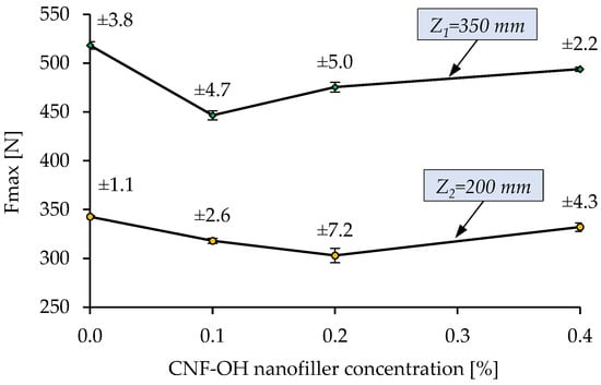
Figure 8.
Average maximum impact force recorded for all PVA-S for two drop heights.
At low to moderate CNF-OH concentrations (0.1–0.2%), the polymer network remains sufficiently open to allow internal flow during impact, enabling effective viscous dissipation. At high shear rates, hydrogen bonds between PVA chains and CNF-OH partially break, reducing viscosity and facilitating energy absorption. However, at higher concentrations (>0.2%), excessive nanofiber entanglement and dense hydrogen-bonded networks create a quasi-gel structure with very high zero-shear viscosity. This restricts fluid mobility within the porous textile, leading to premature densification and reduced damping efficiency despite stronger low-shear resistance. Thus, optimal performance occurs at intermediate concentrations where shear-thinning is maximized without sacrificing flowability.
The acceleration during impact was also recorded for the dropping body using the sensor mounted on top. From Figure 9, which depicts the acceleration variation during impact, one can observe a considerable attenuation when the material is imbibed, relative to tests performed on dry porous material in apparently identical conditions (test i, ii,… iv).
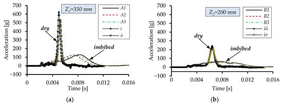
Figure 9.
Impactor acceleration variation during impact on dry and imbibed (PVA-S) 3D Spacer sample for different drop heights: (a) Z1 = 350 mm. (b) Z2 = 200 mm.
Figure 10 illustrates the acceleration variation for tests with different nanofiller concentrations. The comparison reveals minor differences, as expected given that acceleration measured on the falling body reflects only post-contact displacement.
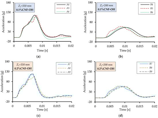
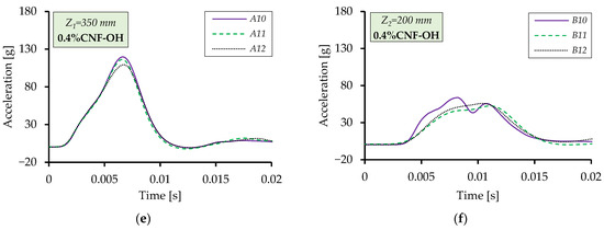
Figure 10.
Impactor acceleration variation during impact on imbibed 3D Spacer (PVA-S CNF-OH): (a) Z1 = 350 mm: A4, A5, A6 → 0.1%. (b) Z2 = 200 mm: B4, B5, B6 → 0.1%. (c) Z1 = 350 mm: A7, A8, A9 → 0.2%. (d) Z2 = 200 mm: B7, B8, B9 → 0.2%. (e) Z1 = 350 mm: A10, A11, A12 → 0.4%. (f) Z2 = 200 mm: B10, B11, B12 → 0.4%.
Figure 11 shows representative results for two tests at drop heights of Z1 = 350 mm and Z2 = 200 mm. After accounting for the ≈0.2 ms data-acquisition delay, the impact and transmitted forces were almost identical, with a small difference near the peak indicating the existence of the damping mechanism. This discrepancy arises mainly from the accelerometer accuracy and the slight tilting of the impactor. These observations confirm the reliability of the force-transducer and accelerometer data. By integrating the acceleration-time signal using Equations (1) and (2), the impactor’s velocity v and material deformation h during compression be obtained. Then, using the initial thickness h0 of the imbibed sample strain, ε can also be calculated (Equation (3)).
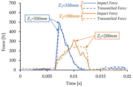
Figure 11.
Comparison between impact and transmitted force for imbibed 3D Spacer (water + 9% APV + 0.4 CNF-OH) from Z1 = 350 mm and Z2 = 200 mm, with an impactor of 0.402 kg.
For the displacement calculation, the contact point is defined at the initial thickness h0 of the imbibed disk. The impactor descends until the maximum force is reached (Figure 11) and its velocity falls to zero, after which it rebounds as the velocity increases and the force decreases.
Figure 12a shows the influence of the nanofiller concentration on dynamic stress for Z1 = 350 mm. At 0.1% and 0.2% nanofiller concentrations, the stress is initially high but drops markedly at large strains compared to the other concentrations. We attribute this to the lower viscosity at high strain, which facilitates fluid flow during compression and enhances impact damping when void volume is low. Based on Figure 4, the material “solidification” begins a strain of around 0.6–0.7. The curves are limited to 0.95 strain, before the theoretical limit of 1 when there are no voids. Similar trends appear in Figure 12b for Z2 = 200 mm, where stresses at low strain are also reduced for the 0.1% and 0.2% nanofiller concentrations. Some inconsistencies arose when integrating acceleration to determine cell deformation during impact, but the errors were quantified and corrected. Some deviations result from slight axial deformation of the loading cell.
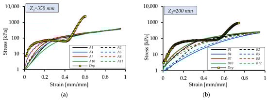
Figure 12.
Stress vs. strain variation for the imbibed 3D Spacer with PVA-S CNF-OH: (a) Z1 = 350 mm: A1, A2 → PVA-S, A4, A5 → 0.1%, A7, A8 → 0.2%, A10, A11 → 0.4%, (b) Z2 = 200 mm: B1,B2 → PVA-S, B4, B5 → 0.1%, B7, B8 → 0.2%, B10, B11 → 0.4%.
The stress–strain curve provides insight into damping behavior, but its full value emerges when the area under the curve is integrated to determine the absorbed energy per unit volume E (Equation (4)). An effective impact-damping material should absorb as much energy as possible while minimizing the force transmitted to the protected object. To further assess performance, the efficiency Eff (Equation (5)) can be used, which is calculated from the absorbed energy [33]:
Figure 13 shows the specific energy absorption for the base solution and the different nanofiller concentrations, while Figure 14 presents the corresponding efficiencies. Absorbed energy increases steadily with stress, and in tests where the stress reaches a plateau, a more pronounced rise is observed. Compared with the dry sample, the behavior is fundamentally different. For the dry material, absorbed energy and efficiency rise sharply when stress remains nearly constant in the plateau region (Figure 12). Once the stress begins to increase again, absorbed energy levels off and efficiency drops, indicating the onset of densification.
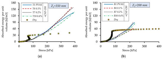
Figure 13.
Absorbed energy per unit volume for different drop heights: (a) Z1 = 350 mm, (b) Z2 = 200 mm.
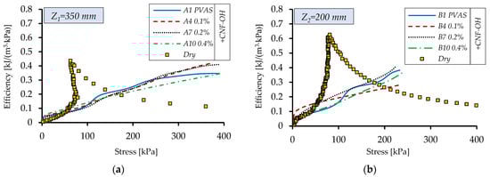
Figure 14.
Efficiency diagram for different drop heights: (a) Z1 = 350 mm, (b) Z2 = 200 mm.
In contrast, the presence of the fluid in between the fibers maintains a continuous increase in efficiency despite the reduction in the pore volume. This highlights the ability of the shear-thinning fluid to keep flowing through closing pores with high shear. As the pore volume rapidly decreases, the imbibed fluid is forced through progressively narrower inter-fiber channels, resulting in high shear rates and flow resistance. The response therefore depends strongly on how viscosity varies with shear rate. For shear-thinning fluids such as the PVA–CNF solution, effective viscosity decreases as shear rate increases, enabling sustained fluid flow even as pores close. This radial flow allows viscous dissipation to persist throughout compression and delays the stiffening of the structure. Consequently, the imbibed textile exhibits sustained damping behavior, reduced peak forces and a steadily increasing energy-absorption efficiency at high strains.
Shear-thickening fluids behave oppositely: their viscosity increases sharply with shear rate, causing rapid pressure generation in narrowing pores. This leads to early stiffening and shifts dissipation from viscous flow to fiber-to-fiber friction. Because flow is hindered rather than supported, shear-thickening fluids cannot maintain continuous radial displacement and are therefore poorly suited for highly compressible porous architectures such as 3D spacer textiles.
To better understand the response of the imbibed material, some of the XPHD assumptions are considered valid [7]: the porous material is homogeneous and isotropic at macroscale, the fluid flow is isothermal, the fluid pressure is considered constant across the thickness of the material (the material is relative thin) and the area of the porous disk is preserved during compaction (the conservation of the solid matrix). The presence of porous structure amplifies the hydrodynamic pressure generated by resistive flow through pores and allows high compressions (orders of millimeters). The force attenuation mechanism is directly influenced by the permeability of the porous material, which depends on porosity and the properties of the imbibed fluid. When the soft (highly compressible) materials are subjected to compression, their porosity decreases, and correspondingly, the permeability reduces as well. In general, the resistance to squeeze increases sharply, generating a progressive stiffness.
A fundamental concept for energy damping based on which shear-thinning fluids flow through deformable porous structure presents good potential. When the size of the pore is reduced, the shear rate will increase with flow velocity, and the specific reduction in viscosity will encourage the radial displacement of fluid. In simpler terms, for the shear-thinning fluid the flow will accelerate easily through the contracting pores, sustaining an even more pronounced damping process.
At high impact velocities, flow speed can be high enough for inertial effects to be comparable with viscous effects. A thorough analysis of these effects can be carried out using Darcy’s law modification proposed by Forchheimer (for inertial effects specific to high flow speeds). A pore-based Reynolds number (Rep) can be used dependent on the average flow velocity (um), dynamic viscosity, density (ρ) of the fluid and a characteristic dimension of the porous material. Many studies try to find the values of the Rep number when the Darcy flow regime ends and indicate that flow enters a transition regime for values between 1 and 10 [38,39]. Depending on the type of the material, the characteristic dimension can be defined using the grain/fiber/sphere mean diameter, permeability or porosity. In this study permeability-based Reynolds was preferred, as in Cicone et al. [13] and Lupu et al. [35]:
where ϕ is the permeability of the yarn and η is the fluid viscosity.
The Reynolds number (Re) can be approximated using the theoretical analysis conducted by Cicone et al. [13], which includes a validation with impact experiments on the same textile material. Considering the experimental conditions used and assuming Newtonian fluid, it was found that Re < 2.
High-speed filming was carried out using a Photron FASTCAM SA-Z camera (Photron, San Diego, CA, USA) to better understand the interaction between the shear-thinning fluid and 3D textile during impact. Direct observation of the fluid–structure interaction inside the porous network was not possible as radial flow prevents clear visualization of the interior during compression. However, the images reveal interfacial instabilities characteristic to immiscible flow between a non-Newtonian fluid and gases when the fluid is squeezed out during compression [14]. Radial displacement of the fluid withing the porous media produces “fingering” instabilities, ejecting the fluid as small jets into the surrounding air. Partial imbibition at the top surface of the sample can trap air beneath the impactor, further contributing to these instabilities as the fluid is expelled out.
High-speed footage of the dry 3D textile under compression provided insight into how the internal structure deforms (Figure 15). The structure of the 3D textile is complex, with 3D monofilament shapes that are difficult to quantify or model. The images revealed that during compression, the monofilaments bend, collapse and interact with the outer layers, while the contact points to outer layer remain relatively fixed. Comparison of selected frames indicates that flow between vertical filaments dominates at the start of compression, whereas at later stages the outer layers play an increasingly important role. Their porosity—and thus their permeability—becomes a key parameter governing the compression response.
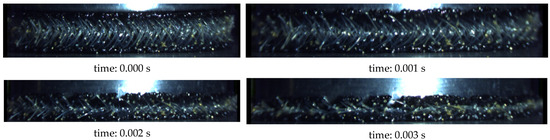
Figure 15.
Deformation of the internal structure during impact compression during successive moments.
4. Conclusions
The dynamic compression response of three-dimensional textiles imbibed with shear-thinning fluids (water-based polymer solutions) was experimentally studied. The measured impact force for the imbibed sample showed an important reduction compared to the dry material. Further addition of nanofiller increased the performance of the solution, and an optimal concentration was revealed based on the experimental results. The relatively low concentration of nanofiller 0.1–0.2% showed the best results for two different drop heights. A higher threshold shear stress for the fluid and a more accentuated drop in viscosity with shear rate showed a better damping effect. Partially imbibed discs were used because achieving complete imbibition of the material was challenging.
The 3D textiles, imbibed with shear-thinning, could reduce impact force at medium impact speeds (<10 m/s). The present results, which show reduced transmitted forces and enhanced damping performance, elucidate the behavior of shear-thinning fluids in deformable porous media. Energy absorption was also evaluated and is based mainly on viscous flow and solid structure compression. Observations using experimental results confirm that shear-dependent viscosity plays a central role in sustaining flow through closing pores and in enabling effective impact-energy dissipation in shear-thinning-imbibed 3D textiles. At higher impact velocities, scaling the proposed mechanism becomes challenging due to the combined effects of rapid pore collapse, permeability reduction, material stiffness and fluid inertia.
Author Contributions
Conceptualization, P.T.; methodology, P.T.; software, P.T.; validation, P.T., I.-R.N. and T.C.; formal analysis, P.T. and T.C.; investigation, P.T., I.-R.N. and A.D.; resources, P.T., A.D. and E.R.; data curation, P.T.; writing—original draft preparation, P.T. and I.-R.N.; writing—review and editing, I.-R.N.; visualization, P.T. and I.-R.N.; supervision, T.C.; project administration, P.T.; funding acquisition, P.T. and T.C. All authors have read and agreed to the published version of the manuscript.
Funding
This research was partially supported by the Romanian Ministry of Education and Research, CNCS—UEFISCDI through projects PN-IV-P7-7.1-PED-2024-1307 and PN-III-P1-1.1-PD-2019-1228.
Institutional Review Board Statement
Not applicable.
Informed Consent Statement
Not applicable.
Data Availability Statement
The raw data supporting the conclusions of this article will be made available by the authors on request.
Acknowledgments
Aurel Diacon and Edina Rusen are thankful for the financial support provided by the Executive Agency for Higher Education, Research, Development, and Innovation Funding (UEFISCDI), the Ministry of Education of Romania, through the National Projects PN IV P7-7.1-PTE-2024-0486 ctr. no. 1PTE/2025.
Conflicts of Interest
The authors declare no conflicts of interest.
Abbreviations
The following abbreviations are used in this manuscript:
| XPHD | ex-poro-hydrodynamic |
| 3D | three-dimensional |
References
- Dawson, M.A.; Germaine, J.T.; Gibson, L.J. Permeability of open-cell foams under compressive strain. Int. J. Solids Struct. 2007, 44, 5133–5145. [Google Scholar] [CrossRef]
- Gibson, I.J.; Ashby, M.F. The mechanics of three-dimensional cellular materials. Proc. R. Soc. Lond. A Math. Phys. Sci. 1982, 382, 43–59. [Google Scholar] [CrossRef]
- Guo, H.; Liu, Y.; Xia, Y.; Hu, H.; Wang, Y.; Qiu, G. Compressive mechanics of warp-knitted spacer fabrics. J. Ind. Text. 2021, 51, 611–631. [Google Scholar] [CrossRef]
- Rehkopf, J.D.; Brodland, G.W.; McNeice, G.M. Experimentally separating fluid and matrix contributions to polymeric foam behavior. Exp. Mech. 1996, 36, 1–6. [Google Scholar] [CrossRef]
- Mills, N.J.; Lyn, G. Modelling of Air Flow in Impacted Polyurethane Foam. Cell. Polym. 2002, 21, 343–368. [Google Scholar] [CrossRef]
- Dawson, M.A.; McKinley, G.H.; Gibson, L.J. The Dynamic Compressive Response of Open-Cell Foam Impregnated With a Newtonian Fluid. J. Appl. Mech. 2008, 75, 041015. [Google Scholar] [CrossRef]
- Pascovici, M.D.; Cicone, T. Squeeze-film of unconformal, compliant and layered contacts. Tribol. Int. 2003, 36, 791–799. [Google Scholar] [CrossRef]
- Feng, J.; Weinbaum, S. Lubrication theory in highly compressible porous media: The mechanics of skiing, from red cells to humans. J. Fluid Mech. 2000, 422, 281–317. [Google Scholar] [CrossRef]
- Turtoi, P.; Lupu, G.; Cicone, T.; Apostol, D. Experimental investigation of the limits of fluid squeeze out from an imbibed porous material. IOP Conf. Ser. Mater. Sci. Eng. 2020, 997, 012019. [Google Scholar] [CrossRef]
- Kunik, S.; Fatu, A.; Bouyer, J.; Doumalin, P. Experimental and numerical study of self-sustaining fluid films generated in highly compressible porous layers imbibed with liquids. Tribol. Int. 2020, 151, 106435. [Google Scholar] [CrossRef]
- Pascovici, M.D.; Popescu, C.S.; Marian, V.G. Impact of a rigid sphere on a highly compressible porous layer imbibed with a Newtonian liquid. Proc. IME J. J. Eng. Tribol. 2010, 224, 789–795. [Google Scholar] [CrossRef]
- Hilyard, N.C.; Djiauw, L.K. Observations on the Impact Behaviour of Polyurethane Foams; I. The Polymer Matrix. J. Cell. Plast. 1971, 7, 33–42. [Google Scholar] [CrossRef]
- Cicone, T.; Pascovici, M.D.; Melciu, C.; Turtoi, P. Optimal porosity for impact squeeze of soft layers imbibed with liquids. Tribol. Int. 2019, 138, 140–149. [Google Scholar] [CrossRef]
- Lee, Y.H.; Azaiez, J.; Gates, I.D. Interfacial instabilities of immiscible non-Newtonian radial displacements in porous media. Phys. Fluids 2019, 31, 043103. [Google Scholar] [CrossRef]
- Götz, T.; Parhusip, H.A. On an asymptotic expansion for Carreau fluids in porous media. J. Eng. Math. 2005, 51, 351–365. [Google Scholar] [CrossRef]
- Ortega, J.M. A porous media model for blood flow within reticulated foam. Chem. Eng. Sci. 2013, 99, 59–66. [Google Scholar] [CrossRef] [PubMed]
- Dawson, M.A.; McKinley, G.H.; Gibson, L.J. The Dynamic Compressive Response of an Open-Cell Foam Impregnated With a Non-Newtonian Fluid. J. Appl. Mech. 2009, 76, 061011. [Google Scholar] [CrossRef]
- Suciu, C.V.; Fukui, S.; Kimura, Y. Modeling and Simulation of a Shock Absorbing Shell for Ballistic Vests and Helmets to Achieve Optimal Protection. In Proceedings of the 2011 International Conference on P2P, Parallel, Grid, Cloud and Internet Computing, Barcelona, Spain, 26 October 2011; IEEE Computer Society: Washington, DC, USA, 2011; pp. 390–395. [Google Scholar]
- Gürgen, S.; Kuşhan, M.C.; Li, W. Shear thickening fluids in protective applications: A review. Prog. Polym. Sci. 2017, 75, 48–72. [Google Scholar] [CrossRef]
- Zielinska, D.; Delczyk-Olejniczak, B.; Wierzbicki, L.; Wilbik-Hałgas, B.ż.e.; Struszczyk, M.H.; Leonowicz, M. Investigation of the effect of para-aramid fabric impregnation with shear thickening fluid on quasi-static stab resistance. Text. Res. J. 2014, 84, 1569–1577. [Google Scholar] [CrossRef]
- Balali, E.; Kordani, N.; Sadough Vanini, A. Response of glass fiber-reinforced hybrid shear thickening fluid (STF) under low-velocity impact. J. Text. Inst. 2017, 108, 376–384. [Google Scholar] [CrossRef]
- Fahool, M.; Sabet, A.R. Parametric study of energy absorption mechanism in Twaron fabric impregnated with a shear thickening fluid. Int. J. Impact Eng. 2016, 90, 61–71. [Google Scholar] [CrossRef]
- Sun, L.-L.; Xiong, D.-S.; Xu, C.-Y. Application of shear thickening fluid in ultra high molecular weight polyethylene fabric. J. Appl. Polym. Sci. 2013, 129, 1922–1928. [Google Scholar] [CrossRef]
- Srivastava, A.; Majumdar, A.; Butola, B.S. Improving the Impact Resistance of Textile Structures by using Shear Thickening Fluids: A Review. Crit. Rev. Solid State Mater. Sci. 2012, 37, 115–129. [Google Scholar] [CrossRef]
- Bremner, N. Spacers about to take off? Knitt. Int. 2004, 111, 40–41. [Google Scholar]
- Bruer, S.M.; Powell, N.; Smith, G. Three-dimensionally knit spacer fabrics: A review of production techniques and applications. J. Text. Appar. Technol. Manag. 2005, 4, 1–31. [Google Scholar]
- Rebelo, S.L.H.; Guedes, A.; Szefczyk, M.E.; Pereira, A.M.; Araújo, J.P.; Freire, C. Progress in the Raman spectra analysis of covalently functionalized multiwalled carbon nanotubes: Unraveling disorder in graphitic materials. Phys. Chem. Chem. Phys. 2016, 18, 12784–12796. [Google Scholar] [CrossRef]
- Li, J.; Yang, M.; Zhao, Y.; Zhang, W.; Huo, L.; Zhang, X.; Gao, J.; Pang, H.; Xue, H. Flexible All-Solid-State Supercapacitor Fabricated with Nitrogen-Doped Carbon Nanofiber Electrode Material Derived from Polyacrylonitrile Copolymer. ACS Appl. Energy Mater. 2021, 4, 5830–5839. [Google Scholar] [CrossRef]
- Maeda, H.; Kawai, T.; Sekii, S. Intra- and intermolecular hydrogen bonds in polyvinyl alcohol solutions. J. Polym. Sci. 1959, 35, 288–292. [Google Scholar] [CrossRef]
- Briscoe, B.; Luckham, P.; Zhu, S. The effects of hydrogen bonding upon the viscosity of aqueous poly(vinyl alcohol) solutions. Polymer 2000, 41, 3851–3860. [Google Scholar] [CrossRef]
- Hagiopol, C.; Georgescu, M.; Deleanu, T.; Dimonie, V. Rheological behaviour of aqueous solutions of polyvinylalcohol in the presence of some nonionic substances. Colloid Polym. Sci. 1979, 257, 1196–1202. [Google Scholar] [CrossRef]
- Gao, H.-W.; Yang, R.-J.; He, J.-Y.; Yang, L. Rheological behaviors of PVA/H2O solutions of high-polymer concentration. J. Appl. Polym. Sci. 2010, 116, 1459–1466. [Google Scholar] [CrossRef]
- Liu, Y.; Hu, H.; Zhao, L.; Long, H. Compression behavior of warp-knitted spacer fabrics for cushioning applications. Text. Res. J. 2012, 82, 11–20. [Google Scholar] [CrossRef]
- Lupu, G.C.; Fătu, A.; Henry, Y.; Turtoi, P.; Cicone, T. Mechanical and structural characterisation of a 3D warp-knitted spacer fabric subjected to compression. IOP Conf. Ser. Mater. Sci. Eng. 2022, 1262, 012024. [Google Scholar] [CrossRef]
- Lupu, G.-C.; Fatu, A.; Cicone, T.; Enescu, C.; Marinescu, A. Compression behavior and in-plane permeability of 3D textiles via FEM and CFD simulation. Text. Res. J. 2025. accepted. [Google Scholar] [CrossRef]
- Nechita, I.R.; Turtoi, P.; Cicone, T.; Puică, C. Instrumentation and preliminary evaluation of a drop tower tester for low and medium impact energy. IOP Conf. Ser. Mater. Sci. Eng. 2022, 1262, 012027. [Google Scholar] [CrossRef]
- Parisi, M.; Allen, T.; Colonna, M.; Pugno, N.; Duncan, O. Indentation and impact response of conventional, auxetic, and shear thickening gel infused auxetic closed cell foam. Smart Mater. Struct. 2023, 32, 074004. [Google Scholar] [CrossRef]
- Bear, J. Dynamics of Fluids in Porous Media; Elsevier: New York, NY, USA, 1972. [Google Scholar]
- Dybbs, A.; Edwards, R.V. A new look at porous media fluid mechanics—Darcy to turbulent. In Fundamentals of Transport Phenomena in Porous Media; Bear, J., Corapcioglu, M.Y., Eds.; Springer: Dordrecht, The Netherlands, 1984; Volume 82, pp. 199–256. [Google Scholar] [CrossRef]
Disclaimer/Publisher’s Note: The statements, opinions and data contained in all publications are solely those of the individual author(s) and contributor(s) and not of MDPI and/or the editor(s). MDPI and/or the editor(s) disclaim responsibility for any injury to people or property resulting from any ideas, methods, instructions or products referred to in the content. |
© 2026 by the authors. Licensee MDPI, Basel, Switzerland. This article is an open access article distributed under the terms and conditions of the Creative Commons Attribution (CC BY) license.