Abstract
This study experimentally evaluates the structural performance of Concrete-Filled Double-Skin (CFDS) hybrid connections that are intended as key components of large-scale floating offshore wind substructures. The innovative aspect of this work lies in the direct experimental comparison of five representative connection details—Headed Stud (HS), Perfobond (PB), L-beam-joint (LJ), L-beam-spacing (LS), and Angle (AN)—with respect to multiple performance indices that are critical under harsh offshore environments. First, full-scale CFDS specimens were fabricated with identical global dimensions while varying only the connection details. The hybrid behavior of the CFDS system arises from the complementary actions of the outer steel tube, which primarily resists tensile forces, and the infilled concrete, which provides dominant compressive resistance and confinement. This composite interaction enhances the stiffness, ductility, and energy absorption capacity of the member under flexural demands, which are essential for floating offshore structures operating under complex marine loading. Second, monotonic bending tests were conducted using a 2000 kN actuator under a cantilever-type configuration, and load–displacement responses were recorded at three locations. Third, the stiffness, ductility, and energy absorption capacity (toughness) were quantified from the measured curves to clarify the deformation and failure characteristics of each connection type. The results show that the PB connection achieved the highest maximum load and exhibited stable ductile behavior with plastic energy dominating the total toughness. The LJ connection provided well-balanced stiffness and deformation capacity with low sensitivity to measurement locations, indicating high reliability for design applications. In contrast, the HS and LS connections experienced localized slip and position-dependent stiffness, while the AN connection showed the lowest load-carrying efficiency. Overall, the findings highlight that connection-level detailing has a decisive influence on the global performance of CFDS hybrid members and provide fundamental data for developing design guidelines for floating offshore structures operating under complex marine loading conditions.
1. Introduction
With the global acceleration of carbon neutrality initiatives and energy transition policies, offshore wind power has emerged as a key pillar of the future energy industry. Offshore wind energy can achieve high power generation efficiency by utilizing abundant marine wind resources, while offering advantages such as reduced land use, noise, and environmental constraints compared to onshore installations. However, conventional fixed-bottom offshore wind turbines are limited to installation depths of less than 50 m, facing several technical challenges, including the lack of suitable sites, complex offshore construction processes, and difficulties in ensuring foundation stability. In contrast, floating offshore wind turbines (FOWTs) can be installed in deep waters and harness high wind speeds in far-offshore environments, thereby attracting attention as a core technology for the large-scale deployment of renewable energy infrastructure [1,2,3,4].
Nevertheless, the substructures of FOWTs are continuously exposed to extreme marine environmental loads such as waves, currents, and wind. Ensuring long-term structural reliability and durability cannot be achieved through conventional design approaches alone. Steel-only structures are susceptible to corrosion and fatigue damage, while concrete-only structures suffer from excessive self-weight and reduced performance under cyclic loading due to their brittle behavior [5,6]. To overcome these limitations, hybrid floating substructures that combine the material advantages of steel and concrete have recently gained attention as promising alternatives [7,8,9].
Among these, the CFDS (Concrete-Filled Double-Skin Steel) or CFDST (Concrete-Filled Double-Skin Steel Tube) system is a composite structure in which concrete is filled between inner and outer steel tubes (or plates), allowing simultaneous utilization of the tensile resistance of steel and the compressive resistance of concrete [10,11,12,13]. The CFDS system therefore exhibits behavior analogous to that of composite materials, in which the concrete core functions as the matrix and the steel plates act as the reinforcement. The concrete provides compressive resistance and contributes to confinement, while the steel plates primarily resist tensile forces and enhance shear-transfer performance along the interface. Recent studies have examined the material behavior of marine-grade structural steels such as AH36, showing predictable mechanical degradation and corrosion characteristics under long-term seawater exposure and welded conditions [14,15], as well as improved durability when cathodic protection or calcareous deposits are applied [16]. Additionally, the mechanical properties and durability of normal-strength concrete in marine environments—including chloride ingress, microstructural deterioration, and long-term strength evolution—have been comprehensively reviewed in the recent literature [17,18], supporting the relevance of the selected materials for offshore composite systems. This reinforcing–matrix interaction leads to improved stiffness, ductility, and energy absorption capacity under bending, representing a key composite action that governs the structural behavior of CFDS members. Extensive research (both experimental and numerical) has investigated the mechanical and compressive behaviors of such systems, demonstrating their superior load-carrying capacity, confinement efficiency, and ductility under various loading conditions. While prior studies have clarified fundamental mechanical characteristics, the connection behavior of CFDS structures under complex loading conditions remains insufficiently understood [10,11,12,13,19,20,21,22,23]. This structural system exhibits high stiffness, energy absorption capacity, impact resistance, and fatigue resistance, while also offering superior corrosion and seawater erosion resistance due to the steel confinement effect [24,25,26]. In addition, CFDS structures provide advantages in fabrication efficiency and cost-effectiveness compared to conventional steel structures, and extensive research is underway to apply them to large-scale floating substructure development [27,28,29].
In particular, the connection details of CFDS-based substructures play a critical role in determining the load transfer performance and fatigue life of the overall structure. These connections distribute loads transferred from the upper tower and platform and control deformation and energy dissipation under cyclic loading. To clarify the structural context in which CFDS hybrid members are applied, Figure 1 illustrates the global configuration of a floating offshore wind turbine and the locations where CFDS columns are employed as primary load-carrying components. The figure also presents the detailed interface between the steel plates and the CFDS member, showing where the connection details investigated in this study are installed. This schematic highlights the load-transfer mechanism from the tower to the buoyant substructure and demonstrates why the performance of CFDS connection details under bending is critical for floating offshore applications. Accordingly, various connection methods have been proposed, with the Headed Stud (commonly used in hybrid member joints) serving as a representative reference, alongside the Perfobond type [11,12,13,24,25,26,27,28,29,30,31,32,33,34]. The Perfobond rib provides high shear stiffness and superior ultimate load capacity but has a relatively complex fabrication process [11,12,13,24,25], whereas the Headed Stud offers simple installation and predictable behavior under cyclic loading [29,30,31]. In addition, L-beam and Angle-type connections have advantages in manufacturability and cost-efficiency, though reinforcement is required to prevent local buckling or slip behavior [32,33,34].
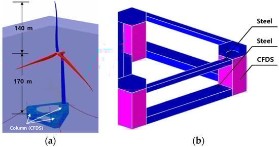
Figure 1.
Structural context of CFDS hybrid members in floating offshore wind platforms. (a) Global configuration of a floating offshore wind turbine, showing the tower height, platform draft, and locations of CFDS columns; (b) Schematic illustration of the CFDS–steel interface, highlighting the composite interaction and the region where connection details are installed.
Previous studies have primarily focused on static or low-cycle fatigue behavior of CFDS members or the performance evaluation of individual connection types [8,9,10,27,28,29]. However, experimental comparative studies considering combined loading conditions (static, cyclic, and impact loads) on floating substructure connections remain very limited. Recent advances in floating offshore substructures have increasingly adopted hybrid composite systems to improve stiffness, durability, and long-term stability under harsh marine environments. For example, ref. [35] proposed an innovative FRP-reinforced UHPC floating wind turbine foundation and demonstrated that hybridized composite members can significantly enhance structural efficiency under combined environmental loads. In parallel, Mo et al. [36] investigated hybrid FRP–concrete–steel double-skin tubular beams incorporating PBL shear connectors and reported substantial improvements in flexural stiffness and shear transfer capacity. These studies highlight the growing research interest in connector-level behavior within hybrid composite members and reinforce the need to evaluate CFDS connection performance under bending for floating offshore structural applications. Moreover, few studies have comprehensively evaluated local stress concentration, fatigue damage, and slip behavior under realistic marine environmental conditions [37,38]. Design guidelines and performance evaluation frameworks for CFDS connections that simultaneously consider fatigue, impact, and corrosion conditions are yet to be fully established [37,38].
However, despite extensive studies on the mechanical behavior of CFDS and CFDST members, most prior research has focused on global structural responses such as axial compression, flexural resistance, cyclic behavior, and corrosion–fatigue effects. The behavior of connection details—which governs load transfer between hybrid components—has received comparatively little attention. In particular, no comprehensive experimental comparison has been conducted on different connector types under bending, even though bending-induced load transfer is a critical mechanism for floating offshore substructures. Furthermore, the connection performance of CFDS members has rarely been evaluated in the context of floating platforms, where components experience complex environmental loading and repeated deformation. Therefore, a clear research gap exists in understanding the relative performance of various CFDS connection configurations under bending. This study addresses this gap by experimentally evaluating five representative connection types and analyzing their stiffness, ductility, and energy absorption characteristics relevant to floating offshore structural applications.
Therefore, this study experimentally investigates five types of connection details (Headed Stud, Perfobond, L-beam-joint, L-beam-spacing, and Angle) for CFDS-based large-scale hybrid floating offshore wind substructures. For each specimen, load–displacement behavior, stiffness, ductility, and energy absorption capacity were quantitatively analyzed. Based on the experimental results, the differences in structural performance according to connection type and design parameters were identified, and optimal design directions were proposed to improve the structural reliability and cost-efficiency of floating substructures. The findings of this study are expected to serve as fundamental data for establishing design standards and performance evaluation frameworks for CFDS-based hybrid floating structures operating in extreme marine environments.
To address the remaining knowledge gaps regarding the connection-level behavior of CFDS hybrid members, the present study aims to clarify the structural performance of five representative connection details under bending and to elucidate the associated deformation and failure mechanisms. These research objectives establish the basis for the comparative evaluation presented in the subsequent sections and are revisited in the Conclusions.
The CFDS members in this study were constructed using structural steel with a yield strength of approximately 355 MPa and 35 MPa normal-strength concrete. The concrete used in this study was supplied by a certified ready-mixed concrete manufacturer with a specified design strength of 35 MPa, and the strength level was verified through the manufacturer’s quality assurance documentation. The 35 MPa concrete used in this study was prepared with both fine and coarse aggregates following standard structural concrete mix proportions, ensuring adequate workability and uniform mechanical properties during casting. The steel plates have a typical density of about 7850 kg/m3, while the infilled concrete exhibits a density of approximately 2350 kg/m3. The mechanical characteristics of these materials—particularly the tensile resistance of the steel and the compressive and confinement behavior of the concrete—play a significant role in governing the stiffness, deformation capacity, and composite action of the CFDS system. These properties are therefore referenced throughout the discussion of the experimental results to clarify their structural influence.
In selecting the five connector types, the design concept was to represent the fundamental shear-transfer and confinement mechanisms that govern composite action in CFDS members. The Headed Stud (HS) represents bearing-type shear transfer, the Perfobond (PB) generates dowel action through perforations, the L-beam-joint (LJ) and L-beam-spacing (LS) provide rigid frame-type confinement, and the Angle (AN) represents local bearing-type interaction. These mechanisms collectively cover the performance spectrum required for floating offshore structures, including initial stiffness, ductility, and stable shear transfer under repeated bending.
The main design approach of this study was to maintain identical global dimensions and material properties for all CFDS specimens so that the connector type becomes the sole experimental variable. This enables the direct evaluation of how each connection concept influences stiffness, ductility, and energy absorption capacity under bending, which are critical for floating offshore structures.
2. Variable Definition and Experimental Plan
2.1. Determination of Experimental Variables
In this study, the connection details of hybrid members (which are regarded as the core components of CFDS structures) were selected as the primary research focus. The performance evaluation was expanded beyond the conventional analysis of maximum load and displacement behavior to include toughness (energy absorption), ductility, and stiffness as key performance indicators.
The energy absorption capacity (toughness) was quantified as the area under the load–displacement curve, which serves as an indicator of structural resistance against impact and cyclic loading. Ductility was evaluated as the ratio of the ultimate displacement to the yield displacement, aiming to assess the deformation capacity of the structure. Stiffness was evaluated from the slope of the load–displacement curve between 20% and 80% of the maximum load, as detailed in Section 4.4, to assess the structural behavior and the efficiency of load transfer.
The connection types were determined based on conventional hybrid member joints, with the Headed Stud (HS) used as the reference type. The Headed Stud connection offers simple fabrication and efficient shear transfer, making it a widely adopted detail for hybrid members; however, it tends to be vulnerable to tensile and local failures. To overcome these limitations, four additional connection types were considered: Perfobond (PB), L-beam-joint (LJ), L-beam-spacing (LS), and Angle (AN) connections. Accordingly, a total of five connection configurations were established as the main experimental variables.
To ensure a fair comparison, all specimens shared identical global dimensions and material properties, allowing the connection configuration to serve as the sole experimental variable.
2.2. Overview of Test Specimens and Connection Layout
All specimens were designed with identical geometric dimensions (width 500 mm × thickness 450 mm × height 800 mm) to isolate the influence of connection details as the sole experimental variable. As the specimens were based on the CFDS structural system, 10 mm-thick steel plates were positioned on both outer faces, and connection components were installed on these plates. The 430 mm internal section between the plates was filled with 35 MPa-grade concrete to simulate the composite behavior of the CFDS configuration. The detailed configuration of the specimens is illustrated in Figure 2. To improve reproducibility, Table 1 summarizes all dimensional details for each connection type, including connector sizes, number of units, spacing, and layout configurations.
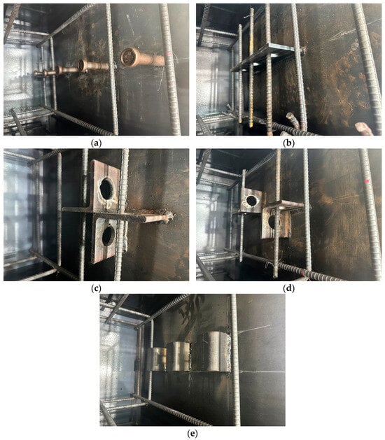
Figure 2.
Shapes and details of connection specimens. (a) Headed stud (HS); (b) Perfobond (PB); (c) L-beam-joint (LJ); (d) L-beam-spacing (LS); (e) Angle (AN).

Table 1.
Detail of Connections.
The reference connection used in this study, a Headed Stud with dimensions of Φ22 mm × 100 mm, was arranged within the CFDS structure at 150 mm intervals along the centerline of the steel plate. A total of ten studs were installed (five on each side).
For the Perfobond (PB) connection, steel plates with dimensions of 100 mm × 340 mm × 10 mm were used. Each plate was perforated with three holes spaced at 120 mm intervals to accommodate transverse reinforcement bars, and one Perfobond plate was installed at the center of each steel face.
The L-beam-joint (LJ) connection was fabricated using L-shaped steel sections (100 mm × 100 mm × 10 mm), each drilled with a single hole for transverse reinforcement placement. Two L-shaped sections were joined in a cross configuration and positioned at the center of both steel plates.
The L-beam-spacing (LS) connection also utilized 100 mm × 100 mm × 10 mm L-shaped steel sections with a perforated hole for reinforcement placement. Two L-shaped members were attached to each side of the steel plates, positioned 75 mm above and below the plate centerline to create a vertically spaced configuration.
For the Angle (AN) connection, 50 mm × 50 mm × 10 mm angle steel members were employed. Three angles were installed on one side of each steel plate, spaced 100 mm above and below the centerline, resulting in a total of six angle connectors. The detailed configuration of each connection type is illustrated in Figure 3.
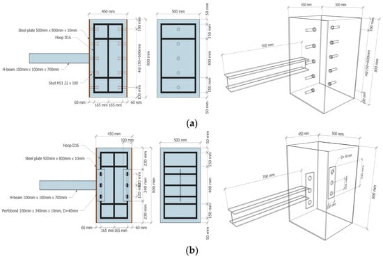
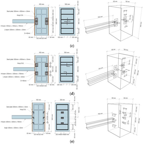
Figure 3.
Setting up a specimen to evaluate the bending performance of dissimilar member connections (schematic representation). (a) Headed stud (HS); (b) Perfobond (PB); (c) L-beam-joint (LJ); (d) L-beam-spacing (LS); (e) Angle (AN).
To evaluate the performance of dissimilar member connections, bending tests were selected as the most suitable experimental approach. To apply bending loads, an H-shaped steel beam (100 mm × 100 mm × 700 mm) was welded to one side of the steel plate as a loading arm. The SS400-grade steel was used for the H-beam to prevent deformation during the bending process.
In addition, to avoid result distortion and ensure accurate measurement by preventing premature failure outside the embedded connection zone, D13 tie reinforcements were placed around the concrete section to control cracking during the test.
2.3. Methodology
This study adopts an experimental methodology designed to clarify the structural behavior of five representative CFDS connection details under monotonic bending, which is one of the dominant loading components experienced by floating offshore substructures. The methodology consists of three stages.
First, the key performance indicators—toughness, ductility, and stiffness—were selected, as defined in Section 2.1, based on their relevance to offshore loading demands, where structural members must withstand repeated deformation while maintaining sufficient load-transfer capacity.
Second, full-scale CFDS specimens were designed with identical global dimensions to isolate the influence of connection details as the sole experimental variable. This controlled-variable approach enables direct comparison of load-transfer mechanisms, deformation characteristics, and failure modes. The steel plates used for fabricating the CFDS members were AH36 marine-grade structural steels with a nominal yield strength of 355 MPa. AH36 steel is classified as a microalloyed high-strength low-alloy (HSLA) naval structural steel, in which the required mechanical strength is primarily achieved through grain refinement promoted by the presence of microalloying elements. These microalloying additions refine the grain structure and enhance strength while maintaining a relatively low carbon content, thereby ensuring good weldability. Owing to this combination of grain-refinement strengthening and low carbon composition, AH36 steel provides reliable mechanical performance and weld integrity, making it suitable for offshore structural applications subjected to harsh marine environments. All welded joints in the CFDS specimens were fabricated using the Flux-Cored Arc Welding (FCAW) process. This welding method was selected due to its suitability for high-strength marine-grade steels such as AH36, providing sufficient penetration, stable weld quality, and enhanced formation capacity under high-heat-input fabrication conditions.
Third, a monotonic bending test configuration was selected to simulate the flexural demands applied to CFDS members in floating platforms. A servo-controlled hydraulic actuator with a maximum loading capacity of 2000 kN was used to apply the external bending load. Force and displacement responses were recorded using a high-precision data acquisition system (Tokyo Sokki Kenkyujo, Japan). Displacements were measured by CDP-type linear variable displacement transducers (LVDTs) featuring nonlinearity levels of 0.1%RO and 0.15%RO, thereby providing high-accuracy and high-output measurements suitable for structural deformation monitoring. These equipment specifications are included to ensure the reliability and accuracy of the experimental program, while the detailed configuration of the test apparatus is presented separately in Section 2.4.
This methodology ensures that the experimental program objectively captures the structural significance of each connection type and its applicability to offshore floating structures. This methodological framework also provides the basis for the experimental setup described in Section 2.4 and for the interpretation of the results presented in Section 4.
2.4. Experimental Setup and Measurement Method
The performance tests were conducted using a 2000 kN-capacity actuator with a loading rate of 2.0 mm/min. To prevent member slip and overturning during loading, the opposite side of the loaded steel plate was rigidly fixed by bolting a steel bed and clamping bar with steel rods.
To minimize measurement errors and ensure that the applied load was transmitted entirely through the H-shaped beam—thereby allowing the structural behavior of the dissimilar member connections to dominate—the upper and lower ends on the loading side were configured as free boundaries (Figure 4). The loading point was located 650 mm from the steel plate.
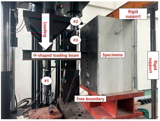
Figure 4.
Test set up.
To measure displacement behavior during loading, three Linear Variable Differential Transformers (LVDTs) were installed. As illustrated in Figure 4, LVDT #1 (Location 1) was positioned vertically at the loading point to record vertical displacement. LVDT #2 (Location 2) was installed horizontally on the loading-side steel plate, 50 mm below the top surface, while LVDT #3 (Location 3) was positioned 175 mm below the top surface, also in a horizontal orientation. The displacement data obtained from these sensors were used to analyze the deformation behavior of the connection specimens.
3. Fabrication of Specimens
The fabrication of the specimens was carried out in the following sequence: connection welding, loading component welding, steel plate assembly, and concrete casting. The detailed fabrication process is illustrated in Figure 5.
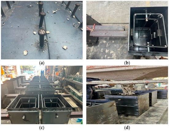
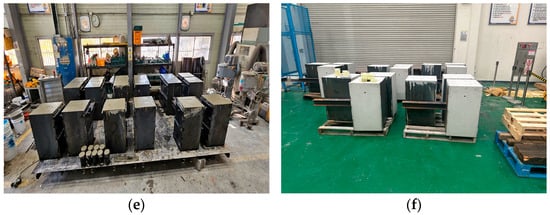
Figure 5.
Procedure for specimen preparation. (a) Welding of connections; (b) Assembly of steel plates; (c) Placement of specimen; (d) Concrete casting; (e) Preparation for curing; (f) Completion of fabrication.
First, connection components corresponding to each variable type were machined and welded at the designated positions on the outer steel plates, which serve as the external members of the CFDS structure. The steel plates with welded connections were then assembled while simultaneously placing the reinforcing bars, with the assembled plates also serving as formwork for concrete casting.
A 35 MPa-grade concrete mix was poured into the assembled steel framework. To facilitate handling and movement after casting, lifting hooks were embedded along the concrete side surfaces. After casting, the specimens were left undisturbed for three days, after which the side steel plates (excluding the connection-welded faces) were removed for demolding. The specimens were then air-cured for 28 days to complete the fabrication of fully developed CFDS structural specimens.
It should be noted that only one full-scale specimen was fabricated for each connection type. This limitation resulted from the high fabrication cost, large dimensions, and time-intensive welding and assembly processes associated with CFDS connections. As the primary objective of this study was to establish baseline behavioral trends and comparative performance characteristics among the five connection types, the single-specimen approach was adopted within the practical constraints of the experimental program. The limited number of specimens should be considered when interpreting the results, and additional tests will be required to further establish statistical confidence and quantify variability.
4. Experimental Results and Analysis
4.1. Load–Displacement Behavior
The load–displacement relationships obtained from the loading tests are summarized in Table 2 and Figure 6. Among all specimens, the Perfobond (PB) connection exhibited the highest maximum load of 45.63 kN, followed by LJ (41.42 kN), HS (32.55 kN), LS (26.07 kN), and AN (16.91 kN). The PB specimen demonstrated an approximately 40.2% higher load-bearing capacity than the HS specimen. This improvement is attributed to the reinforcing bars passing through the perforations in the Perfobond plate, which enhanced the shear confinement between the concrete core and outer steel plates, thereby improving load transfer efficiency.
Table 2.
Maximum load and displacement by connection.
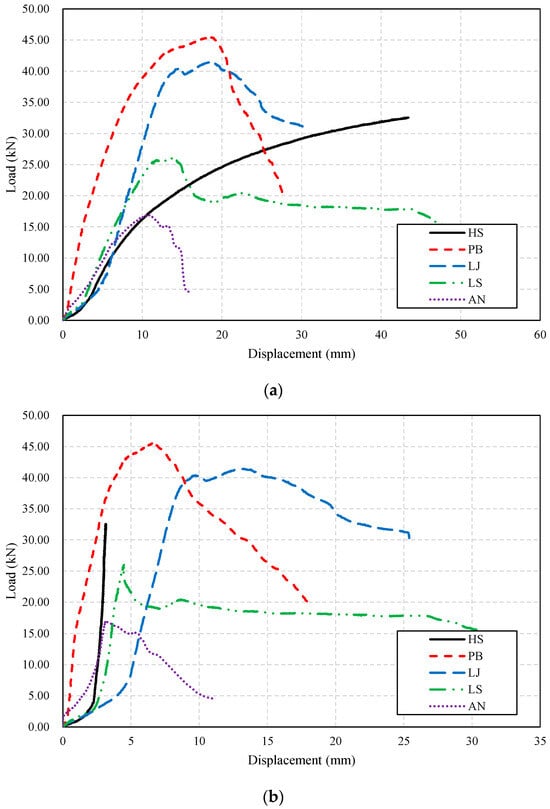
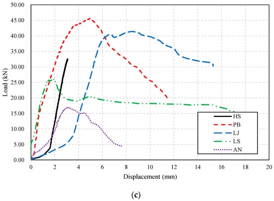
Figure 6.
Load–displacement curves by specimen type. (a) Load–displacement curve (Location 1); (b) load–displacement curve (Location 2); (c) load–displacement curve (Location 3).
The HS specimen mainly relied on bond and frictional resistance rather than intrinsic shear capacity. Consequently, its load increased more gradually, and failure initiated at a relatively low stress level, even near the peak load.
As shown in Figure 6a–c, the PB specimen exhibited a distinct linear elastic behavior at the initial stage, followed by a gradual increase in load beyond the yield point. Even after reaching the peak load, the specimen did not show an abrupt load drop, indicating that load redistribution occurred uniformly throughout the connection. This behavior typifies a ductile failure mode, in which the overall connection exhibited stable energy dissipation characteristics.
The LJ specimen displayed a similar curve shape to that of PB; however, the slope beyond the yield point was slightly gentler, and minor stiffness degradation was observed after the maximum load was reached. This phenomenon is attributed to local microcracking induced by stress concentration at the L-beam corner regions.
In contrast, the HS specimen showed a monotonic load increase up to the maximum point, without a subsequent descending branch. This indicates that the connection was completely pulled out from the concrete core during the test, causing the experiment to terminate before a clear post-peak reduction occurred. Although no apparent load drop was recorded, the behavior corresponds to brittle failure governed by localized shear stress concentration. The Headed Stud connection, which transfers load through a single shear plane, inherently lacks sufficient load redistribution capability. Therefore, without adequate confinement or bonding, HS connections are susceptible to sudden brittle failure, which poses a potential safety concern for long-term operation of floating offshore structures.
The LS specimen exhibited a low initial stiffness and irregular changes in the load–displacement slope, with a pronounced nonlinear segment where displacement increased abruptly. This early-stage behavior is primarily attributed to slip between the connector and the surrounding concrete and local deformation around the welded regions, which prevents the shear-transfer mechanism from fully engaging at the beginning of loading. As slip becomes restrained and confinement effects develop, the structural response transitions into a stiffer regime. In addition, slight eccentricity in the loading arm and fixture resulted in minor rotations that manifested as nonlinear displacement increments at small load levels. The vertically asymmetric placement of the L-beams further intensified the imbalance in shear transfer, amplifying the early-stage nonlinearity. In contrast, the PB and LJ specimens demonstrated relatively smooth initial stiffness due to their stronger confinement and more stable shear engagement. Consequently, although LS showed a relatively low maximum load, its deformation capacity was higher, reflecting a delayed but more distributed load-transfer mechanism.
The AN specimen exhibited the lowest load resistance among all specimens. Its load–displacement curve showed a short initial linear region and an early stagnation in load growth as displacement increased. This was due to the thin-angle members being vulnerable to stress concentration under combined tension and shear, while the limited bonding area between the angle and concrete failed to provide sufficient shear confinement.
Across all specimens, distinct failure characteristics were observed depending on the shear-transfer and confinement mechanisms of each connector. The HS connection exhibited a complete pull-out failure of the stud from the concrete core, accompanied by localized crushing and cracking around the embedment zone. Although minor outward bulging of the outer steel plate was observed, the dominant failure mechanism was the sudden extraction of the stud, resulting in a brittle post-peak response. This confirms that insufficient confinement and reliance on bond-type interaction governed the ultimate failure mode of the HS connector.
The PB specimens showed concrete cracking and local crushing around the web openings, followed by connector pull-out after peak load. The LJ specimens displayed stable ductile deformation with gradual interface cracking, attributed to the strong confinement provided by the L-shaped steel. The LS specimens exhibited early slip and asymmetric shear engagement, with progressive cracking around the connector region governing the failure process. The AN specimens, consistent with their limited confinement, exhibited local bearing deformation and concrete cracking at the angle–concrete contact region.
A comparison of displacement responses at the three measurement locations (Location 1–3) revealed that PB and LJ specimens exhibited uniform displacement patterns across all measurement points, indicating even load distribution. In contrast, HS and LS specimens showed asymmetric deformation behavior, with displacement concentrated at specific locations. Particularly, the HS specimen exhibited a sharp displacement increase near the loading point (Location 1), while displacement on the opposite side remained minimal, implying rapid local failure and pull-out behavior at the connection interface. This finding suggests that in practical floating structural applications, the HS connector alone is insufficient and should be complemented with reinforcing ribs or through-type shear connectors to enhance load transfer reliability.
Overall, the PB connection demonstrated the most balanced performance in terms of load transfer efficiency, ductility, and stability. The LJ connection showed high structural reliability but a slightly limited ultimate load capacity. Conversely, the HS connection was advantageous in terms of simplicity and ease of fabrication, but exhibited limited structural redundancy due to its brittle shear behavior. The LS and AN connections displayed strong position-dependent responses, implying that detailed confinement design is necessary for their practical application in floating structural systems.
To better interpret the experimental results in the context of floating offshore applications, it is important to relate the observed monotonic bending behavior to the environmental loading conditions experienced by CFDS substructures. In practical offshore settings, CFDS connections are subjected not only to monotonic bending but also to wave-induced cyclic loading, bi-axial bending, and complex combinations of tension, shear, and torsion. The behavioral characteristics identified in this study—including shear-transfer stability, initial slip, stiffness degradation trends, and deformation capacity—directly influence structural performance under such conditions. Connectors with strong confinement, such as PB and LJ, are expected to maintain stable load-transfer paths under repeated deformation, whereas connectors exhibiting initial slip or asymmetric engagement, such as HS and LS, may be more vulnerable to progressive stiffness loss or cumulative damage. Accordingly, although this study provides foundational insight into the connector-level mechanics of CFDS members, future research should incorporate cyclic, fatigue, impact, and corrosion-coupled loading to fully establish design criteria for floating offshore structures.
4.2. Energy Absorption Capacity (Toughness)
The energy absorption capacity, or toughness, is a key indicator that represents the amount of energy a structure can accumulate and dissipate before failure under external loading. It is generally divided into elastic energy () and plastic energy (), and is calculated by integrating the load–displacement curve, as expressed in Equation (1):
where is the total absorbed energy (toughness), is the elastic energy, and is the plastic energy.
The elastic energy corresponds to the area under the load–displacement curve up to approximately 80% of the maximum load, i.e., the pre-yield region, representing the recoverable energy of the structure upon unloading. The plastic energy, in contrast, corresponds to the area beyond yielding up to the maximum displacement, indicating the irreversible deformation energy associated with the structure’s resistance to fracture.
The toughness, elastic energy, and plastic energy of each connection type are shown in Figure 7 as graphs, and the corresponding numerical results are summarized in Table 3. For convenience, Location 1, Location 2, and Location 3 are denoted as L1, L2, and L3, respectively.
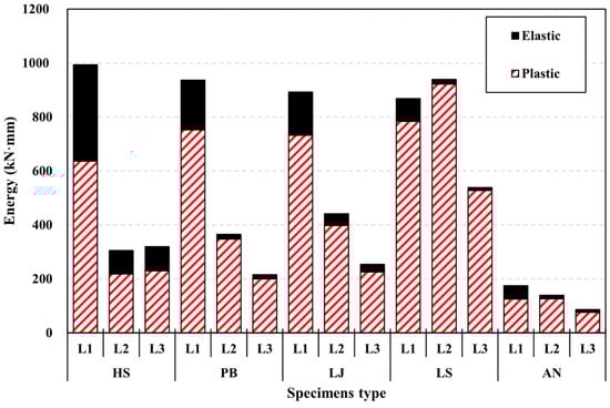
Figure 7.
Comparison of energy by specimen.
Table 3.
Energy, ductility and stiffness by specimen.
It should be emphasized that the actuator load was applied in the vertical direction, whereas the energy absorption was computed using the displacements measured at Locations 1 (vertical), 2 (horizontal), and 3 (horizontal). Consequently, only the vertical displacement represents a true work-conjugate pair with the applied load, while the horizontal displacements do not strictly satisfy this requirement. The inclusion of horizontal displacements was intended to capture localized slip and deformation occurring at the connection interface, which are not fully reflected by the global vertical displacement measurement. Therefore, the energy values derived from Locations 2 and 3 should be interpreted as comparative toughness indices rather than absolute physical work. This methodological limitation is clearly acknowledged in this manuscript. Future experimental programs will incorporate rotation-based measurements or vertical work-conjugate formulations—such as moment–rotation or load–vertical displacement relationships—to enable a more rigorous evaluation of energy dissipation.
For the representative specimen, the Perfobond (PB) connection exhibited toughness values of 937, 365, and 215 kN·mm at L1, L2, and L3, respectively. Among these, the contributions of plastic energy were 753, 348, and 200 kN·mm, accounting for 80.3%, 95.2%, and 93.0% of the total toughness. This indicates that PB possesses a high energy dissipation capacity prior to failure and tends to exhibit a ductile failure mode.
The Headed Stud (HS) specimen showed a relatively high toughness of 993 kN·mm at L1 but lower values of 305 kN·mm and 320 kN·mm at L2 and L3, respectively, confirming that energy absorption was highly localized near the loading point. At L1, the elastic and plastic energy contributions were 357 kN·mm and 636 kN·mm, corresponding to 35.9% and 64.1% of the total toughness, respectively.
The L-beam-joint (LJ) specimen exhibited toughness values of 892, 441, and 254 kN·mm at L1, L2, and L3, respectively, showing a gradual and predictable energy distribution (dominant at L1, moderate at L2, and reduced at L3). The plastic energy ratios were 82.0%, 90.2%, and 89.0%, indicating consistent behavior and high interpretative stability.
For the L-beam-spacing (LS) specimen, toughness values were 868, 939, and 539 kN·mm at L1, L2, and L3, respectively, showing a dominant energy concentration at L2. At this location, the plastic component accounted for approximately 98.2%, implying an excessive dependency on localized ductility in specific regions.
The Angle (AN) specimen exhibited the lowest energy absorption capacity among all connection types, with toughness values of 174, 139, and 86 kN·mm at L1, L2, and L3, respectively.
Overall, the PB connection demonstrated stable toughness behavior dominated by plastic energy across all locations, whereas the HS and LS specimens showed strongly position-dependent energy distributions, suggesting that their real-world performance could be significantly affected by welding quality and boundary restraint conditions. In contrast, the LJ connection exhibited a smooth and predictable energy distribution, indicating better consistency and reliability for design applications.
4.3. Ductility
Ductility refers to the deformation capacity that a structure can accommodate before reaching failure, and it has a direct influence on the failure mode and human safety during structural collapse.
It is defined as the ratio of the displacement at ultimate load (or failure) to the displacement at yielding, as expressed in Equation (2):
where is the ductility ratio, is the displacement at ultimate or failure load, and is the displacement at yielding. A higher value indicates a greater deformation capacity and better ductility performance. The ductility results for each connection type are graphically summarized in Figure 8.
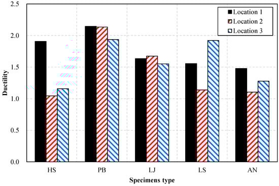
Figure 8.
Comparison of ductility by specimen.
In this study, the yield displacement was defined as the displacement corresponding to 80% of the ultimate load (0.8·). This criterion was selected because several specimens—particularly HS and LS—exhibited pronounced initial slip and multiple stiffness transitions, making it difficult to identify a distinct yield point using conventional methods such as bilinear idealization, tangent-intersection, or offset-based definitions. The 0.8· approach therefore provides a more stable, reproducible, and specimen-independent yield definition under these conditions. This criterion was applied consistently to all specimens, and the corresponding displacement values were obtained through linear interpolation when necessary.
Accordingly, the ductility ratio should be interpreted as a comparative deformation index among the five connector types rather than a strict material yield-ductility measure. For connector systems exhibiting irregular early-stage behavior, energy-based ductility indices or equivalent curvature-based measures may provide a more robust assessment framework. Future studies incorporating cyclic, multi-axial, or fatigue loading should consider these alternative metrics to avoid potential misinterpretation in design applications. Based on the yield displacement determined using the procedure described above, the ductility results for each specimen were evaluated as follows.
The Perfobond (PB) connection exhibited ductility ratios of 2.15, 2.13, and 1.94 at Locations 1, 2, and 3, respectively, showing consistently high ductility across all positions and a low likelihood of brittle failure.
In contrast, the Headed Stud (HS) specimen showed ductility ratios of 1.91, 1.04, and 1.16 at the respective locations, demonstrating sufficient ductility only at Location 1, while deformation capacity was limited at the other positions.
The L-beam-joint (LJ) connection exhibited ductility ratios of 1.63, 1.67, and 1.55, indicating a moderate and uniformly distributed ductility with minimal position dependency.
The L-beam-spacing (LS) specimen showed ductility ratios of 1.56, 1.14, and 1.92, where ductility was notably concentrated at Location 3, suggesting that this connection type is sensitive to local boundary conditions.
The Angle (AN) specimen exhibited ductility ratios of 1.48, 1.10, and 1.28, which were relatively low compared to the other connections, implying that structural reinforcement or design modification would be necessary to ensure adequate ductility.
Overall, the PB connection demonstrated the highest absolute ductility with relatively small variation among locations, indicating high reliability for design application. The LJ connection exhibited the most uniform ductility distribution, albeit at a slightly lower absolute level than PB. In contrast, the HS and LS specimens exhibited high location sensitivity, implying that their performance is strongly influenced by detailed fabrication and local confinement conditions.
4.4. Stiffness
Stiffness represents the resistance of a structure against external loading and is commonly evaluated from the slope of the load–displacement curve.
However, in this study, the load–displacement curves exhibited irregular behavior in the early region due to nonlinear and inelastic effects. To minimize the influence of these initial irregularities and pre-peak nonlinear responses, stiffness was evaluated using the slope between 20% and 80% of the maximum load, as defined in Equation (3):
where and represent 80% and 20% of the maximum load, respectively, and and are the corresponding displacements. If the exact load or displacement values at these points were not included in the recorded data, the missing values were obtained by linear interpolation between adjacent data points. The unit of stiffness is expressed in kN/mm, and the stiffness results for each connection type are graphically summarized in Figure 9.
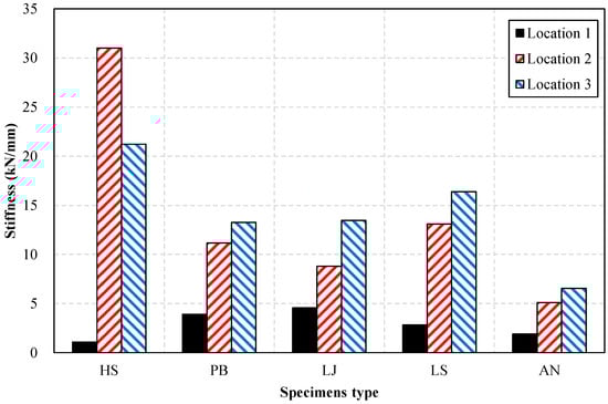
Figure 9.
Comparison of stiffness by specimen.
The Perfobond (PB) connection exhibited stiffness values of 3.90, 11.17 and 13.26 kN/mm at Locations 1, 2, and 3, respectively. The average stiffness was 9.44 kN/mm, with a range of 9.36 kN/mm—the difference between the maximum and minimum values—corresponding to approximately 99% of the average. This wide range primarily reflects the relatively low stiffness observed at Location 1, but the high values at Locations 2 and 3 indicate strong confinement and stable shear engagement. Overall, the PB connection exhibited a balanced combination of stiffness, ductility, and energy dissipation, without the severe localization observed in HS and LS. This makes PB a structurally favorable configuration, even though its stiffness was not the highest among the tested connections.
The Headed Stud (HS) specimen exhibited a localized stiffness response, with a notably low value of 1.09 kN/mm at Location 1 compared to 31.00 kN/mm and 21.23 kN/mm at Locations 2 and 3. The average stiffness was 17.77 kN/mm, and the range of 29.91 kN/mm indicates substantial positional variation. These findings imply that HS provides adequate initial resistance only at specific regions where stud–concrete interaction is fully active, making its stiffness performance sensitive to local boundary and welding conditions.
The L-beam-joint (LJ) connection showed stiffness values of 4.56, 8.80 and 13.47 kN/mm at Locations 1, 2, and 3, producing an average stiffness of 8.94 kN/mm with a moderate range of 8.91 kN/mm. This relatively narrow range indicates a predictable, mid-level stiffness response with low sensitivity to positional changes. The LJ connection therefore offers design reliability without extreme stiffness concentration or deterioration.
The L-beam-spacing (LS) connection exhibited the most uneven stiffness distribution, with values of 2.82, 13.09 and 16.38 kN/mm. The resulting average stiffness was 10.76 kN/mm, and the range reached 13.56 kN/mm— representing the second-largest variation among all configurations. The extremely high stiffness at Location 3 indicates strong dependency on local confinement and asymmetric shear transfer, suggesting that LS behavior is highly sensitive to connector positioning and may require more precise detailing in practical design.
The Angle (AN) connection demonstrated consistently low stiffness, with values of 1.90, 5.10, and 6.55 kN/mm at Locations 1, 2, and 3. Its average stiffness was 4.52 kN/mm, and the range was 4.65 kN/mm. This reflects inherently weak shear confinement and limited composite action, indicating that the AN connector would require reinforcement or geometric modification to satisfy stiffness-related design demands.
Overall, the PB connection exhibited the most balanced performance among all specimens—combining high load-carrying capacity with favorable ductility and energy dissipation—and thus represents a structurally favorable connection type for CFDS hybrid members. The HS and LS specimens showed localized high stiffness but strong position dependency, implying sensitivity to fabrication and field conditions. The LJ connection provided moderate and stable stiffness suitable for predictable design applications, while the AN connection exhibited low stiffness overall, warranting structural strengthening or design modification.
4.5. Comparative Discussion with Existing Studies
These behavioral trends are consistent with previous studies on CFDS/CFDST and other composite steel–concrete members, which have similarly reported enhanced stiffness, confinement efficiency, and ductile performance resulting from the interaction between steel skins and concrete cores [1,2,3,4,5,6,7,8,9,22]. In particular, the stable plastic deformation and high toughness observed in the PB connection agree with findings from recent studies on perfobond rib shear connectors, where perforated plate mechanisms have been shown to improve shear transfer and delay interface slip [11,12,13,24,25,26,27,28,36]. Conversely, the localized slip and reduced stiffness observed in the HS and LS connections are consistent with earlier studies on headed stud and partial shear connectors, which reported load–slip sensitivity and interface-dependent deformation under cyclic or fatigue conditions [29,30,31]. The comparatively low efficiency of the AN connection also reflects limitations identified in angle-type shear connector research, where stress concentration, limited bearing area, and asymmetric force transfer frequently govern the failure mechanism [32,33,34]. These comparisons demonstrate that the present results not only align well with contemporary findings but also extend existing knowledge by providing full-scale experimental evidence specific to CFDS hybrid members subjected to offshore-relevant bending demands.
5. Conclusions
This study successfully addresses the three research objectives proposed in the Introduction. First, the comparative evaluation of five representative CFDS connection details clarified their relative structural performance under monotonic bending, confirming the superior toughness and deformation capacity of the PB and LJ connections. Second, the experimental observations revealed the distinct deformation and failure mechanisms governing each connection type, including confinement-driven ductility, interface slip, and localized bearing effects. Third, the findings provide practical design implications for improving stiffness, ductility, and energy absorption in CFDS-based hybrid floating offshore structures. These objective-specific outcomes demonstrate that the present study not only meets its intended goals but also offers fundamental guidance for future applications and design developments. The key findings are summarized as follows:
- Within the scope of this single-specimen experimental program, the PB connection exhibited the most favorable performance among the evaluated configurations. Its maximum load reached 45.63 kN, approximately 40.2% higher than that of the HS connection. PB maintained a stable load increase beyond yielding without a sudden post-peak drop, indicating that the reinforcing bars penetrating the Perforbund plate enhanced shear confinement between the concrete core and outer steel plates, thereby improving load-redistribution efficiency.
- The HS specimen showed brittle-like failure characteristics in this test, which may warrant further verification with additional specimens. The absence of a descending branch in the load–displacement curve resulted from the complete pull-out of the connector from the concrete core, corresponding to a sudden shear failure. Since HS connectors primarily rely on bond and frictional resistance, insufficient confinement may lead to instantaneous brittle failure. Therefore, shear reinforcement or rib-type strengthening should be considered for practical applications.
- The LJ connection exhibited balanced structural behavior with relatively consistent responses across the measured locations; however, further testing is necessary to confirm its reliability. Although its maximum load was slightly lower than that of PB, it showed uniform displacement distribution across measurement locations and well-balanced performance in stiffness, ductility, and energy absorption. The LJ connection demonstrated excellent stress-redistribution capability and low sensitivity to boundary-condition variations, indicating strong potential for consistent structural behavior in real design applications.
- The LS and AN connections exhibited localized or asymmetric responses. The LS connection showed asymmetric shear-force distribution between the upper and lower L-beams, … The AN connection exhibited the lowest performance overall due to its small shear-resisting area and high vulnerability to combined tensile–shear stresses. Both connections may require geometric refinement or strengthening measures, and this tendency should be verified through additional tests because only a single specimen was evaluated for each connection type
- Achieving a balance between ductility and stiffness was identified as a critical design factor. PB and LJ connections demonstrated a favorable stiffness–ductility balance, providing both sufficient initial stiffness under service loads and adequate deformation capacity under ultimate loads. By contrast, HS and LS exhibited position-dependent energy-dissipation characteristics, indicating the need for refined detailing to ensure uniform structural performance.
In summary, although the Perfobond (PB) connection showed the most stable and well-balanced performance in terms of load-transfer efficiency, energy absorption, and ductility, this finding reflects its behavior under monotonic bending conditions only and should not be generalized to cyclic, fatigue, corrosion, or multi-axial loading environments experienced by floating offshore substructures. This observation is consistent with previous studies on PBL connectors used in double-skin tubular members [36], which also reported enhanced shear transfer and favorable flexural behavior. Nevertheless, further investigation under realistic offshore environmental loading is required before confirming the suitability of the PB connector for practical offshore applications.
All conclusions drawn in this study should be interpreted within the limitations of the single-specimen experimental program. Because only one specimen was tested for each connection type, the findings represent trend-based behavioral observations rather than statistically validated performance metrics. Additional repeated tests are required to establish variability, statistical confidence, and generalizability.
Future research should include experimental studies on cyclic and long-term fatigue behavior, corrosion–fatigue interaction, and large-scale prototype validation in offshore environments to establish comprehensive design standards for CFDS-based hybrid substructures.
Author Contributions
J.-H.P.: Investigation, Data Curation, Visualization, Writing—Original Draft. M.-S.P.: Methodology, Conceptualization. J.-W.L.: Resources, Writing—Review and Editing. All authors have read and agreed to the published version of the manuscript.
Funding
This research was supported by the Korea Institute of Energy Technology Evaluation and Planning (KETEP) and the Ministry of Trade, Industry and Energy (MOTIE) of the Republic of Korea (No. RS-2023-00238996).
Institutional Review Board Statement
Not applicable.
Informed Consent Statement
Not applicable.
Data Availability Statement
The data presented in this study are available from the corresponding author on reasonable request. The data are not publicly available due to the inclusion of proprietary experimental procedures and raw measurements containing confidential information related to ongoing research projects.
Acknowledgments
The authors would like to express their sincere appreciation to the Korea Institute of Civil Engineering and Building Technology (KICT) for providing laboratory facilities and technical assistance during the experiments. The authors also thank the Korea Institute of Energy Technology Evaluation and Planning (KETEP) and the Ministry of Trade, Industry and Energy (MOTIE) of the Republic of Korea for their research support (No. RS-2023-00238996).
Conflicts of Interest
The authors declare no conflicts of interest.
References
- Ayough, P.; Sulong, N.H.R.; Ibrahim, Z. Analysis and Review of Concrete-Filled Double Skin Steel Tubes Under Compression. Thin-Walled Struct. 2020, 148, 106495. [Google Scholar] [CrossRef]
- Gao, D.; Liu, F.; Lin, M.; Zhao, T.; Zhang, J.; He, G. The Impact Performance of Concrete-Filled Double-Skin Steel Tubes Under Seawater Corrosion: A Review. Appl. Ocean Res. 2024, 153, 104248. [Google Scholar] [CrossRef]
- Liu, J.; Shi, Y.; Guo, A. Mechanical Properties of Concrete-Filled Double-Skin Steel Tubular Columns Subjected to Axial Loading with Non-Uniform Corrosion. Structures 2024, 64, 106597. [Google Scholar] [CrossRef]
- Tian, H.-W.; Li, W.; Lai, L.-H. Tensile Performance of Concrete-Filled Double Skin Steel Tubular Members Using Recycled Aggregate Concrete. Thin-Walled Struct. 2025, 213, 113248. [Google Scholar] [CrossRef]
- Wang, F.; Cheng, Z.; Shen, J. Flexural Fatigue Behavior of Butt-Welded Circular Concrete-Filled Double Skin Steel Tube (CFDST): Experimental Study and Numerical Modeling. Mar. Struct. 2023, 88, 103380. [Google Scholar] [CrossRef]
- Vernardos, S.; Gantes, C. Experimental Behavior of Concrete-Filled Double-Skin Steel Tubular (CFDST) Stub Members Under Axial Compression: A Comparative Review. Structures 2019, 22, 383–404. [Google Scholar] [CrossRef]
- Fan, J.-H.; Wang, W.-D.; Shi, Y.-L.; Zheng, L. Low-Cycle Fatigue Behaviour of Concrete-Filled Double Skin Steel Tubular (CFDST) Members for Wind Turbine Towers. Thin-Walled Struct. 2024, 205, 112384. [Google Scholar] [CrossRef]
- Tian, H.-W.; Li, W.; Lai, L.-H. Flexural Performance of CFDST Beams Using Recycled Aggregate Concrete. J. Constr. Steel Res. 2024, 221, 108918. [Google Scholar] [CrossRef]
- Han, L.-H.; Li, Y.-J.; Liao, F.-Y. Concrete-Filled Double Skin Steel Tubular (CFDST) Columns Subjected to Long-Term Sustained Loading. Thin-Walled Struct. 2011, 49, 1534–1543. [Google Scholar] [CrossRef]
- Wang, Y.-H.; Lu, G.-B.; Zhou, X.-H. Experimental Study of the Cyclic Behavior of Concrete-Filled Double Skin Steel Tube Columns Subjected to Pure Torsion. Thin-Walled Struct. 2018, 122, 425–438. [Google Scholar] [CrossRef]
- Ahn, J.-H.; Lee, C.-G.; Won, J.-H.; Kim, S.-H. Shear Resistance of the Perfobond-Rib Shear Connector Depending on Concrete Strength and Rib Arrangement. J. Constr. Steel Res. 2010, 66, 1295–1307. [Google Scholar] [CrossRef]
- Kim, S.-H.; Kim, K.-S.; Park, S.; Ahn, J.-H.; Lee, M.-K. Y-Type Perfobond Rib Shear Connectors Subjected to Fatigue Loading on Highway Bridges. J. Constr. Steel Res. 2016, 122, 445–454. [Google Scholar] [CrossRef]
- Wang, X.; He, Q.; An, Z.; Liu, G.; Wen, X.; Wang, Y.; Zhong, Z. Experimental Study of Perfobond Rib Shear Connector Under Lateral Force. Appl. Sci. 2021, 11, 9088. [Google Scholar] [CrossRef]
- Vukelic, G.; Vizentin, G.; Ivosevic, S.; Bozic, Z. Analysis of Prolonged Marine Exposure on Properties of AH36 Steel. Eng. Fail. Anal. 2022, 135, 106132. [Google Scholar] [CrossRef]
- Pastorcic, D.; Vukelic, G.; Ivosevic, S. Welded Steel in Marine Environment—Experimental and Numerical Study of Mechanical Properties Degradation. Mater. Today Commun. 2023, 34, 105280. [Google Scholar] [CrossRef]
- Nong, Q.Q.; Dong, V.K.; Nguyen, V.T.; Nguyen, V.C.; Le, H.Q.; Cao, N.L. Protective Properties of Calcareous Deposit Layer for Cathodically Polarized AH36 Steel in Natural Seawater. Coatings 2024, 14, 644. [Google Scholar] [CrossRef]
- Qu, F.; Li, W.; Dong, W.; Tam, V.W.Y.; Yu, T. Durability Deterioration of Concrete under Marine Environment from Material to Structure: A Critical Review. J. Build. Eng. 2021, 35, 102074. [Google Scholar] [CrossRef]
- Mangi, S.A.; Makhija, A.; Raza, M.S.; Khahro, S.H.; Jhatial, A.A. A Comprehensive Review on Effects of Seawater on Engineering Properties of Concrete. Silicon 2021, 13, 4519–4526. [Google Scholar] [CrossRef]
- Hastemoglu, H.; Erkan, L. Behaviour of Double Skinned Composite Columns with Concrete Filled Tubular Columns. J. Archit. Eng. Technol. 2017, 6, 194–204. [Google Scholar] [CrossRef]
- Wang, J.; Liu, W.; Zhou, D.; Zhu, L.; Fang, H. Mechanical Behaviour of Concrete Filled Double Skin Steel Tubular Stub Columns Confined by FRP under Axial Compression. Steel Compos. Struct. 2014, 17, 431–452. [Google Scholar] [CrossRef]
- Hassan, M.M.; Mahmoud, A.A.; Serror, M.H. Behavior of Concrete-Filled Double Skin Steel Tube Beam-Columns. Steel Compos. Struct. 2016, 22, 1141–1162. [Google Scholar] [CrossRef]
- Uenaka, K. Concrete Filled Double Skin Circular Tubular Beams with Large Diameter-to-Thickness Ratio under Shear. Thin-Walled Struct. 2013, 70, 33–38. [Google Scholar] [CrossRef]
- Yan, J.-B.; Xiong, M.-X.; Qian, X.; Liew, J.Y.R. Numerical and Parametric Study of Curved Steel-Concrete-Steel Sandwich Composite Beams under Concentrated Loading. Mater. Struct. 2016, 49, 3981–4001. [Google Scholar] [CrossRef]
- He, S.; Fang, Z.; Fang, Y.; Liu, M.; Liu, L.; Mosallam, A.S. Experimental Study on Perfobond Strip Connector in Steel-Concrete Joints of Hybrid Bridges. J. Constr. Steel Res. 2016, 118, 169–179. [Google Scholar] [CrossRef]
- Sun, L.; Liu, Y.; Wang, H.; Shi, F.; Liu, J.; Jiang, L. Tensile Stiffness of Perfobond Rib Connectors in Steel-Concrete Composite Pylon of Bridges. Eng. Struct. 2023, 284, 115931. [Google Scholar] [CrossRef]
- Meng, H.; Xu, R. Bearing Mechanisms of Perfobond Rib Shear Connectors by Experimental Investigation. Eng. Struct. 2025, 326, 119576. [Google Scholar] [CrossRef]
- Sun, L.; Liu, Y.; Shi, F.; Wang, H. Pull-out Performance of Perfobond Rib Connectors in Steel High-Strength Concrete Composite Bridge Pylons. Constr. Build. Mater. 2023, 366, 130205. [Google Scholar] [CrossRef]
- Sun, L.; Liu, Y.; Han, Q.; Huang, Y.; Wang, H.; Shi, F. Pull-out Performance of Multi-Hole Perfobond Rib Connectors Embedded in High-Strength Concrete. Eng. Struct. 2025, 341, 120813. [Google Scholar] [CrossRef]
- Lu, K.; Du, L.; Xu, Q.; Yao, Y.; Wang, J. Fatigue Performance of Stud Shear Connectors in Steel-Concrete Composite Beam with Initial Damage. Eng. Struct. 2023, 276, 115381. [Google Scholar] [CrossRef]
- Xu, J.; Sun, H.; Chen, W.; Guo, X. Experiment-Based Fatigue Behaviors and Damage Detection Study of Headed Shear Studs in Steel–Concrete Composite Beams. Appl. Sci. 2021, 11, 8297. [Google Scholar] [CrossRef]
- El-Zohairy, A.; Salim, H.; Shaaban, H. Experimental Investigation on Fatigue Behavior of Composite Beams with Different Studs Arrangements. Structures 2022, 35, 146–159. [Google Scholar] [CrossRef]
- Lee, J.-S.; Shin, K.-J.; Lee, H.-D.; Woo, J.-H. Strength Evaluation of Angle Type Shear Connectors in Composite Beams. Int. J. Steel Struct. 2020, 20, 2068–2075. [Google Scholar] [CrossRef]
- Ding, K.; Zhang, X.; Liu, Y.; He, S.; Wang, J.; Shen, W. Research on Angle Connector in Composite Beam. Int. J. Concr. Struct. Mater. 2022, 16, 15. [Google Scholar] [CrossRef]
- Karakuş, B.; Arıkoğlu, P.; Topkaya, C. Experimental and Numerical Investigation of Steel-Concrete Composite Beams with Demountable Bolted Angle Shear Connectors. Eng. Struct. 2025, 341, 120858. [Google Scholar] [CrossRef]
- Fan, T.-H.; Zeng, J.-J.; Su, T.-H.; Hu, X.; Yan, X.-K.; Sun, H.-Q. Innovative FRP Reinforced UHPC Floating Wind Turbine Foundation: A Comparative Study. Ocean Eng. 2025, 326, 120799. [Google Scholar] [CrossRef]
- Mo, X.-D.; Zeng, W.-Q.; Liao, J.; Zeng, J.-J. Flexural Behavior of Hybrid FRP-Concrete-Steel Double-Skin Tubular Beams with PBL Shear Connectors. Eng. Struct. 2022, 254, 113840. [Google Scholar] [CrossRef]
- Yang, Y.; Chen, C.; Zhuang, Y.; Suo, Z. Reviewing the Progress of Corrosion Fatigue Research on Marine Structures. Front. Mater. 2024, 11, 1399292. [Google Scholar] [CrossRef]
- Mathern, A.; Von Der Haar, C.; Marx, S. Concrete Support Structures for Offshore Wind Turbines: Current Status, Challenges, and Future Trends. Energies 2021, 14, 1995. [Google Scholar] [CrossRef]
Disclaimer/Publisher’s Note: The statements, opinions and data contained in all publications are solely those of the individual author(s) and contributor(s) and not of MDPI and/or the editor(s). MDPI and/or the editor(s) disclaim responsibility for any injury to people or property resulting from any ideas, methods, instructions or products referred to in the content. |
© 2025 by the authors. Licensee MDPI, Basel, Switzerland. This article is an open access article distributed under the terms and conditions of the Creative Commons Attribution (CC BY) license.