Abstract
The rapid growth of the hydrogen industry, driven by global decarbonization efforts, has intensified the need for safe and large-capacity storage systems. Although hydrogen is one of the most abundant elements on Earth, its storage remains technically challenging due to its chemical reactivity and stringent containment requirements. Previous research has primarily emphasized the material-level behavior of polymer liners, composites, and metal alloys because chemical compatibility plays a critical role in aboveground high-pressure tanks. However, for underground storage systems, long-term structural stability is governed not only by material performance but also by the geo-mechanical behavior of deep rock masses. This study proposes a seismic design approach for Lined Rock Caverns (LRCs), a deep underground storage concept capable of sustaining high internal pressure. The method incorporates ground-induced deformation and evaluates the additional influence of internal pressure on lining behavior. Numerical analyses demonstrate that internal pressure has a significant stabilizing effect on the structural response by reducing ovalization and suppressing nonlinear deformation mechanisms. The results highlight that internal pressure is not a secondary load but a key design parameter that must be integrated into the seismic evaluation of LRC-based hydrogen storage facilities.
1. Introduction
Global energy systems are undergoing a rapid transition toward net-zero emissions, driven by international decarbonization policies and reinforced by recent assessments by the Intergovernmental Panel on Climate Change [1]. Hydrogen energy has emerged as a key element of this transition because it provides carbon-free combustion and integrates effectively with renewable power systems. Long-term global demand projections indicate that hydrogen will serve as a major energy carrier for large-capacity and long-duration energy storage in electricity, transportation, and industrial sectors. The International Energy Agency projects that global hydrogen energy demand could exceed 180 million tons per year by 2050 under accelerated transition scenarios [2,3].
Hydrogen is the most abundant element in the universe, yet usable molecular hydrogen is not readily available on Earth, making its storage a significant technical challenge [4]. Early hydrogen storage technologies relied mainly on aboveground high-pressure vessels or liquefied hydrogen tanks designed for short-term operational needs [5]. As hydrogen becomes a strategic storage medium supporting weekly to seasonal energy balancing, required storage capacities have expanded from the ton-scale to the multi-kiloton scale [3]. These demands have accelerated interest in large underground storage systems, where Lined Rock Caverns (LRCs) and repurposed geological formations are examined as practical options for long-duration and high-pressure storage [6,7,8].
Hydrogen has distinct physical and chemical characteristics that require specific engineering controls. Its minimum ignition energy is nearly an order of magnitude lower than that of gasoline, and combustion can be triggered by static discharge or minimal thermal excitation [9]. Most existing international codes focus on piping and process-safety issues for aboveground facilities. The international safety standards (i.e., API [10,11] and NFPA [12]) have been developed predominantly from a process safety perspective, focusing on piping, pressure vessels, venting, and explosion mitigation systems. Consequently, structural and geo-mechanical design provisions for deep underground hydrogen storage remain limited.
The LRC concept was developed to satisfy the containment and pressure-resistance requirements of underground gas storage. Its design integrates geological confinement with engineered components, such as reinforced concrete and a steel liner, enabling operation at pressures substantially higher than those achievable in unlined geological formations. Previous research on hydrogen storage tanks has mainly focused on material-level performance, emphasizing polymer liners, composite structures, and hydrogen barrier properties under high internal pressures [13,14]. From another perspective, LRCs must be evaluated as underground structures whose performance is governed primarily by geo-mechanical behavior rather than material optimization. Because LRCs function as long-term, permanent infrastructure, their design must ensure structural stability over the facility’s entire service life [15].
However, existing international standards provide little guidance on the seismic design of deep underground hydrogen storage. Major codes such as API [10,11] and NFPA [12] were developed primarily for aboveground pressure vessels and process-safety systems, and they do not include provisions applicable to deformation-controlled seismic loading in underground cavern environments. As a result, no standard or code currently exists for evaluating the seismic performance of LRC-based hydrogen storage facilities. This gap highlights the disconnect between material-centric tank standards and the geomechanically requirements of deep geological containment.
Although the seismic design of underground structures can be guided by established deformation-based methods developed for tunnels, these approaches are not directly applicable to high-pressure underground hydrogen storage. Conventional tunnels are unpressurized voids whose seismic performance is governed primarily by ground-induced racking deformation, as described in classical studies on underground seismic response [16,17]. In contrast, an LRC-based storage cavern contains a pressurized lining system whose structural behavior is controlled by the combined effects of internal pressure, lining–rock interaction, and free-field seismic deformation. This coupled loading condition differentiates pressure-resistant storage caverns from transportation tunnels and indicates that direct adoption of tunnel design procedures is insufficient for hydrogen storage applications.
Given the absence of seismic design provisions for deep underground hydrogen storage and the limitations of applying tunnel-based deformation methods to pressurized caverns, a systematic approach tailored to LRC systems is required. This study develops a simplified yet technically consistent seismic evaluation method that incorporates internal pressure, lining–rock interaction, and free-field ground deformation. The influence of internal pressure on the seismic response is also examined. The proposed approach and findings provide a basis for future design guidelines for large-scale, long-duration underground hydrogen storage facilities.
2. Status of Energy Storage
2.1. Classification of Energy Storage Facilities
Energy storage (ES) technologies retain generated energy and release it when required to enhance system reliability and operational flexibility. From a physical-principle perspective, ES systems are typically classified as mechanical, chemical, thermal, and electrochemical. Among these, mechanical and chemical systems dominate large-scale grid applications due to their scalability. Installation can be aboveground or underground, and seismic performance must be assessed considering facility mass and ground–structure interaction. Because storage characteristics vary widely, classification by storage medium and installation type is essential. Table 1 summarizes representative facility types.

Table 1.
Classification of Energy Storage Facilities by Storage Medium and Siting.
Mechanical energy storage includes pumped hydro storage (PHS) and Compressed Air Energy Storage (CAES). PHS uses upper and lower reservoirs to store potential energy, with dams and reservoirs constructed aboveground and waterways and tunnels installed underground [18]. CAES stores compressed air for later power generation [19]. Underground CAES employs rock caverns, salt caverns, or abandoned mines and enables large-capacity operation but requires assessment of geological suitability and long-term cavern stability. In contrast, aboveground CAES uses pressure vessels that provide lower capacity but offer simpler construction and operational flexibility.
Chemical energy storage (CES) converts electricity into chemical compounds and enables long-duration and inter-seasonal storage [20]. Representative storage media include hydrogen, synthetic fuels, and natural gas. Aboveground systems typically use high-pressure vessels, spherical tanks, or cryogenic tanks for LNG/LPG storage [21,22]. Underground CES is adopted to reduce explosion hazards and achieve large-capacity containment [23,24]. Underground hydrogen storage (UHS) has emerged as a critical option for large-scale and long-duration energy storage. Various geological formations can be utilized, including salt caverns, depleted gas reservoirs, aquifers, and lined rock caverns [25]. Salt caverns provide low permeability but require suitable geology and brine disposal. Depleted reservoirs and aquifers offer large capacity but may experience hydrogen migration, microbial activity, and gas loss which can compromise long-term containment security.
In summary, the characteristics of the storage medium are a key factor in determining the siting of energy storage facilities. For example, PHS employs large-scale dams and reservoirs aboveground to secure elevation differences, while channels and tunnels are constructed underground for efficient conveyance. CAES utilizes underground spaces such as rock caverns and salt caverns for large-scale storage, whereas aboveground pressure vessels are applied for small-scale or modular operations. For hydrogen storage, aboveground tanks that allow easy inspection and monitoring are often preferred, while engineered tanks are used aboveground for synthetic fuels and LNG/LPG because of their fire, explosion, and cryogenic risks. Overall, energy storage facilities can be broadly divided into aboveground (e.g., dams, reservoirs, LNG/LPG tanks) and underground types (e.g., tunnels, caverns), depending on storage medium, capacity, safety requirements, and geological conditions.
2.2. Hydrogen as an Energy Carrier and the Storage Challenge
Hydrogen is a major energy carrier supporting the transition toward carbon neutrality; however, large-scale storage remains challenging because of its high diffusivity, low molecular weight, and susceptibility to hydrogen embrittlement in metals [26,27]. Geological options such as salt caverns, aquifers, and depleted gas reservoirs have been investigated for underground hydrogen storage, but each presents inherent limitations. Figure 1 illustrates representative geological formations used or considered for hydrogen storage.
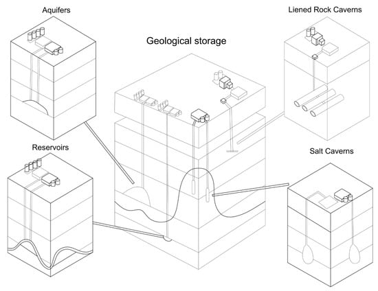
Figure 1.
Geological options for underground hydrogen storage modified from [28,29].
Salt caverns, widely used for natural gas and increasingly applied to hydrogen storage, are constrained by geological availability [30,31]. Depleted reservoirs and aquifers provide large capacity but are susceptible to hydrogen migration, microbial conversion, and mineral reactions, which can produce hydrogen sulfide or methane and compromise containment reliability [32,33]. In addition, all geological storage options depend on favorable subsurface conditions, limiting deployment to specific regions [34,35].
To overcome these limitations, the lined rock cavern (LRC) concept combines engineered and geological elements. LRCs are constructed in hard rock formations and include a reinforced concrete support layer with an inner steel or polymer liner that ensures containment [8,29,36]. The liner system prevents hydrogen leakage into the rock mass, while the concrete layer reduces permeability and provides structural support. Because LRCs do not rely on specific geological materials, they can be developed in a broader range of hard rock environments, extending applicability to regions where salt or porous formations are unavailable.
The multilayer structure distributes mechanical loads and limits hydrogen contact with rock fractures. Load transfer from the liner to the surrounding rock enhances stability under elevated internal pressure [37]. Furthermore, LRCs require less cushion gas than unlined formations due to their engineered confinement. Thermal–hydro–mechanical processes can be controlled through drainage and insulation systems, reducing corrosion and hydrogen loss.
A key feature of LRCs is their deep placement, which enables operation at high internal pressure. Geostatic stresses at depth counterbalance hydrogen pressure and contribute to structural stability [38]. Construction below the groundwater table also provides hydraulic confinement, although drainage systems are required to protect liners from corrosion [39]. Deep placement shields caverns from surface hazards and reduces land-use conflicts compared with aboveground tanks [36].
Figure 2 illustrates that LRC performance depends on the interaction among the liner, concrete, and surrounding rock. The concrete layer transfers mechanical loads and provides a stable base for liner installation [8,29]. The liner material must provide sufficient strength and resistance to hydrogen embrittlement. Insufficient design of these components can result in corrosion, instability, or hydrogen leakage.
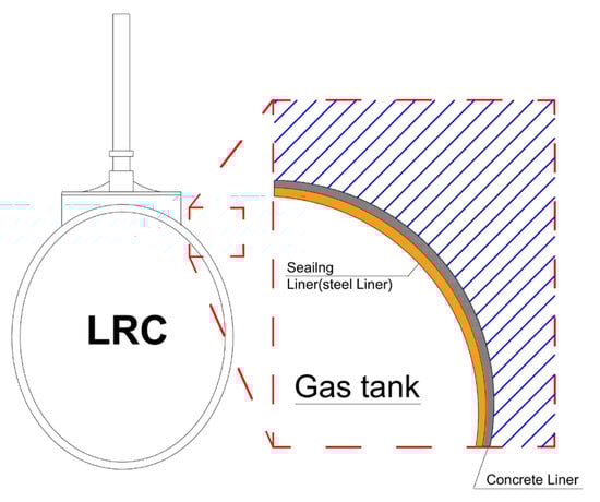
Figure 2.
Schematics for components of LRC.
3. Limitation of Existing Design Codes for Underground Hydrogen Storage
3.1. Design Codes for Hydrogen Storage
Sandia National Laboratories reviewed U.S. federal and industrial regulations for UHS and reported that no comprehensive standards currently exist for subsurface hydrogen facilities [40]. Existing codes (e.g., OSHA 29 CFR 1910.103 [41], OSHA 29 CFR 1910.119 [42], API RP 1170 and 1171 [43,44], and NFPA 2 [12]) primarily address aboveground hydrogen systems or natural-gas storage and therefore apply only limited applicability to underground configurations. EIGA DOC 06/19 [45] requires seismic checks for foundations of liquid hydrogen tanks, however, this requirement applies to surface installations rather than deep underground facilities. Because LRC-based hydrogen storage fundamentally differs from aboveground tanks in terms of structural configuration and ground–structure interaction, dedicated seismic and structural design criteria are required for UHS.
3.2. Seismic Design for Energy Storage
No dedicated design code currently exists for underground hydrogen storage, seismic design provisions from related large-scale energy storage systems must be referenced. Among them, seismic design provisions for mechanical and other storage facilities can provide a useful reference frameworks for evaluating the seismic stability of underground hydrogen storage structures. Table 2 summarizes representative seismic design standards identified through a review of existing codes applicable to large-scale energy storage facilities.
Table 2.
Representative Seismic Design Codes for Energy Storage Facilities.
The seismic design for UHS can draw upon advances in earthquake engineering developed for large-scale energy and industrial facilities. Since the mid-2000s, ASCE has expanded its seismic design provisions through successive revisions of ASCE 7, including updates to seismic hazard maps, site amplification factors, and the adoption of performance-based design concepts. In particular, ASCE 7-10 introduced major updates to seismic hazard maps and anchorage provisions [46]. In Europe, Eurocode 8 was developed in response to major historical earthquakes, including the 1906 San Francisco earthquake and the 1908 Messina earthquake [47]. Eurocode 8 provides a unified framework for the seismic design of a wide range of civil structures, including tanks, pipelines, and geotechnical systems. Pressure-vessel and pipeline design practices further adopt guidelines from the ASME BPVC [48].
The American Petroleum Institute (API) defines detailed seismic criteria for LNG and refrigerated-gas storage systems [49]. API 625 specifies three seismic hazard levels and requires that containment integrity be maintained under SSE. The standard also mandates seismic load combinations, hydrodynamic interaction at the maximum operating liquid level, and explicit consideration of soil–structure interaction (SSI). For tanks supported on soil, SSI analyses are required to evaluate differential settlement, rocking, and base-shear amplification, reflecting the significant influence of foundation flexibility on tank response.
The American Concrete Institute (ACI) provides complementary seismic provisions for reinforced concrete structures [50,51]. ACI 318 addresses ductility, confinement, and reinforcement detailing, whereas ACI 350.3 focuses on liquid-containing concrete structures and incorporates impulsive and convective hydrodynamic modes, uplift and overturning checks, and anchorage requirements. Together, these standards form a performance-based structural framework for concrete energy-storage facilities such as reservoirs, tanks, and LNG systems.
The National Fire Protection Association (NFPA) also specifies essential seismic and safety requirements for liquefied-gas facilities. NFPA 59A (LNG) defines seismic load combinations, hydrodynamic pressures, and foundation requirements, and mandates that tanks withstand the maximum credible earthquake without loss of containment. NFPA 58 (LPG) requires seismic anchorage, piping flexibility, and protection against vessel overturning and uplift. Together with API 625 and ACI 350.3, these codes establish multidisciplinary seismic design criteria integrating structural, geotechnical, and fire-safety considerations.
However, hydrogen storage facilities—which combine characteristics of high-pressure vessels and underground caverns—lack equivalent seismic provisions in NFPA, API, or ACI standards. This absence highlights a major regulatory gap, particularly for deep underground hydrogen storage, where deformation-controlled response, liner–rock interaction, and high internal pressure govern structural performance.
4. Seismic Design for LRC
4.1. Structural Characteristics of LRC
LRC and conventional tunnels exhibit similar structural characteristics because both rely on ground–lining interaction for stability. Their stability is governed primarily by the interaction between rock mass and lining system. Underground cavities are typically excavated by blasting or the New Austrian Tunneling Method (NATM). The load transfer mechanism relies on the confinement and stiffness of the rock, while the lining controls deformation and prevents collapse. However, the functional requirements of an LRC differ fundamentally from those of tunnels. Whereas tunnels resist only external geostatic and seismic loads, an LRC must resist both external confinement pressure and significant internal pressure generated by stored gas (e.g., hydrogen) [52,53].
As a result, LRCs are governed by a bidirectional loading system—internal pressure pushing outward and geostatic confinement acting inward. This dual loading leads to stress distributions and failure mechanisms that are distinct from those in conventional tunnel linings. Consequently, design requirements for LRCs must combine pressure-vessel principles with geo-mechanical interaction models, making their structural behavior more complex than that of transportation tunnels.
4.2. Material Characteristics and Comparison Between LRC Liner Steels and Tunnel Linings
According to the ASME BPVC, Section VIII [54], the minimum wall thickness of a steel vessel is determined from the hoop stress condition. For typical carbon or low-alloy steels used in hydrogen service (e.g., SA-516 Gr.70, SA-537 Cl.1), the allowable stress ranges from 120 to 160 MPa at ambient temperature. Under an internal pressure of 10 MPa and a joint efficiency of 0.85, the required wall thickness is approximately 1 m. In addition to strength, the material must meet hydrogen service requirements to prevent embrittlement and cracking. Therefore, materials must also satisfy hydrogen compatibility requirements defined by ISO 11114-4 [55] and EIGA Doc 121/14 [56].
Table 3 presents a comparison of key mechanical properties to highlight the fundamental differences between representative pressure-vessel steels (SA-516 Gr.70 and SA-537 Cl.1), commonly used in hydrogen storage applications, and conventional tunnel shotcrete. This comparison is intended to illustrate the limitations of directly applying tunnel-based design concepts to underground hydrogen storage caverns. Both steels have similar elastic modulus and density but differ in strength and service characteristics due to alloy composition and heat treatment. SA-516 Gr.70 offers good weldability and fracture toughness, whereas SA-537 Cl.1, a quenched-and-tempered steel, provides higher yield strength and ductility, making it suitable for high-pressure hydrogen environments. In contrast, tunnel shotcrete exhibits much lower stiffness, minimal tensile strength, and higher porosity. Although adequate for controlling ground deformation in tunnels, it cannot resist internal pressure or provide long-term hydrogen impermeability. Therefore, LRCs require steel liners that meet strength, ductility, and hydrogen-compatibility requirements defined in ASME BPVC Section VIII [54], ISO 11114-4 [55], and EIGA Doc 121/14 [56] to prevent hydrogen embrittlement and cracking during cyclic operation.
Table 3.
Mechanical Properties of Candidate Steels for LRC Liner Design and Concrete Lining.
4.3. Evaluation of LRC Liners Under Seismic Loading
The behavior of LRC is governed by the combined effects of internal pressure, confining ground stress, and dynamic loads generated by ground motion. The steel liner directly resists the internal hydrogen pressure, while the surrounding concrete lining and adjacent rock mass provide external confinement and transfer the resulting loads. Among these components, the shotcrete lining is typically subjected to the largest seismic demand because it bridges the interaction between the liner and the surrounding rock.
The steel liner directly resists the internal hydrogen pressure and must maintain its membrane stress within allowable limits during cyclic loading. This requirement, consistent with pressure-vessel design practice, prevents yielding, local buckling, and fatigue amplification caused by geometric imperfections or weld discontinuities.
The concrete or shotcrete lining maintains deformation compatibility and transfers loads to the surrounding rock. Because concrete exhibits low tensile capacity, its seismic performance is controlled by flexural and tensile cracking rather than compressive failure. Free-field shear strains and dynamic stress variation at the liner–rock interface can induce tensile stresses that exceed the cracking threshold. Therefore, seismic verification focuses on limiting tensile demand and ensuring adequate confinement around the liner [17,60].
Overall, the seismic safety of an LRC can be assessed with two primary checks: (1) The steel liner must remain within allowable membrane stress under combined static and dynamic pressure. (2) The concrete lining must maintain compatibility with the surrounding rock without exceeding its tensile and flexural capacity. These checks form the foundation for simplified seismic evaluation methods for deep underground hydrogen storage systems.
5. Proposed Simplified Approach for Deep Underground Storage Facilities
5.1. Simplified Seismic Evaluation Approach for Lined Rock Caverns
In the seismic analysis of deep underground tunnels, modeling the entire ground profile from the tunnel depth to the surface is rarely necessary. At deep depths, the dynamic response of the tunnel is only marginally affected by surface waves, yet full-scale dynamic modeling still requires a large computational domain and long simulation time. This extended domain increases the number of elements and boundary reflections without significantly improving the accuracy of the structural response. To address this inefficiency, the Response Displacement Method (RDM) can be applied.
The concept of the RDM was first proposed by Ambraseys and Menu [61], who suggested that the seismic effects on underground openings can be represented by imposing free-field ground deformation along the structural boundaries. This approach reproduces the essential deformation demand at the tunnel horizon while eliminating the need to explicitly model the entire overburden. As a result, the RDM provides sufficient accuracy for deformation-controlled seismic evaluation with significantly reduced computational effort.
In this approach, the free-field shear strain induced by ground motion is imposed along the model boundaries, thereby reproducing the racking deformation that develops in the surrounding rock mass. This concept is consistent with classical formulations for underground structures, in which the rock mass provides confinement and the lining deforms compatibly with the imposed ground strain. Figure 3 illustrates the deformation-controlled loading mechanism adopted in this study.
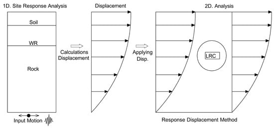
Figure 3.
Schematic diagram of design method.
In this study, a reduced-domain numerical model centered on the lined rock cavern (LRC) was employed. The reduced model adopts a square domain with a lateral extent of 1.5D from the cavern center on each side, resulting in a total model width of 3.0D. This configuration has been identified by Ahn et al. [62] as the minimum domain size required to avoid boundary effects in seismic analyses of underground tunnels. Figure 4 presents the boundary conditions adopted in the analysis.
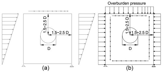
Figure 4.
Schematic modeling of RDM from [62]: (a) displacement boundary conditions applied (b) shear stress applied.
When applying the RDM, two modeling strategies can be adopted depending on how the initial in situ stress state is treated: (1) an initial step in which the excavation process and in situ stress redistribution are explicitly modeled, followed by a seismic step; and (2) a seismic-only step in which the initial stress field is neglected and only the effects of imposed shear deformation are simulated. In the present study, displacement-controlled boundary conditions were employed. In this case, the stresses acting on the initial lining configuration were first obtained from a separate static analysis and then superimposed with those induced by the imposed shear deformation to determine the total stress response.
The LRC lining was modeled using two-node beam elements, while the surrounding ground was represented by solid elements employing the Constant Strain Triangular (CST) formulation. To represent the nonlinear response of the ground, either the SIG3 or the Mohr–Coulomb constitutive model was adopted, depending on the soil or rock characteristics.
The free-field ground deformation input for the RDM analysis was computed using one-dimensional equivalent-linear site response analysis [63]. An effective shear strain coefficient of 0.65 was adopted, and the iterative solution was repeated ten times until convergence was achieved. Layer thicknesses were assigned to ensure accurate transmission of seismic waves up to 25 Hz, thereby preventing numerical filtering of high-frequency components. The input motion was applied as a rock outcrop acceleration record, ensuring that downward-propagating shear waves were prevented from reflecting into the analysis domain.
The internal pressure of the LRC can be represented using Möller’s β-method [64], an effective correction approach for load distribution. This method incorporates the three-dimensional effects, which are arching behavior and stress concentration along the sidewalls, considering a two-dimensional numerical analysis. Therefore, by applying the modified β-method, the internal pressure of hydrogen storage caverns can be modeled more realistically, would be providing a practical means to approximate the confinement interaction under internal pressurization within a simplified 2D analysis.
5.2. Numerical Results and Stress Response of the LRC
Two-dimensional finite-element analyses were performed using PLAXIS 2D 2025.1.1 under plane-strain conditions, and the response displacement method (RDM) was applied to simulate seismic-induced ground deformation. Incremental horizontal displacements were imposed along the lateral boundary to represent free-field ground deformation. The tunnel diameter was set to 20 m, and the model domain extended to 1.5D in the vertical direction and 2.5D in the horizontal direction to minimize boundary effects, as shown in Figure 5.
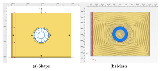
Figure 5.
Modeling Shape and Mesh for Numerical Analysis.
The surrounding ground was discretized using constant strain triangular (CST) elements. The numerical model consisted of approximately 130,000 elements, providing sufficient spatial resolution throughout the analysis domain. Mesh refinement was applied around the lined rock cavern and along the model boundaries, where stress concentration and deformation gradients were expected under displacement-controlled loading. Away from the cavern, a sufficiently fine mesh density was maintained to reduce mesh dependency and ensure numerical stability.
The surrounding ground was modeled as a single layer of competent deep hard rock using the Mohr–Coulomb constitutive model. The assumed rock mass is representative of crystalline rock formations, such as granite or gneiss, commonly encountered at depth. The adopted material properties fall within the typical ranges reported in previous numerical studies on lined rock caverns and deep underground openings subjected to internal pressure (e.g., [6,15,54]). In this study, the rock mass was assumed to be homogeneous and isotropic, as the primary objective was not to investigate site-specific geological conditions, but to evaluate the fundamental interaction between internal pressure, ground-induced deformation, and lining response. This simplified representation has been widely adopted in previous LRC studies to examine deformation-controlled behavior while avoiding additional uncertainties associated with complex stratigraphy or discontinuities.
The shotcrete lining and steel liner were represented by plate elements, and a thin contact layer was inserted between them to avoid numerical issues associated with direct plate-to-plate contact. Interface elements were included at all material boundaries. Material properties are summarized in Table 4 and Table 5.
Table 4.
Properties of Rock and Contacted layer.
Table 5.
Properties of Shotcrete and Steel Lining.
The bottom boundary was fully fixed, while the right boundary was constrained horizontally and free vertically. The left boundary was assigned a displacement-controlled condition for the RDM, with horizontal displacements of 1, 2, 3, 5, and 10 cm applied incrementally. Internal pressure was applied to the inner surface of the steel liner as a radially outward load with magnitudes of 0, 50, 60, 70, 80, 90, and 100 kPa.
For each analysis case, the maximum and minimum circumferential values of horizontal displacement, vertical displacement, axial force, shear force, and bending moment were extracted. These results are summarized in Table 6.
Table 6.
Maximum and Minimum Value of Analysis Results.
Figure 6 and Figure 7 present the lining response patterns under internal pressure only and under combined internal pressure and RDM boundary displacement, respectively. In these figures, the deformed lining shape is shown together with a length-based magnitude scale, where larger legend values indicate greater deformation amplitudes. The magnitude scale represents the absolute deformation of the lining and is provided to facilitate qualitative comparison of deformation patterns rather than direct quantitative evaluation at specific points. Comparison of the two figures indicates that the application of RDM boundary displacement alters the locations of critical response along the lining compared to the pressure-only condition.
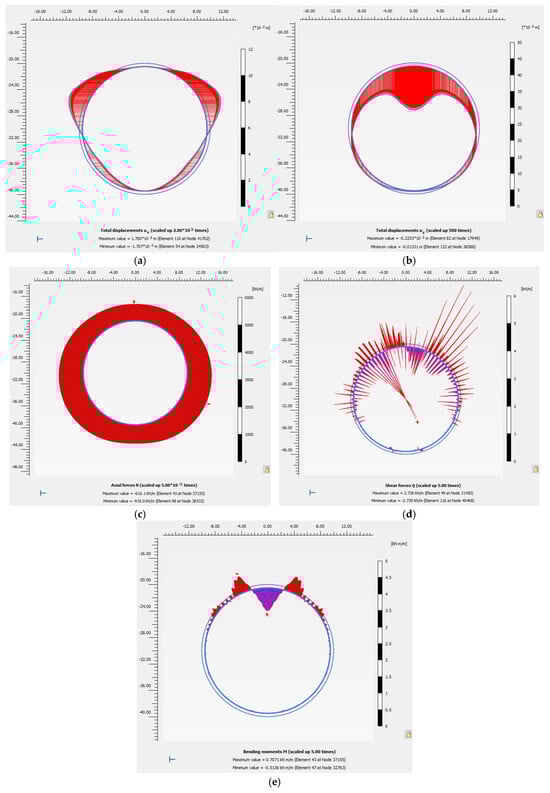
Figure 6.
Lining behavior shape under internal pressure only (Pressure 100 kPa). (a) Maximum Horizontal Displacement. (b) Minimum Vertical Displacement. (c) Axial force. (d) Shear force. (e) Bending moment.
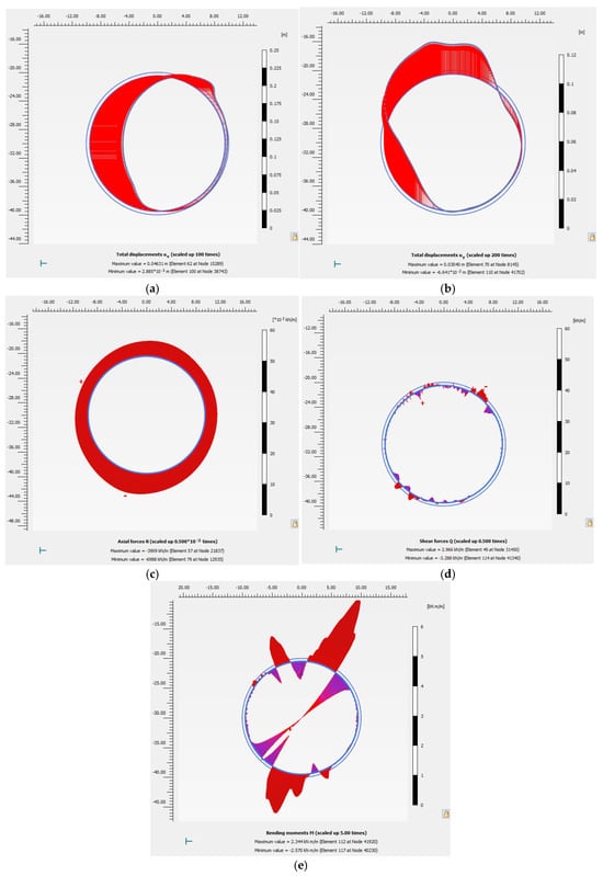
Figure 7.
Lining behavior shape under RDM conditions (Pressure 100 kPa, RD 50 mm). (a) Maximum Horizontal Displacement. (b) Minimum Vertical Displacement. (c) Axial force. (d) Shear force. (e) Bending moment.
5.3. Lining Response Under Combined Internal Pressure and Ground Displacement
Figure 8 summarizes the displacement response of the lining under imposed ground displacement for internal pressures of 70, 80, 90, and 100 kPa. The internal pressure values correspond to the gas pressure applied to the inner surface of the lining. For consistency among pressure cases, results are presented up to a boundary displacement of Δ = 10 cm.
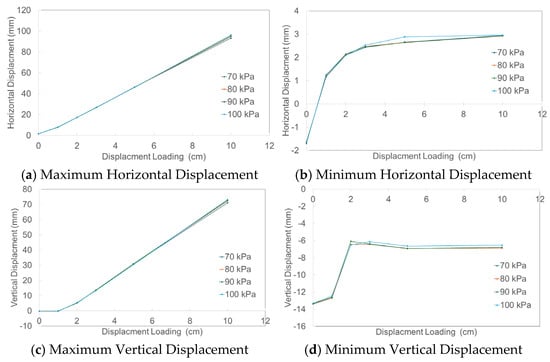
Figure 8.
Displacement Behaviors.
Figure 8 summarizes the displacement response of the lining under imposed ground displacement for internal pressures of 70, 80, 90, and 100 kPa. The internal pressure values correspond to the gas pressure applied to the inner surface of the lining, rather than a surcharge load. For consistency and reliable comparison among different pressure cases, the results are presented up to a boundary displacement of Δ = 10 cm for all cases. Although the analysis at p = 100 kPa converged at larger displacement levels in the preliminary simulations, such results were excluded to avoid potential numerical instability and to maintain consistency across pressure cases.
For each displacement increment (Δ = 1, 2, 3, 5, and 10 cm), both horizontal and vertical displacements increase approximately linearly. At a fixed displacement level, differences among pressure levels are small. For example, the maximum horizontal displacement under p = 100 kPa increases from 17.24 mm to 96.22 mm as Δ increases from 2 cm to 10 cm. At Δ = 5 cm, differences in maximum horizontal displacement among 80–100 kPa are on the order of 1 mm. Minimum horizontal displacement shows a similar trend. Vertical displacement exhibits comparable behavior, increasing quasi-linearly with Δ.
Figure 9 presents the variation in axial force, shear force, and bending moment with imposed ground displacement. Axial force increases monotonically with Δ for all pressure levels. At small displacement levels, the response curves for different pressures nearly overlap, while slight divergence appears at larger displacements. Shear force increases approximately linearly with Δ, showing some dispersion among pressure levels, particularly at small displacement amplitudes. Bending moment also increases with Δ, with a steeper growth rate observed at larger displacement levels.
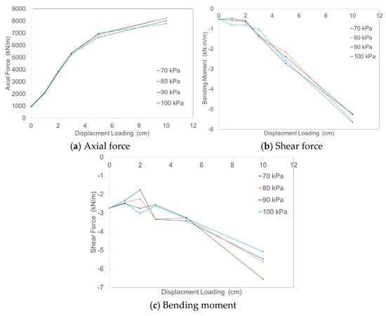
Figure 9.
Displacement Loading versus Force Behaviors of Lining.
Figure 10 shows the relationship between lining forces and the maximum horizontal displacement. Axial force increases consistently with displacement, with pressure-dependent differences becoming noticeable only at larger displacement levels. Shear force exhibits greater variability at small displacements and decreases nearly linearly at larger displacements. Bending moment increases approximately linearly with displacement, with relatively small differences among pressure levels.
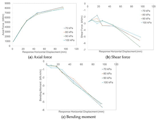
Figure 10.
Maximum Response Horizontal Displacement versus Force Behaviors of Lining.
6. Discussion
6.1. Nonlinear Response and Convergence Behavior Under Reduced Internal Pressure
Table 6 indicates that internal pressures of 70 kPa or higher result in stable and linear convergence under stepwise RDM boundary displacements up to 10 cm. In contrast, at 60 kPa, the numerical model converges only under the no-displacement condition and fails to converge when boundary displacement is applied, producing numerical errors such as load advancement failure. This behavior reflects a transition into a nonlinear response regime characterized by steep displacement and force gradients and localized discontinuities.
The reduction in internal pressure diminishes the stabilizing effect of hoop action in the lining, allowing bending-dominated deformation to develop under imposed ground displacement. As a result, localized slip or opening at the lining–ground interface is activated, intensifying geometric nonlinearity and leading to snap-through or snap-back behavior with loss of numerical convergence.
6.2. Role of Hoop Action in Lining Stability
The internal pressure induces a hoop force in the circular lining, which can be approximated as . For a lining radius of 10 m and an internal pressure of 0.1 MPa, the resulting hoop force is approximately 1000 kN/m in the present model.
As the internal pressure decreases toward 60 kPa, the reduction in hoop force causes the lining response to shift from membrane-dominated behavior to bending-dominated deformation under imposed displacement. This promotes ovalization and rapid activation of slip or opening at the interface, producing localized shear concentration. For pressure levels of 70–100 kPa, the hoop force is sufficient to suppress local opening and pre-buckling behavior, allowing a larger portion of the imposed deformation to be carried by membrane action, thereby stabilizing the response.
6.3. Critical Internal Pressure and Design Implications
For practical design, it is necessary to establish a critical internal pressure that reflects site conditions and section properties. Based on the present analyses, the critical internal pressure is estimated to be approximately 60–70 kPa, and a minimum operating pressure of at least 70 kPa is recommended. During normal operation, an internal pressure of 100 kPa (0.1 MPa) reduces sensitivity to bending and shear demands and mitigates fatigue effects. Approaching 70 kPa should therefore trigger a low-pressure alarm.
During seismic or large-deformation events, maintaining or increasing internal pressure is structurally advantageous. In contrast, pressure levels near 60–70 kPa may induce rapid slip or opening at the interface and lead to potential irreversible damage.
6.4. Design Considerations Under Combined Displacement and Pressure Effects
The numerical results demonstrate that, under combined response displacement and internal pressure, the global deformation of the lined rock cavern is primarily governed by the imposed ground displacement (Δ), rather than by the magnitude of internal pressure. Within the investigated pressure range of 70–100 kPa, both horizontal and vertical lining displacements increase quasi-linearly with Δ, while differences among pressure levels at a fixed Δ remain small. This indicates that increasing internal pressure has limited effectiveness in reducing overall lining deformation.
The relatively small differences in displacement response observed among different internal pressure levels can be attributed to the displacement-controlled nature of the Response Displacement Method (RDM) adopted in this study. Under RDM conditions, the global deformation of the lining is governed primarily by the imposed ground displacement, whereas internal pressure plays a secondary role by enhancing response stability and reducing sensitivity to local instability rather than by directly limiting deformation magnitude.
From a mechanical perspective, internal pressure mainly contributes to lining stability through the generation of hoop force, which enhances membrane action and improves numerical and structural robustness. However, this hoop-force effect does not significantly restrain global deformation induced by ground movement. Instead, deformation control is more strongly influenced by lining stiffness parameters, such as thickness and elastic modulus, as well as by the limitation of external ground displacement demand.
The internal force responses further clarify this behavior. Axial force increases monotonically with increasing Δ, largely independent of internal pressure, particularly in the small-displacement range where all pressure cases show nearly overlapping trends. At larger displacements, slight divergence among pressure levels is observed, reflecting the combined influence of hoop-force–induced stress redistribution and asymmetric deformation along the lining. Nevertheless, axial force remains predominantly displacement-controlled.
In contrast, shear force and bending moment exhibit greater sensitivity to internal pressure under large displacement demands. Higher internal pressure tends to amplify bending moments due to membrane–bending coupling, while its influence on shear force depends on interface behavior and local stick–slip transitions. These effects become pronounced near the spring line and crown, where curvature demand and shear transfer concentrate under asymmetric deformation modes.
From a design standpoint, these findings imply that limiting external ground displacement should be regarded as the primary seismic performance objective for deep underground storage caverns. While maintaining sufficient internal pressure is beneficial for stabilizing the lining and preventing premature opening or slip at the ground–lining interface, excessive reliance on internal pressure for deformation control is not justified. Under combined adverse conditions—namely, large ground displacement and high internal pressure—shear and bending checks must be performed concurrently, and localized reinforcement measures, such as increased lining thickness, stiffening rings, or enhanced joint detailing, should be considered in critical regions.
7. Conclusions
This study assessed the seismic performance of lined rock caverns (LRCs) for underground hydrogen storage by integrating a review of existing design codes, structural characterization of LRC systems, and numerical evaluation based on a reduced-domain Response Displacement Method (RDM). The main findings can be summarized as follows.
- Hydrogen’s physical characteristics and the need for long-term, large-capacity storage highlight the importance of deep underground facilities. Among available geological options, LRCs provide high impermeability, applicability across diverse rock formations, and suitability for pressurized operation. However, unlike surface tanks or pressure vessels, their seismic behavior is governed by ground–lining interaction under deformation-controlled loading rather than by vessel-type response alone.
- A review of domestic and international standards confirmed that no existing seismic design provisions explicitly address underground hydrogen storage caverns. Current codes, including ASCE 7, Eurocode 8, API 620/625, ACI 350.3, and NFPA 59A, focus on dams, LNG tanks, or pressure vessels and do not consider key aspects of LRC behavior, such as imposed ground deformation, internal pressure–lining interaction, or deformation-controlled loading mechanisms. This regulatory gap underscores the need for a dedicated seismic design framework for LRC-based hydrogen storage.
- The structural characteristics of LRCs differ fundamentally from those of conventional tunnels. While both rely on confinement and lining stiffness, LRCs must additionally sustain internal pressure through a multilayer system consisting of a steel liner, concrete support, and competent surrounding rock. The mechanical behavior of pressure-vessel steel differs markedly from that of tunnel shotcrete, confirming that conventional tunnel design approaches cannot be directly applied to pressurized underground storage caverns.
- Numerical analyses based on the RDM demonstrated that internal pressure plays a critical role in stabilizing the lining response under imposed ground deformation. A pressure range of approximately 60–70 kPa was identified as a transition zone between unstable and stable behavior. Below this range, reduced hoop action leads to bending-dominated deformation, ovalization, interface slip or opening, and loss of numerical convergence. For internal pressures of 70 kPa or higher, the lining response remains stable and convergent under stepwise ground displacement. Axial force was found to dominate the structural demand, while shear force and bending moment become significant primarily at large displacement levels.
- These findings indicate that seismic design of LRCs should treat internal pressure as a functional stability parameter rather than as a secondary load. Maintaining sufficient internal pressure during ground deformation enhances lining stability and robustness, and a minimum operational pressure of approximately 70 kPa is recommended. Given the absence of applicable design provisions in current codes, the results provide a rational basis for developing performance-based seismic design guidelines for underground hydrogen storage caverns.
- Future research should extend the present work to three-dimensional modeling, cyclic and cumulative damage effects, thermal–hydro–mechanical coupling, and nonlinear rock mass behavior, in order to support the formulation of comprehensive and codified seismic design provisions for underground hydrogen storage facilities.
Author Contributions
S.-W.S.: writing—original draft preparation, analysis, J.-W.L.: writing—review, visualization. J.-K.A.: writing—original draft preparation, methodology. C.P.: writing—review and editing, project administration, supervision. All authors have read and agreed to the published version of the manuscript.
Funding
This research was supported by the Regional Innovation System & Education (RISE) program through the Gangwon RISE Center, funded by the Ministry of Education (MOE) and the Gangwon State (G.S.), Republic of Korea (2025-RISE-10-002).
Data Availability Statement
The original contributions presented in this study are included in the article. Further inquiries can be directed to the corresponding author.
Conflicts of Interest
The authors declare no conflicts of interest.
References
- Intergovernmental Panel on Climate Change (IPCC). Climate Change 2023: Synthesis Report; IPCC: Geneva, Switzerland, 2023. [Google Scholar]
- International Energy Agency (IEA). Global Hydrogen Review 2022; IEA: Paris, France, 2022. [Google Scholar]
- International Energy Agency (IEA). Net Zero Roadmap: A Global Pathway to Keep the 1.5 °C Goal in Reach; IEA: Paris, France, 2023. [Google Scholar]
- Sarmah, M.K.; Singh, T.P.; Kalita, P.; Dewan, A. Sustainable hydrogen generation and storage—A review. RSC Adv. 2023, 13, 25253–25275. [Google Scholar] [CrossRef] [PubMed]
- Perna, A.; Minutillo, M.; Di Micco, S.; Jannelli, E. Design and costs analysis of hydrogen refuelling stations based on different hydrogen sources and plant configurations. Energies 2022, 15, 541. [Google Scholar] [CrossRef]
- Damasceno, D.R.; Spross, J.; Johansson, F. Rock mass response for lined rock caverns subjected to high internal gas pressure. J. Rock Mech. Geotech. Eng. 2023, 15, 119–129. [Google Scholar] [CrossRef]
- Gianni, E.; Tyrologou, P.; Couto, N.; Carneiro, J.F.; Scholtzová, E.; Koukouzas, N. Underground hydrogen storage: The techno-economic perspective. Open Res. Eur. 2024, 4, 17. [Google Scholar] [CrossRef]
- Masoudi, M.; Hassanpouryouzband, A.; Hellevang, H.; Haszeldine, R.S. Lined rock caverns: A hydrogen storage solution. J. Energy Storage 2024, 84, 110927. [Google Scholar] [CrossRef]
- Calabrese, M.; Portarapillo, M.; Di Nardo, A.; Venezia, V.; Turco, M.; Luciani, G.; Di Benedetto, A. Hydrogen safety challenges: A comprehensive review on production, storage, transport, utilization, and CFD-based consequence and risk assessment. Energies 2024, 17, 1350. [Google Scholar] [CrossRef]
- API Standard 620; Design and Construction of Large, Welded, Low-Pressure Storage Tanks. American Petroleum Institute (API): Washington, DC, USA, 2002.
- API Standard 625; Tank Systems for Refrigerated Liquefied Gas Storage. American Petroleum Institute (API): Washington, DC, USA, 2010.
- National Fire Protection Association (NFPA). NFPA 2: Hydrogen Technologies Code, 2023 Edition; NFPA: Quincy, MA, USA, 2023. [Google Scholar]
- Dagdag, O.; Kim, H. Recent advances in the hydrogen gas barrier performance of polymer liners and composites for type IV hydrogen storage tanks: Fabrication, properties, and molecular modeling. Polymers 2025, 17, 1231. [Google Scholar] [CrossRef]
- Thangarasu, S.; Oh, T.H. Impact of polymers on magnesium-based hydrogen storage systems. Polymers 2022, 14, 2608. [Google Scholar] [CrossRef]
- Liu, S.; Zhang, D. Study on long-term stability of lined rock cavern for compressed air energy storage. Energies 2024, 17, 5908. [Google Scholar] [CrossRef]
- Wang, J.N. Seismic Design of Tunnels: A Simple State of the Art Design Approach; Parsons Brinckerhoff Inc.: New York, NY, USA, 1993. [Google Scholar]
- Hashash, Y.M.A.; Hook, J.J.; Schmidt, B.; Yao, J.I.-C. Seismic design and analysis of underground structures. Tunn. Undergr. Space Technol. 2001, 16, 247–293. [Google Scholar] [CrossRef]
- Nikolaos, P.C.; Marios, F.; Dimitris, K. A review of pumped hydro storage systems. Energies 2023, 16, 4516. [Google Scholar] [CrossRef]
- Jankowski, M.; Pałac, A.; Sornek, K.; Goryl, W.; Żołądek, M.; Homa, M.; Filipowicz, M. Status and development perspectives of compressed air energy storage (CAES) technologies—A literature review. Energies 2024, 17, 2064. [Google Scholar] [CrossRef]
- Elliot, J.; Brown, J.; Mlilo, N.; Bowtell, L. Global trends in community energy storage: A comprehensive analysis. Sustainability 2025, 17, 1975. [Google Scholar] [CrossRef]
- Pellegrini, L.A.; Moioli, S.; Brignoli, F.; Bellini, C. LNG technology: The weathering in above-ground storage tanks. Ind. Eng. Chem. Res. 2014, 53, 3931–3937. [Google Scholar] [CrossRef]
- Sarvestani, K.; Ahmadi, O.; Alenjareghi, M.J. LPG storage tank accidents: Initiating events, causes, scenarios, and consequences. J. Fail. Anal. Prev. 2021, 21, 1305–1314. [Google Scholar] [CrossRef]
- Tarkowski, R. Underground hydrogen storage: Characteristics and prospects. Renew. Sustain. Energy Rev. 2019, 105, 86–94. [Google Scholar] [CrossRef]
- Sun, J.; Sun, D.; Asif, M.; Fang, B.; Bai, Y.; Qin, W.; Pan, T.; Jiang, J.; Zhang, M.; Wang, Z. Safety distance of ground and underground petrochemical installations. J. Loss Prev. Process Ind. 2021, 69, 104355. [Google Scholar] [CrossRef]
- Hematpur, H.; Abdollahi, R.; Rostami, S.; Haghighi, M.; Blunt, M.J. Review of underground hydrogen storage: Concepts and challenges. Adv. Geo-Energy Res. 2023, 7, 111–131. [Google Scholar] [CrossRef]
- Ahad, M.T.; Bhuiyan, M.M.H.; Sakib, A.N.; Corral, A.B.; Siddique, Z. Overview of challenges for the future of hydrogen. Materials 2023, 16, 6680. [Google Scholar] [CrossRef]
- Yu, H.; Díaz, A.; Lu, X.; Sun, B.; Ding, Y.; Koyama, M.; He, J.; Zhou, X.; Oudriss, A.; Feaugas, X.; et al. Hydrogen embrittlement as a conspicuous material challenge. Chem. Rev. 2024, 124, 6271–6392. [Google Scholar] [CrossRef]
- Griffioen, J.; van Wensem, J.; Oomes, J.L.; Barends, F.; Breunese, J.; Bruining, H.; Olsthoorn, T.; Stams, A.J.; van der Stoel, A.E. A technical investigation on tools and concepts for sustainable management of the subsurface in The Netherland. Sci. Total Environ. 2014, 485–486, 810–819. [Google Scholar] [CrossRef] [PubMed]
- Patanwar, Y.K.; Kim, H.M.; Deb, D.; Gujjala, Y.K. Underground storage of hydrogen in lined rock caverns: Key components and embrittlement issues. Int. J. Hydrogen Energy 2024, 50, 116–133. [Google Scholar] [CrossRef]
- Caglayan, D.G.; Weber, N.; Heinrichs, H.U.; Linßen, J.; Robinius, M.; Kukla, P.A.; Stolten, D. Technical potential of salt caverns for hydrogen storage in Europe. Int. J. Hydrogen Energy 2020, 45, 6793–6805. [Google Scholar] [CrossRef]
- Małachowska, A.; Łukasik, N.; Mioduska, J.; Gębicki, J. Hydrogen storage in geological formations—Potential of salt caverns. Energies 2022, 15, 5038. [Google Scholar] [CrossRef]
- Dopffel, N.; Jansen, S.; Gerritse, J. Microbial side effects of underground hydrogen storage. Int. J. Hydrogen Energy 2021, 46, 8594–8606. [Google Scholar] [CrossRef]
- Khajooie, S.; Gaus, G.; Dohrmann, A.B.; Krüger, M.; Littke, R. Methanogenic conversion of hydrogen to methane in reservoir rocks. Int. J. Hydrogen Energy 2024, 50, 272–290. [Google Scholar] [CrossRef]
- Aftab, A.; Hassanpouryouzband, A.; Xie, Q.; Machuca, L.L.; Sarmadivaleh, M. Toward a Fundamental Understanding of Geological Hydrogen Storage. Ind. Eng. Chem. Res. 2022, 61, 3233–3253. [Google Scholar] [CrossRef]
- Qian, X.; You, S.; Wang, R.; Yue, Y.; Liao, Q.; Dai, J.; Tian, S.; Liu, X. Underground hydrogen storage in salt caverns. Sustainability 2025, 17, 5900. [Google Scholar] [CrossRef]
- Sofregaz, U.; Gustafsväg, C. Commercial Potential of Natural Gas Storage in Lined Rock Caverns; US DOE: Washington, DC, USA, 1999. [Google Scholar]
- Ryu, D.; Kim, H.; Park, D. Rock engineering in underground compressed air energy storage. In Rock Mechanics and Engineering; CRC Press: Boca Raton, FL, USA, 2017; Volume 3, pp. 549–578. [Google Scholar]
- Zivar, D.; Kumar, S.; Foroozesh, J. Underground hydrogen storage: A comprehensive review. Int. J. Hydrogen Energy 2021, 46, 23436–23462. [Google Scholar] [CrossRef]
- Marchiori, L.; Albuquerque, A.; Pais, L.A.; Boscov, M.E.G.; Cavaleiro, V. Geoenvironmental engineered structures for water protection. Sustainability 2025, 17, 1850. [Google Scholar] [CrossRef]
- Louie, M.S.; Ehrhart, B.D. Regulations, Codes, and Standards Review for Underground Hydrogen Storage; Sandia National Laboratories: Livermore, CA, USA, 2024. [Google Scholar]
- OSHA. 29 CFR 1910.103—Hydrogen. Available online: https://www.osha.gov/laws-regs/regulations/standardnumber/1910/1910.103 (accessed on 2 June 2023).
- OSHA. 29 CFR 1910.119—Process Safety Management. Available online: https://www.ecfr.gov/ (accessed on 18 April 2024).
- API RP 1170; Design and Operation of Solution-Mined Salt Caverns. American Petroleum Institute (API): Washington, DC, USA, 2022.
- API RP 1171; Functional Integrity of Natural Gas Storage. American Petroleum Institute (API): Washington, DC, USA, 2022.
- European Industrial Gases Association (EIGA). Safety in Storage, Handling and Distribution of Liquid Hydrogen; Doc 06/19; EIGA: Brussels, Belgium, 2019. [Google Scholar]
- Ghosh, S.K. Significant changes from ASCE 7-05 to ASCE 7-10, Part 1: Seismic design provisions. PCI J. 2014, 59, 16–29. [Google Scholar] [CrossRef]
- Bisch, P. Introduction: Seismic design and Eurocode 8. In Seismic Design of Buildings to Eurocode 8; CRC Press: Boca Raton, FL, USA, 2016; pp. 15–20. [Google Scholar]
- Karcher, G.G.; Ecoff, R.A. Recent advances in ASME pressure vessel codes. J. Press. Vessel Technol. 1981, 103, 119–124. [Google Scholar] [CrossRef]
- API Standard 650; Low-Pressure Storage Tanks. American Petroleum Institute (API): Washington, DC, USA, 2018.
- ACI Committee. Code Requirements for Environmental Engineering Concrete Structures (ACI 350-01); ACI: Farmington Hills, MI, USA, 2001. [Google Scholar]
- ACI 318-05; Building Code Requirements for Structural Concrete. ACI Committee: Farmington Hills, MI, USA, 2005.
- Zhou, S.W.; Xia, C.C.; Du, S.G.; Zhang, P.Y.; Zhou, Y. Mechanical responses of lined rock caverns under temperature and air pressure. Rock Mech. Rock Eng. 2015, 48, 749–770. [Google Scholar] [CrossRef]
- Bowen, H.; Xianzhen, M.; Yu, L.; Shuchen, L.; Wei, L.; Chao, W. Effects of cushion gas pressure and operating parameters on hydrogen storage capacity in LRC. Renew. Energy 2024, 235, 121317. [Google Scholar] [CrossRef]
- ASME. Boiler and Pressure Vessel Code, Section VIII, Div. I.; ASME: New York, NY, USA, 2023. [Google Scholar]
- ISO 11114-4; Transportable Gas Cylinders—Compatibility of Cylinder and Valve Materials with Gas Contents—Part 4. ISO: Geneva, Switzerland, 2017.
- European Industrial Gases Association (EIGA). Hydrogen Pipeline Systems; Doc 121/14; EIGA: Brussels, Belgium, 2014. [Google Scholar]
- ASTM A516/A516M-21; Standard Specification for Carbon Steel Pressure Vessel Plates. ASTM: West Conshohocken, PA, USA, 2021.
- ASTM A537/A537M-20; Standard Specification for Pressure Vessel Plates, Heat-Treated Carbon-Manganese-Silicon Steel. ASTM: West Conshohocken, PA, USA, 2020.
- Korea Concrete Institute. Design Code for Shear and Torsion of Concrete Structures (KDS 14 20 22). MLIT: Seoul, Republic of Korea, 2024.
- Wang, G.; Yuan, M.; Miao, Y.; Wu, J.; Wang, Y. Seismic response of tunnel–soil–surface structure interaction. Tunn. Undergr. Space Technol. 2018, 76, 145–159. [Google Scholar] [CrossRef]
- Ambraseys, N.N.; Menu, J.A.M. Earthquake-induced ground displacements. Earthq. Eng. Struct. Dyn. 1988, 16, 985–1006. [Google Scholar] [CrossRef]
- Ahn, J.K.; Park, D.H.; Kim, D.K.; Kim, K.Y. Evaluation of seismic performance of operating road tunnels. J. Korean Tunn. Undergr. Space Assoc. 2013, 15, 69–80. (In Korean) [Google Scholar]
- Hashash, Y.M.A.; Musgrove, M.I.; Harmon, J.A.; Ilhan, O.; Groholski, D.R.; Phillips, C.A.; Park, D. DEEPSOIL 7.0 User Manual; Univ. of Illinois: Urbana-Champaign, IL, USA, 2017. [Google Scholar]
- Möller, S.C. Tunnel Induced Settlements and Structural Forces in Linings. Ph.D. Thesis, Universität Stuttgart, Stuttgart, Germany, 2006. [Google Scholar]
Disclaimer/Publisher’s Note: The statements, opinions and data contained in all publications are solely those of the individual author(s) and contributor(s) and not of MDPI and/or the editor(s). MDPI and/or the editor(s) disclaim responsibility for any injury to people or property resulting from any ideas, methods, instructions or products referred to in the content. |
© 2025 by the authors. Licensee MDPI, Basel, Switzerland. This article is an open access article distributed under the terms and conditions of the Creative Commons Attribution (CC BY) license.