Abstract
In this work, an effective control framework is proposed for a two-wheeled mobile robot (TWMR) operating under time-varying disturbances and uncertain system parameters. To enhance robustness against these uncertainties, an integral sliding mode control (ISMC) method is adopted. A mathematical model of the TWMR is obtained in the state form, and an ISMC law is designed. The proposed control law comprises two terms: a nominal term and a discontinuous term. The nominal term is designed based on the linearized model and optimal control to eliminate any steady-state error, while the discontinuous term is designed based on the sliding surface and the reaching law to force the system state onto the sliding surface under changing disturbances and parameter variations. These two terms are combined to constitute the overall control law. The performance and robustness of the proposed method are assessed through simulation under different uncertainty conditions of the TWMR.
1. Introduction
A two-wheeled mobile robot (TWMR) is a type of robot with three degrees of freedom (3-DOF) that uses two wheels on the right and left sides. TWMRs are underactuated and highly nonlinear systems that cannot maintain self-balancing and drive without constant control of the two wheels’ speed and direction against gravity and uncertainties. TWMRs have gained increasing popularity in a variety of consumer and industrial applications due to their relatively simple structure, versatility, and ability to access narrow workspaces. These systems have been the subject of extensive research interest worldwide for several decades, dating back to William G. Walter’s development of the first electronic autonomous robot, known as the tortoise, in 1948 [1]. Recent research studies have focused on improving the performance, perception, and autonomy of TWMRs. One area of active research is the improvement of control algorithms to ones that can better handle disturbances and uncertainties. The existing methods to stabilize and drive TWMRs include system modeling [2,3,4], PID control [5,6,7], optimal control [8,9,10], H∞ control [11], model predictive control (MPC) [12,13], intelligent control [14,15,16,17], sliding mode control (SMC) [18,19,20,21,22,23], and feedback linearization [24].
Among the studies related to the modeling of TWMRs, the authors of [2] obtained a 1-DOF model of a monoaxial bicycle while dealing with the postural control problem of its tilt angle. In [3], the authors investigated the dynamics of a two-wheeled inverted pendulum robot and examined the robot’s behavior on an inclined surface, as well as its turning effects and stability. The authors of [4] analyzed the kinematics of a robot’s wheels and body separately and then established the whole kinematics model of the robot system.
Early control studies on TWMRs predominantly employed PID control strategies. In [5], the authors developed a wheeled mobile robot equipped with a pair of DC motors, a driver board, an STM32 microcontroller, and two Hall sensors, and applied a PID algorithm to regulate the rotational speeds of the DC motors. In [6], a single tethered robot was modeled as a MIMO system, and both a conventional PID controller and a fuzzy PID controller with self-tuning scaling factors were designed to achieve the desired control performance. In [7], a two-wheeled self-balancing robot model subject to road disturbance effects was established and simulated using MATLAB (2021a) Simscape Multibody, where robot balancing and stability were achieved through PID control and linear quadratic regulator (LQR) approaches tailored to specific control objectives.
The work presented in [8] developed a nonlinear optimal control strategy for a two-wheeled inverted pendulum (TWIP) mobile platform subject to parameter uncertainties, utilizing the state-dependent Riccati equation approach. They developed a state-dependent coefficient matrix for the control law based on the dynamic characteristics of the TWIP mobile platform. The authors of [9] proposed an adaptive LQR control method for a TWMR with unknown system dynamics and disturbances to track the desired trajectory, wherein an adaptive observer was adopted to estimate the unknown system states and disturbances in real time. The authors of [10] proposed a model-free LQR control method for a TWMR using a deep neural network and reinforcement learning to approximate the Q-function of the LQR controller. In [11], a robust LQR controller combined with an H∞ control scheme was developed for a TWMR operating under uncertainties and external disturbances to ensure satisfactory closed-loop stability and performance.
In [12], a hierarchical cascade control scheme was developed for a two-wheeled robot manipulator with varying mass. An adaptive MPC was implemented in the inner loop to regulate the fast-varying center-of-gravity angle, while an outer-loop linear quadratic Gaussian (LQG) controller generated the reference set-point. The authors of [13] proposed an MPC optimized via a genetic algorithm (GA) to improve the trajectory tracking effect of Mecanum-wheeled mobile robots (MWMRs), where the MPC considered the mechanical and speed constraints of the MWMRs, as well as the changes in the curvature of the tracking trajectory.
In [14], a dual-loop adaptive type-II fuzzy control scheme was proposed for wheeled mobile robots (WMRs) operating under wheel slip and external disturbances. The outer loop addresses position tracking and the inner loop regulates velocity tracking, with each loop combining a stabilizing feedback controller and an adaptive type-II fuzzy controller to compensate for unknown dynamics. Another fuzzy control study for a differential-drive wheeled mobile robot performing path-following was reported in [15], where the parameters of all fuzzy logic controller membership functions were automatically optimized using a GA. In [16], a fuzzy controller incorporating an LQR was designed for a TWMR to direct the orientation of the chassis. The parameters of the LQR were computed using a GA. The authors of [17] developed an intelligent system consisting of two neural networks for the control of a wheeled robot. The architecture employs two networks: one to identify the obstacle’s position and size, and the other to generate a continuous trajectory toward the destination while accounting for the acquired information, destination coordinates, and terminal orientation.
Recently, the application of nonlinear control techniques for TWMRs has attracted the attention of researchers [18,19,20,21,22,23,24]. In [18], a nonlinear sliding mode controller for a TWMR was proposed to track a desired trajectory in the presence of disturbances and uncertainties. In [19], an adaptive sliding mode-based fault-tolerant controller for WMRs under actuator faults, disturbances, and unknown system parameters was proposed, where the adaptive law adjusts the parameters of the SMC in real time. The study in [20] proposed a robust adaptive output-feedback trajectory tracking controller for a wheeled mobile robot (WMR) based on the sliding mode super-twisting algorithm. The study in [21] proposed a robust control framework that integrates adaptive observer design with sliding mode control to address terrain inclination and disturbances in a two-wheeled self-balancing robot, enabling estimation of unmeasured states and the inclination angle. In [22], a control scheme combining sliding mode control with modern control techniques was presented for a two-wheeled inverted pendulum. A robust integral sliding mode controller was designed to address short- and long-term disturbances, constant uncertainties, and parameter variations. In [23], a backstepping control algorithm with speed compensation control was proposed to solve the path tracking control problem of mobile robots under nonholonomic constraints and external interference factors. While these control methods provide satisfactory performance, there remains significant room for improvement, particularly concerning computational efficiency and implementation complexity. Specifically, advanced techniques like adaptive SMC and high-order SMC require complex, resource-intensive computations for both implementation and stability proofs. Likewise, the recursive nature of the backstepping algorithm causes it to suffer from an explosion of complexity, where the resulting control law becomes computationally burden as the system’s order increases.
Therefore, we present a design for a TWMR tracking controller combining an LQR and SMC. The objective of this study is to utilize the benefits offered by both the optimal nature and robustness of SMC. First, a nominal term is designed based on the linearized model of the TWMR and optimal control theory to eliminate any steady-state error. Subsequently, a discontinuous control term is designed based on the sliding surface and reaching law to drive the system states onto the sliding surface in the presence of time-varying disturbances and parameter variations. Then, the two terms are combined to constitute the overall control law. The effectiveness of the proposed method is illustrated through a set of simulation works. The organization of this paper is as follows: Section 1 provides an introduction. Section 2 describes the mathematical modeling of a TWMR system. Section 3 describes the integral sliding mode control (ISMC) design based on SMC and an LQR. Section 4 simulates the closed-loop system and compares its performance with that of the SMC.
2. Mathematical Modeling of a TWMR System
2.1. Nonlinear Model
The first step in designing a control law that properly guides a TWMR to a desired signal is to construct its mathematical model. A TWMR can rotate around its body’s vertical axis and can also move backward and forward along the central axis between its two wheels. Figure 1 shows the coordinate system of the TWMR.
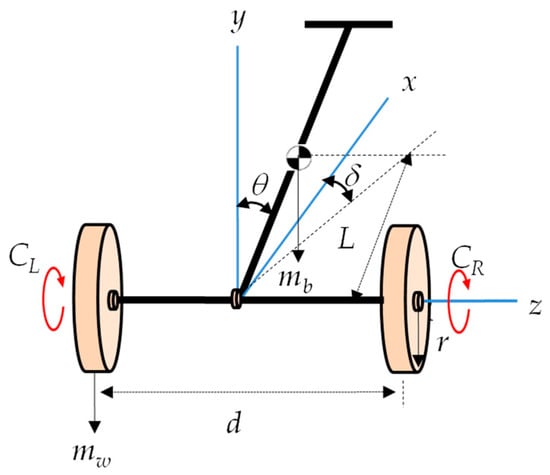
Figure 1.
TWMR coordinate system.
Recently, a variety of mathematical descriptions of TWMRs have been presented in the literature [2,3,4]. By applying the Newton–Euler or Lagrangian method, a nonlinear dynamic model of a TWMR can be derived in the following form:
where is the inertia matrix, is the centrifugal and Coriolis force matrix, is the gravity vector, is the input matrix, is the input vector, and . , , and are the position of the wheel [m], the pitch angle [rad], and the yaw angle [rad] of the TWMR, respectively.
By taking the inverse of and defining the state vector , the control input vector , and the output vector , Equation (1) can be rewritten in the nonlinear state space form
with
where , , , and , , and are the corresponding time derivatives.
The functions in Equation (2) are given by
where and with constant terms , , and . The parameters employed in Equation (2) are defined in Table 1.

Table 1.
Physical parameter values of a magnetic levitation train system.
2.2. Linearized Model
By choosing the origin as an equilibrium point of the system—that is, setting and —and applying the Taylor series approximation, Equation (2) can be represented in state space form as
where , , , and , , and are 6, 2, and 2, respectively. The Jacobian matrices of partial derivatives are given by
with coefficients
It can be verified that the pair (, ) in Equation (10) is controllable with the parameters in Table 1.
2.3. Model with Uncertainties
As expected, the linearized model is valid in a small region around the equilibrium point. In order to express Equation (10) more closely to the nonlinear model in Equation (2), we further consider uncertainties in the following form:
where is the uncertainty due to model dynamics and/or external disturbances, and is a matrix with appropriate dimensions. Some assumptions are considered:
- 1.
- , and the pair (, ) is controllable.
- 2.
- is unknown but upper-bounded for all .
- 3.
- is known and lies in the range space of matrix ; therefore, it is possible to write for some .
Then, Equation (21) can be rewritten as
In order to design a tracking controller for the TWMR, a new state vector is defined as follows:
where is the desired signal, and . Differentiating both sides of Equation (23) and combining it with Equation (22) yields the following augmented system:
where
Note that the augmented system in Equation (24) is controllable if the pair (, ) of the original system has rank and the following condition is satisfied [24]:
3. Design of an Integral Sliding Mode Control Law
Sliding mode control (SMC) forces the system states to converge to a pre-defined sliding surface and slide along it until they enter the reaching phase. SMC typically consists of two components: a nominal (equivalent) control and a discontinuous (switching) control [25,26]. The nominal control is responsible for forcing the system state to move towards the sliding surface, while the discontinuous control is responsible for positioning the system state on the sliding surface and keeping it there to achieve the desired performance characteristics. Since the objective of this work is to design a robust control law for the system in Equation (21) that is insensitive to uncertainties and external disturbances, we assume that the integral sliding mode control (ISMC) law also has two components, nominal control and discontinuous control , defined as follows:
3.1. Nominal Control Law
A nominal controller is derived for the nominal system by neglecting the uncertain components in Equation (24).
Then, the feedback control law is obtained as
where the gain matrix can be obtained in several ways, but we apply optimal control theory so that the quadratic cost function is minimized.
Here, is a positive semi-definite matrix and is a positive definite matrix. They penalize deviations from the desired state and control effort. is obtained as
where is the solution of the Riccati equation
Rewriting Equation (29) together with Equation (23) results in
where .
3.2. Discontinuous Control Law
The ISMC is developed using a sliding surface and a reaching law, with the design process divided into two parts: defining an integral sliding surface on which the sliding motion occurs and designing a control law that ensures the system states converge to and remain on the specified sliding surface.
For ISMC, the following sliding surface is defined:
where denotes the design freedom and induces the integral term. can be selected as the left pseudo-inverse of , such that is invertible:
During the sliding mode, . Differentiation of the sliding surface yields
Substituting Equations (24) and (27) into Equation (36) gives
From the condition that the 4 terms related to the nominal control must be 0,
Integrating Equation (38) with the initial condition and substituting this into Equation (34) gives the sliding surface
where guarantees to eliminate the reaching phase.
From the condition that the remaining two terms related to the discontinuous control in Equation (37) must be 0, the discontinuous control is designed as
where is the unit vector component, and is a positive constant.
3.3. Overall Control Law
The nominal control and the discontinuous control are combined to form a single control input. Thus, the overall control law in Equation (27) becomes
If we want to further mitigate the chattering effect, can be replaced by one of its continuous approximations [26].
The finite time convergence of the feedback system is proved by the Lyapunov approach.
Theorem 1.
The uncertain system in Equation (24) can be asymptotically stabilized with the integral sliding surface in Equation (34) and the control law in Equation (41), ifis chosen such that the conditionis satisfied.
Proof.
Choose a Lyapunov function as follows:
The sufficient condition for the existence of a sliding mode is that [25,26]
In order to prove the condition in Equation (43), we first differentiate Equation (34) and then substitute Equation (24) into it.
Substituting Equations (28), (38), and (41) into Equation (44) and rearranging yields
Pre-multiplying both sides of Equation (45) by yields
and through the property , Equation (46) becomes
Applying the property again to Equation (29) gives
If we choose a positive scalar such that
where is a small positive constant, the condition in Equation (43) is satisfied. As can be seen from Equation (49), if the value of is greater than upper bound of uncertainty, the Lyapunov function is gradually decreasing and the sliding surface tends to zero in the given time. □
4. Simulation Results and Discussion
In this section, we describe a set of simulation works carried out on the nonlinear model in Equation (2) to demonstrate the efficiency of the proposed method. The results were compared with those of sliding mode control (SMC). The SMC uses Equation (33) as nominal control, but removes the integral element from the sliding plane in Equation (34). The tracking performance was quantitatively assessed using standard metrics: overshoot (), rise time (), settling time (), and the integral absolute error (), where . To measure robustness during disturbance rejection and parameter variation, we calculated the and the peak perturbation (). is defined as the maximum absolute deviation from the output.
4.1. System Parameters and Controller Settings
The weighing matrices and are generally chosen to achieve a trade-off between tracking performance and control effort. In this study, they were chosen through trial and error to ensure an acceptable transient response while the system is less affected by measurement noise. With the choice of
the feedback gain matrices and were obtained as
For the discontinuous control , was chosen to be and was set to 2.5 by considering the upper bound of .
4.2. Performance Under Setpoint Changes
To illustrate the tracking performance of the proposed method, a closed-loop TWMR system without uncertainties was evaluated for step-type reference changes. The following desired signals and initial conditions were configured for two different simulation cases:
- Case 1: Reference and initial condition ;
- Case 2: Reference and initial condition .
Figure 2 and Figure 3 show the responses of the position, pitch angle, and yaw angle for both Case 1 and Case 2. It can be seen from Figure 2 and Figure 3 that the position and yaw angle converged to each desired value within 4 s, whereas the pitch angle maintained self-balancing within 4 s.
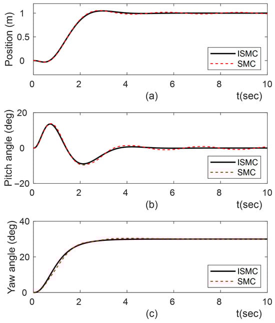
Figure 2.
Tracking responses of ISMC and SMC for . (a) position; (b) pitch angle; (c) yaw angle.
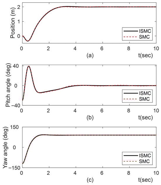
Figure 3.
Tracking responses of ISMC and SMC for . (a) position; (b) pitch angle; (c) yaw angle.
We calculated , , , and of the outputs to quantitatively measure the performance of the proposed method. Table 2 summarizes these results.
Table 2.
Tracking performance under reference input changes.
Comparing the results in Table 2, the ISMC’s overshoot observed in Case 2 was marginally larger than that of Case 1. In both cases, the of ISMC is shown to be less than that of SMC.
4.3. Performance Under External Disturbance
A second simulation was conducted to test the proposed method’s robustness to external disturbances, such as stones or irregularities in the terrain, which can transmit external torque to the wheels when the TWMR travels on the terrain. Disturbance in the form of a trigonometric function was applied to the left and right wheels at 2 s after the outputs approached the desired value from the initial state . Figure 4 shows the responses of the position, pitch angle and yaw angle. It can be clearly seen that the proposed ISMC maintained all states near steady-state values with minimal oscillation, whereas the SMC exhibited more oscillatory responses due to input chattering.
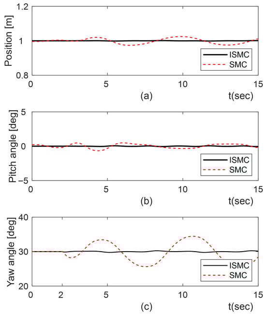
Figure 4.
Disturbance rejection responses of ISMC and SMC under disturbances. (a) position; (b) pitch angle; (c) yaw angle.
To quantitatively demonstrate the disturbance rejection performance, we calculated and and summarized them in Table 3. Table 3 confirms the superiority of our method.
Table 3.
Regulating performance under disturbance.
4.4. Performance Under Disturbance Plus Parameter Changes
A third simulation was conducted to confirm the robustness of the proposed method to both external disturbances and parameter changes. Considering that the mass of the wheels slightly changes due to mud when the TWMR drives on a muddy road, four parameters were changed by adding about 40% of their nominal values: , , , and . We applied the disturbance at 2 s while tracking the setpoint from the initial state . Figure 5 shows the responses of the closed-loop system.
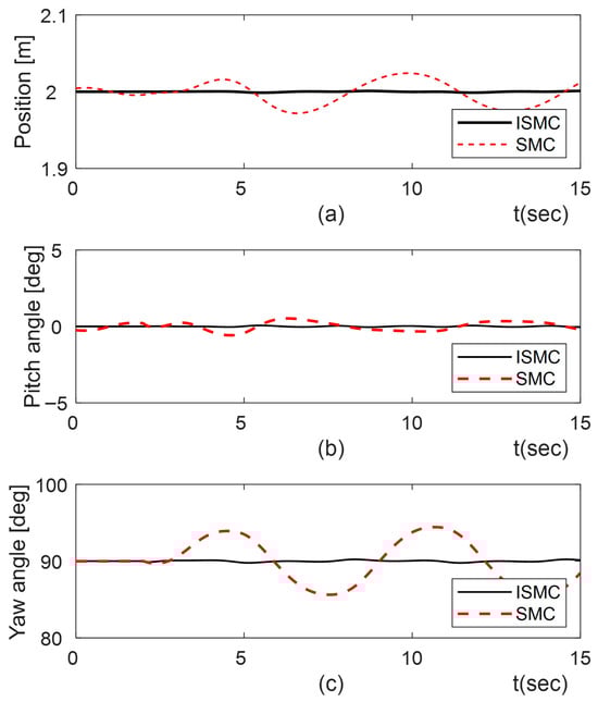
Figure 5.
Responses for ISMC and SMC under disturbances and parameter variations. (a) position; (b) pitch angle; (c) yaw angle.
The figures clearly demonstrate that the proposed ISMC completely eliminated uncertainties, resulting in stable responses, whereas the SMC continued to exhibit oscillations. Table 4 summarizes the results of and . This evidence highlights the superior robustness of the proposed ISMC.
Table 4.
Regulating performance under disturbance and parameter variations.
5. Conclusions
In this paper, we proposed an integral sliding mode control (ISMC) strategy for controlling the position and yaw angle and self-stabilizing the pitch angle of a TWMR. In order to maintain control under time-varying disturbances and parameter variations in the TWMR, a nonlinear mathematical model using Newtonian law was obtained, and a control law consisting of nominal and discontinuous control was derived. The nominal control was designed based on the linearized model and optimal control theory. In order to design a tracking controller, an augmented model was used. The discontinuous control was designed such that it successfully rejects disturbances and parameter variations. Finally, a set of simulation studies were performed to evaluate the performance and robustness of the proposed method under different uncertainty conditions. The TWMR control using ISMC with optimal features was more robust and more effective than SMC. The transition of the proposed control law to real-world systems necessitates future investigations into special areas including nonlinear observer design for estimating unmeasurable variables and IIR filter design for mitigating sensor noise.
Author Contributions
Conceptualization, methodology, software, writing—original draft preparation, L.F.N.; investigation, L.F.N., G.-G.J. and J.A.; writing—review and editing, validation, and visualization, G.-G.J., G.S. and J.A.; supervision, G.-G.J. and J.A.; project administration, G.-G.J. and J.A.; funding acquisition, J.A. All authors have read and agreed to the published version of the manuscript.
Funding
This research was supported by the Regional Innovation System & Education (RISE) program through the RISE Center, Gyeongsangnam-do, funded by the Ministry of Education (MOE) and the Gyeongsangnam-do Provincial Government, Republic of Korea. (2025-RISE-16-001) [Workation-2025-0106].
Data Availability Statement
The original contributions presented in this study are included in the article. Further inquiries can be directed to the corresponding author.
Conflicts of Interest
The authors declare no conflicts of interest.
Abbreviations
The following abbreviations are used in this manuscript:
| DOF | Degree of freedom |
| GA | Genetic algorithm |
| IAE | Integral Absolute Error |
| ISMC | Integral sliding mode control |
| LQG | Linear quadratic Gaussian regulator |
| LQR | Linear quadratic regulator |
| MPC | Model predictive control |
| MWMRs | Mecanum-wheeled mobile robots |
| PID | Proportional–Integral–Derivative |
| SMC | Sliding mode control |
| TWIP | Two-wheeled inverted pendulum |
| TWMR | Two-wheeled mobile robot |
References
- Hayward, R. The Tortoise and the Love-Machine: Grey Walter and the Politics of Electroencephalography. Sci. Context 2001, 14, 615–641. [Google Scholar] [CrossRef] [PubMed]
- Yamajuji, K.; Kawamura, T. Postural control of a monoaxial bicycle. J. Robot. Soc. Jpn. 1989, 7, 74–79. [Google Scholar] [CrossRef]
- Kim, S.; Kwon, S.J. Dynamic Modeling of a Two-wheeled Inverted Pendulum Balancing Mobile Robot. Int. J. Control Autom. Syst. 2015, 13, 926–933. [Google Scholar] [CrossRef]
- He, B.; Zhen, L.; Feng, H. The Kinematics Model of a Two-Wheeled Self-Balancing Autonomous Mobile Robot and Its Simulation. In Proceedings of the 2010 Second International Conference on Computer Engineering and Applications, Bali, Indonesia, 19–21 March 2010. [Google Scholar] [CrossRef]
- Meng, J.; Liu, A.; Yang, Y.; Wu, Z.; Xu, Q. Two-Wheeled Robot Platform Based on PID Control. In Proceedings of the 2018 5th International Conference on Information Science and Control Engineering (ICISCE), Zhengzhou, China, 20–22 July 2018. [Google Scholar] [CrossRef]
- Salehpour, M.H.; Taghirad, H.D.; Moradi, H. Two PID-Based Controllers for a Tethered Segway on Dome Shaped Structures. In Proceedings of the 2018 6th RSI International Conference on Robotics and Mechatronics (IcRoM), Tehran, Iran, 23–25 October 2018. [Google Scholar] [CrossRef]
- Mohsin, H.H.; Aldair, A.A.; Al-Hussaibi, W.A. Robust Control Design for Two-Wheel Self-Balanced Mobile Robot. Iraqi J. Electr. Electron. Eng. 2023, 19, 38–46. [Google Scholar] [CrossRef]
- Kim, S.T.; Kwon, S.J. Nonlinear Optimal Control Design for Underactuated Two-Wheeled Inverted Pendulum Mobile Platform. IEEE/ASME Trans. Mechatron. 2017, 22, 2803–2808. [Google Scholar] [CrossRef]
- Wang, Z.; Zhang, L. Height Adaptive LQR Control of a Two-Wheel Legged Robot via Closed-Loop Frequency Identification. In Proceedings of the 2025 5th International Conference on Computer, Control and Robotics (ICCCR), Hangzhou, China, 16–18 May 2025; pp. 145–151. [Google Scholar]
- Guo, L.; Asad Rizvi, S.A.; Lin, Z. Optimal control of a two-wheeled self-balancing robot by reinforcement learning. Int. J. Robust Nonlinear Control 2021, 31, 6205–6222. [Google Scholar] [CrossRef]
- Wang, Z.; Li, C.; Zhang, L. An Integrated LQR and Sliding Mode Controller for Balance and Motion Control of a Five-Link Two-Wheel Legged Robot. In Proceedings of the 26th Annual Conference Towards Autonomous Robotic Systems (TAROS 2025), York, UK, 20–22 August 2025; pp. 138–151. [Google Scholar] [CrossRef]
- Önkol, M.; Kasnakoğlu, C. Adaptive Model Predictive Control of a Two-wheeled Robot Manipulator with Varying Mass. Meas. Control 2018, 51, 38–56. [Google Scholar] [CrossRef]
- Li, Y.; Qiu, L.; Wang, Z.; Zhou, J.; Guo, Y. Adaptive model predictive control for trajectory tracking of Mecanum mobile robots. J. Adv. Mech. Des. Syst. Manuf. 2019, 13, 1–15. [Google Scholar]
- Ha, V.Q.; Pham, S.H.-T.; Vu, N.T.-T. Adaptive Fuzzy Type-II Controller for Wheeled Mobile Robot with Disturbances and Wheelslips. J. Robot. 2021, 2021, 6946210. [Google Scholar] [CrossRef]
- Štefek, A.; Pham, V.T.; Krivanek, V.; Pham, K.L. Optimization of Fuzzy Logic Controller Used for a Differential Drive Wheeled Mobile Robot. Appl. Sci. 2021, 11, 6023. [Google Scholar] [CrossRef]
- Jahromi, Z.K.; Shishavan, H.K. A New Approach for Control of Two-wheeled Mobile Robot. Univers. J. Electr. Electron. Eng. 2019, 6, 71–78. [Google Scholar] [CrossRef]
- Bozek, P.; Karavaev, Y.; Ardentov, A.A.; Yefremov, K.S. Neural network control of a wheeled mobile robot based on optimal trajectories. Int. J. Adv. Robot. Syst. 2020, 17, 1729881420916077. [Google Scholar] [CrossRef]
- Mu, J.; Yan, X.-G.; Spurgeon, S.K.; Mao, Z. Nonlinear Sliding Mode Control of a Two-Wheeled Mobile Robot System. Int. J. Model. Identif. Control 2017, 27, 75–83. [Google Scholar] [CrossRef]
- Ayyildiz, M.; Tilki, U. Adaptive sliding mode based fault tolerant control of wheeled mobile robots. J. Control. Meas. Electron. Comput. Commun. 2023, 64, 467–483. [Google Scholar]
- Liu, H.; Nie, J.; Sun, J.; Tian, X. Adaptive Super-Twisting Sliding Mode Control for Mobile Robots Based on High-Gain Observers. J. Control Sci. Eng. 2020, 2020, 4048507. [Google Scholar] [CrossRef]
- Jmel, I.; Dimassi, H.; Hadj-Said, S.; M’Sahli, F. Adaptive Observer-Based Sliding Mode Control for a Two-Wheeled Self-Balancing Robot under Terrain Inclination and Disturbances. Math. Probl. Eng. 2021, 2021, 8853441. [Google Scholar] [CrossRef]
- Zhou, Y.; Wang, Z.; Chung, K.-W. Turning Motion Control Design of a Two-Wheeled Inverted Pendulum Using Curvature Tracking and Optimal Control Theory. J. Optim. Theory Appl. 2019, 181, 634–652. [Google Scholar] [CrossRef]
- Peifeng, L.; Hong, B.; Cheng, X. Path tracking control optimization algorithm for mobile robot based on backstepping control algorithm. J. Phys. Conf. Ser. 2021, 1914, 012020. [Google Scholar] [CrossRef]
- Porter, B. Design of linear multivariable continuous-time tracking. Int. J. Syst. Sci. 2013, 5, 1155–1164. [Google Scholar] [CrossRef]
- Khalil, H.K. Nonlinear Systems, 2nd ed.; Prentice-Hall Inc.: Bergen, NJ, USA, 1996; pp. 1–734. [Google Scholar]
- Liu, J. Sliding Mode Control Using MATLAB; Academic Press: Cambridge, MA, USA, 2017; pp. 1–346. [Google Scholar]
Disclaimer/Publisher’s Note: The statements, opinions and data contained in all publications are solely those of the individual author(s) and contributor(s) and not of MDPI and/or the editor(s). MDPI and/or the editor(s) disclaim responsibility for any injury to people or property resulting from any ideas, methods, instructions or products referred to in the content. |
© 2025 by the authors. Licensee MDPI, Basel, Switzerland. This article is an open access article distributed under the terms and conditions of the Creative Commons Attribution (CC BY) license.