Abstract
Reliable in situ quantification of interlayer mechanics in CRTS-II ballastless track slabs remains limited by the poor instrumentability of the CA mortar layer. This study implements a quasi-distributed fiber-optic sensing scheme by encapsulating FBGs in PVC conduits and embedding them within the CA mortar to track strain evolution under vertical loading. Four 1:3 scaled slabs were tested using stepwise load control (200 kN per step) to failure, and fiber measurements were cross-validated against conventional strain gauges on the reinforcement. The two systems showed consistent load–strain trends, while the fiber approach exhibited near-zero baseline offset and higher temporal resolution, enabling detection of small-amplitude strain changes that the gauges missed. The CA mortar displayed a clear tension-to-compression transition with increasing load; with two vertical rebars the ultimate load of the mortar layer reached 1400 kN, representing a 75% improvement over the rebar-free configuration and delaying compressive crushing through enhanced interlayer cooperation. Increasing the rebar diameter further restrained deformation and elevated the load level at which the transition occurred. The results demonstrate a practical interlayer monitoring route for CA mortar and quantify the strengthening role of vertical rebars, offering actionable guidance for design optimization and long-term condition assessment of CRTS-II slab tracks.
1. Introduction
Over the past two decades, high-speed railway construction has advanced rapidly [1,2,3]. Among the available track options, ballastless slab tracks have become the mainstream choice owing to their high geometric precision, low maintenance demand, and superior durability [4,5]. The CRTS II track consists of three stacked layers—a track slab, CA (cement–asphalt) mortar layer, and base slab. Vertical train loads are transmitted from the track slab to the mortar layer and then from the base slab to the bridge deck or subgrade [6,7]. Within this system, the mortar layer plays a key role in vibration isolation and interlayer force transfer; its mechanical and durability performance directly affects running smoothness and the structural safety margin [8,9,10]. In recent years, systematic evidence has accumulated on the structural response and in-service degradation of CRTS II tracks. Scaled models and prototype observations both indicate that, under train loads and environmental actions, the system may exhibit stiffness degradation, amplified interlayer displacements, and nonlinear stress–displacement relationships [11,12]. Marked early-stage stiffness loss and deformation redistribution are often observed under fatigue, underscoring the decisive influence of interlayer compatibility on long-term performance [13,14,15]. Related experimental and numerical studies—including bridge–track coupling, temperature-field evolution, and thermo-mechanical stability—have provided a solid foundation for understanding layered interaction mechanisms [16,17,18].
Research into the CA mortar material and its interfaces has also deepened. From a materials perspective, mix design and pore structure govern early-age deformation and bond strength and are highly sensitive to temperature and freeze–thaw cycles [19,20]. From an engineering perspective, the interaction between interface defects (voids, microcracks) and environmental actions (temperature gradients, humidity) alters interlayer load paths and accelerates local damage propagation. Multiple experimental studies have quantitatively characterized early-age deformation, freeze–thaw damage, and bond degradation, confirming that the CA mortar layer both buffers and coordinates deformation yet is also the system’s “weak link.” Variations in its performance first manifest as reduced interlayer compatibility and increased local strain concentrations [21,22,23].
At the system level, dynamic interaction among the train, track, and bridge governs the input characteristics and transfer path of vertical loads [24,25,26]. Classical dynamics frameworks and subsequent refinements have shown that the relative stiffnesses and boundary constraints of the train–track–bridge system determine the vertical response spectra at mid-span and at segmental positions, thereby influencing strain distributions and critical regions across the layered track system [27,28,29]. Consequently, any experimental assessment of interlayer mechanisms should be conducted under representative vertical loading conditions and should focus on through-thickness cooperative deformation and load redistribution [30,31].
Obtaining reliable in situ “interlayer evidence” remains a long-standing challenge. Traditional electrical strain gauges can be effectively installed on reinforcement in the track slab and base slab, but stable long-term instrumentation within the concealed and comparatively compliant CA mortar layer is difficult to achieve. Measurement points are sparse, installation is intrusive, and readings are sensitive to environmental drift, which makes it difficult to capture a continuous through-thickness strain field [32]. To address these limitations, fiber Bragg gratings (FBGs) and distributed optical fibers have been progressively introduced into track-structure health monitoring due to their high sensitivity, electromagnetic immunity, multiplexing capability, and embeddability [33,34]. They have demonstrated advantages in crack evolution detection, fatigue damage tracking, and component-level strain measurement. Systematic studies on strain-transfer theory, packaging, and calibration have further established a reliable framework for interpreting optical measurements and reconciling them with electrical data [35].
Despite these advances, two critical gaps remain in the context of vertical-load-dominated scenarios. First, most experimental and monitoring studies have focused on temperature and fatigue effects, inferring interlayer states from external or surface measurements rather than accessing the interior of the mortar layer directly. In situ, through-thickness observations that synchronize mortar-layer behavior with that of adjacent slabs are still rare. Second, although vertical reinforcement is widely employed in engineering practice to enhance interlayer cooperation and compressive capacity, the literature lacks a unified understanding of how reinforcement configuration and diameter influence strain accumulation, tension–compression transition, and progression toward the ultimate state within the CA mortar layer. Equally absent is a reliable monitoring approach capable of capturing these processes in real time.
Accordingly, for CRTS II ballastless tracks, it is essential—under a strictly reproducible vertical loading path—to simultaneously: (i) access the interior of the CA mortar layer in situ and synchronize its measurements with those of the upper and lower concrete layers; (ii) employ a loading regime that reveals the progressive evolution from elastic to elastoplastic and finally to the ultimate state, enabling like-for-like comparison of reinforcement configurations; and (iii) establish an interpretive framework capable of identifying baseline strain, incremental deformation, and inflection points such as tension–compression switching and pre-ultimate precursors.
Guided by these considerations, the present study conducts a controlled vertical-loading experiment on scaled three-layer CRTS II slab assemblies. The central objective is to experimentally investigate the interlayer mechanical behavior of the CA mortar layer and to quantify how different vertical reinforcement diameters influence deformation coordination and compressive capacity. To support this objective, quasi-distributed optical fibers are embedded within the CA mortar layer, while strain gauges are installed on reinforcement in the track slab and base slab to allow cross-validation. The monitoring comparison serves to verify the reliability of the optical system rather than constituting a standalone research aim. Under unified loading and processing criteria, the proposed framework aims to identify the load-dependent deformation features of the CA mortar layer, the strain-transition behavior associated with reinforcement configuration, and the corresponding implications for long-term performance assessment of CRTS II slab tracks. The remainder of the paper is organized as follows: Section 2 describes the monitoring principles and experiments, Section 3 details the consistency verification, Section 4 describes the interlayer mechanisms, and Section 5 provides the engineering interpretation.
2. Experimental Design
2.1. Monitoring Principles
The fiber optic sensing-based monitoring system [36] consists of a light source, coupler, fiber optic detector, sensor, and optical fiber. The monitoring principle is shown in Figure 1. The laser emitted by the light source is transmitted along the transmission optical fiber to the sensor section. Due to changes in the external environment (temperature, pressure, displacement, etc.), the optical fiber passing through the sensor section is reflected back and analyzed by the fiber optic demodulator to extract the environmental signals, thereby obtaining the monitored variable information.
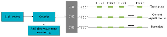
Figure 1.
Principle of fiber optic sensing-based monitoring.
The wavelength that can form periodic reflection through a Bragg grating is called the Bragg wavelength, and its central wavelength can be expressed as:
where is the Bragg wavelength, with a central wavelength range of 1515–1575 nm; is the effective refractive index; and is the grating period.
The relationship between the central wavelength shift of the fiber grating and strain can be expressed as:
In the formula, is the strain variation at the fiber core and kε is the strain sensitivity coefficient, which is influenced by factors such as the type and thickness of the protective coating material [37,38]. For bare optical fibers, the wavelength sensitivity of the fiber grating at 1550 nm is 1.2 pm/με.
The relationship between the center wavelength shift of the fiber grating and temperature can be expressed as:
In the formula, is the temperature change and is called the temperature sensitivity coefficient [39] (10 pm/°C is used in this experiment).
In summary, the relationship between the Bragg wavelength of single-mode silica fiber and strain change is:
2.2. Specimen Design and Fabrication
Figure 2 shows the typical structural configuration of a CRTS II slab ballastless track system, including the track slab, CA mortar layer, and concrete base slab. This three-layer arrangement corresponds to the structural system reproduced in the scaled specimens used in this study.
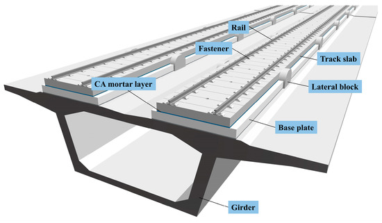
Figure 2.
Geometry of a typical CRTS II slab ballastless track system.
This test simulates the working condition of a high-speed railway on a bridge. After a 1:3 scale reduction, the dimensions of the track slab, CA mortar layer, and base plate are 1400 × 1000 × 70 mm, 1000 × 850 × 30 mm, and 1300 × 1200 × 100 mm, respectively. The concrete strength grades of the base plate and track slab are C40 and C60, with the mix proportions listed in Table 1.

Table 1.
Concrete ratio of base slab and track slab.
Two scaled CRTS II slab specimens were fabricated for this study. The only variable parameter between the two slabs was the diameter of the vertical reinforcement embedded through the three-layer system while all other materials, casting procedures, curing conditions, and sensor layouts were kept strictly identical. This design enables a controlled comparison of interlayer mechanical behaviour under different reinforcement configurations.
The CA mortar layer was prepared using a mixture of dry and wet components. Following the preparation principles reported by Feng et al. [40] and adapted through preliminary trials, the final composition included 52.5 ordinary Portland cement (606 g), coarse sand (363.6 g), fine sand (545.4 g), a water-reducing agent (12.125 g), aluminium powder (0.06 g), tap water (100 g), an emulsifier (91 g), an asphalt emulsion (303 g), a thickener (1.213 g), a defoamer (5 g), and 2–3 drops of concentrated hydrochloric acid. Due to the large number of components and their different dosages, two weighing scales of different capacities were used during batching to ensure measurement accuracy. The asphalt emulsion is highly sensitive to temperature—its solubility decreases and solid precipitation increases at low temperatures—so the mixing and casting of the CA mortar were conducted at relatively high temperatures to promote uniform dispersion and to ensure good forming quality. Similar CA mortar preparation details can be found in related CRTS II slab studies [7].
The two CRTS II slab specimens were denoted as CRTSII-A and CRTSII-B. Both slabs contained two vertical reinforcing bars passing through the track slab, CA mortar layer, and base plate, but with different bar diameters, as shown in Figure 3. This configuration was used to investigate the influence of reinforcement diameter on interlayer mechanical behaviour under vertical loading.
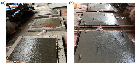
Figure 3.
Fabrication Diagram for Ballastless Track Type II Slab: (a) Preparation of CA Mortar Layer; and (b) Embedding of Vertical Reinforcing Bars.
A 1:3 geometric scale was adopted due to the practical constraints of full-scale CRTS II slab fabrication and testing. A full-scale slab requires an integrated casting bed, continuous pouring of the CA mortar layer, and the embedding of long quasi-distributed optical fiber arrays. Such specimens cannot be transported, installed, or vertically loaded using standard laboratory equipment. The 1:3 scale enables the three-layer structural configuration, reinforcement arrangement, and interlayer load-transfer characteristics to be reproduced while keeping the specimen size compatible with the capacity of the loading system. The scaled results should therefore be interpreted as representative structural trends and interlayer deformation mechanisms, rather than direct full-scale absolute values.
Although absolute force levels from the scaled specimens cannot be directly extrapolated to full-scale structures, the comparative behaviors examined in this study are governed primarily by geometric compatibility, stiffness ratios, and interlayer load-transfer mechanisms, which are preserved under the adopted scale. The deformation coordination between the track slab, CA mortar layer, and base plate is governed primarily by geometric compatibility, stiffness ratios, and the load-transfer mechanism across the three layers. These governing relationships are preserved under geometric scaling when the constituent materials, layer arrangement, reinforcement anchorage, and boundary conditions are reproduced consistently, as is the case in the present 1:3 specimens. Therefore, while the scaled tests do not represent the full-scale response in magnitude, they reliably capture the relative influence of reinforcement diameter on interlayer deformation and on the progression toward the ultimate state under identical loading procedures.
2.3. Sensor Embedding and Monitoring Point Layout
Two types of quasi-distributed FBG sensors were used in this experiment. The first type consisted of commercially manufactured FBG sensors with pre-attached patch cords. The second type consisted of bare-fiber FBGs fabricated in the laboratory through coating removal, fiber end-face cleaving, fusion splicing, and heat-shrink protection. Before installation, all sensors were connected to the interrogator to verify signal continuity and wavelength stability. Sensors that did not meet the required sensitivity or baseline conditions were replaced.
For the track slab and the base slab, sensors were embedded inside the reinforcement. A groove was cut along the surface of the steel bar to accommodate the optical fiber. The groove dimensions were approximately 5 to 6 mm in width and 5 to 6 mm in depth. After the sensor was placed in the groove, a two-component epoxy resin, mixed at a mass ratio of 2:1 (resin to hardener), was applied to fully encapsulate the fiber. The epoxy was allowed to cure for 24 h at a temperature of 20 to 25 °C. The effective bonding length between the optical fiber and the steel–concrete interface was greater than 120 mm, which ensured stable strain transfer. At each sensor position, a strain gauge was installed on the opposite side of the reinforcement after grinding the surface smooth, in order to compare the performance of optical fiber sensing with conventional electrical measurement, as shown in Figure 4a.
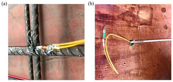
Figure 4.
Adhesion of strain gauge: (a) Adhesion of strain gauge and (b) Fiber buried in PVC pipe.
In the CA mortar layer, where reinforcement is not present, five FBG sensors were embedded as monitoring points. Each sensing element was placed inside a PVC conduit with an inner diameter of 6 mm and a wall thickness of 1 mm. After positioning the conduit in the designed groove, a thin layer of epoxy resin was applied to secure and protect the fiber. The minimum bending radius of the optical fiber was maintained at more than 30 mm to avoid micro-bending losses, as illustrated in Figure 4b. After casting of the CA mortar layer, all sensors were checked once again to confirm that the monitoring system remained functional.
To establish a clear correspondence between the sensing locations and the strain measurements reported later in this paper, the naming and arrangement of all monitoring points are summarized in Figure 5. As shown in the figure, the reinforcement-based sensing points in the track slab are labeled T1-R1, T1-R2, and T1-R3, indicating the three FBG positions embedded within the reinforcement of the first track slab. The monitoring points within the CA mortar layer are labeled C1-R1 to C1-R5, corresponding to the five vertically aligned FBG sensors embedded inside the PVC conduits. The sensing points in the base plate are labeled B1-R1, B1-R2, and B1-R3, following the same reinforcement-embedded layout as the track slab. These identifiers are used consistently in the subsequent figures and discussions to ensure unambiguous interpretation of the load–strain responses.
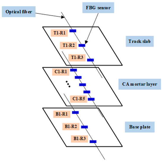
Figure 5.
Installation scheme and naming of FBG monitoring points in the track slab, CA mortar layer, and base plate.
In this study, the electrical strain gauges used on the reinforcement had a gauge length of 10 mm and a sensitivity coefficient of 2.08. The FBG sensors exhibited a wavelength sensitivity of 1.2 pm/με for strain and 10 pm/°C for temperature, with an effective bonding length greater than 120 mm and epoxy encapsulation following the procedures described in Section 2.3. The optical interrogation unit operated within the 1515–1575 nm range, and the data acquisition frequency was 10–100 Hz for the FBG system and 2 Hz for the electrical strain gauges.
2.4. Experiment Loading and Data Collection
Using a multifunctional structural experimental system, as shown in Figure 6, with a maximum thrust of 10,000 kN, a maximum tension of 3000 kN, and a stroke of ±300 mm, a vertical load is applied by controlling the hydraulic oil source. Strain data and fiber optic data are collected through the data acquisition system, and finally, the test specimen is installed and fixed.
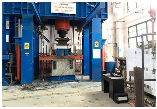
Figure 6.
Multifunctional structure experiment system.
The loading method adopts load control, starting with preloading to check the working status of each sensor, data storage, and specimen fixation. After eliminating any abnormalities, the formal experimental loading begins. The vertical load is applied in increments of 200 kN; after reaching the target value, the pressure is maintained for 1 min while recording experimental phenomena and storing data. Then the load is unloaded and the next level of load is applied, continuing until the specimen fails and the experiment ends.
Under vertical loading, the primary failure modes of the CRTS II slab system included bending of the vertical reinforcement, cracking of the track slab, and crushing of the CA mortar layer. These phenomena developed in the same sequence in both tested specimens. Figure 7 shows the representative failure appearance of specimen CRTSII-A, where bending of the vertical reinforcement led to local spalling of the concrete in the track slab, and the CA mortar layer exhibited surface crushing near the loading region [7]. The same failure patterns were observed in specimen CRTSII-B, with only minor differences in the load level at which each stage initiated.
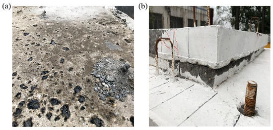
Figure 7.
Main damage phenomena under vertical loading: (a) Bending of vertical reinforcement and (b) CA mortar layer crushing.
To clarify the scope of the experimental program, two specimens with different vertical-reinforcement diameters were tested in this study. This design follows established practice in CRTS II slab-track physical modelling, where specimen dimensions, integrated CA-mortar casting, and embedded quasi-distributed optical fibers make large-batch repetitive testing impractical. The two specimens were produced in a continuous casting sequence using the same material batches and curing conditions, and the loading system, boundary conditions, and sensor layouts were kept strictly identical. The observed differences in mechanical response therefore reflect the influence of reinforcement diameter under controlled experimental conditions rather than statistical variation.
3. Comparison Between Fiber Optic Sensing-Based Monitoring and Traditional Monitoring
In this section, the strain responses obtained by fiber optic sensing and by conventional electrical strain gauges are compared for the track slab. Figure 8 and Figure 9 show the load–strain curves of the embedded longitudinal reinforcement in the lower part of the track slab under vertical loading. Figure 8 presents the axial strain recorded by the FBG sensors, whereas Figure 8 presents the axial strain recorded by the electrical strain gauges installed at the corresponding reinforcement locations.
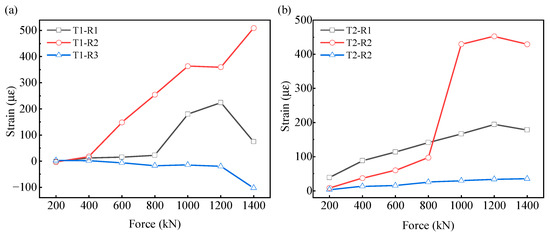
Figure 8.
Load-strain curve of track plate under fiber optic sensing-based monitoring: (a) Track plate 1 and (b) Track plate 2.
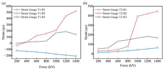
Figure 9.
Load-strain curve of track plate under conventional monitoring: (a) Track plate 1 and (b) Track plate 2.
Comparing Figure 8a with Figure 9a and Figure 8b with Figure 9b, it can be seen that the load-strain curves of the same track slab under the two monitoring methods are similar, which also indicates the accuracy of the monitoring data from these two methods. The traditional monitoring method is suitable for reinforced concrete structures, where strain gauges are embedded at a certain position of the rebar within the concrete to monitor the strain of the rebar and concrete at that location. Strain gauges are attached to the opposite side of the rebar at the fiber optic monitoring points on the track slab and base slab. By comparing Figure 8 and Figure 9, the differences between the traditional monitoring and fiber optic sensing-based monitoring can be summarized as follows:
- In Figure 8, the initial strain monitored by the optical fiber sensor is around 0, while in Figure 9, the strain gauge shows a relatively large initial strain, indicating that both monitoring methods are affected by environmental noise. However, the optical fiber sensor monitoring is less affected, with a smaller initial strain that is closer to the actual monitoring conditions.
- In Figure 9a, the initial strain of strain gauge 3 is −133 με, which severely affects the load-strain curve of strain gauge 3, resulting in relatively large negative strain values at this measurement point under different loads. Under traditional monitoring, a large initial strain causes the measured strain values during loading to be overestimated, leading to distortion of the monitoring results; fiber optic sensing-based monitoring can reduce the impact of initial strain on the monitoring results.
- The strain conditions reflected in Figure 8b and Figure 9b are basically similar. In most cases, the strain values at measurement points 1 and 3 are less than that at measurement point 2, indicating greater deformation at the center point of the mid-span. Both monitoring methods can identify the measurement point with the maximum strain. The data acquisition frequencies of the two monitoring methods differ: fiber optic sensing-based monitoring can achieve 10 to 100 measurements per second, whereas traditional monitoring is generally 2 measurements per second, and its measurement accuracy is much lower than that of fiber optics. Fiber optic sensing-based monitoring shows greater advantages in detecting small deformations.
The two monitoring methods show similar load-strain conditions in track plates 3 and 4 as well as the base plate, so they will not be elaborated here. In addition to advantages such as high monitoring accuracy and strong resistance to noise interference, fiber optic sensing-based monitoring is also more flexible and has a wider range of applications, which is one of the reasons it can be widely used in various monitoring tasks. In this experiment, the main components of the CA mortar layer are asphalt, sand, concrete, and various admixtures. After preparation, it has relatively high fluidity and mainly serves a cushioning function. No reinforcement bars are arranged inside it, whereas traditional monitoring methods require adhesive carriers, making internal monitoring impossible. Fiber optic sensing-based monitoring can solve the monitoring challenges of traditional methods.
4. Load–Strain Response of Track Slabs Based on Multi-Source Monitoring
Under vertical loading, the cross-sectional strain responses of the CA mortar layer in the four slabs are shown in Figure 10. The CA mortar layer is the most flexible component of the three-layer CRTS II system. Positioned between the track slab and the base slab, it accommodates differential deformation, absorbs part of the applied energy, and contributes to vibration isolation. When vertical loads are transmitted from the track slab to the mortar layer, its lower stiffness results in measurable deformation governed jointly by material heterogeneity and reinforcement configuration.
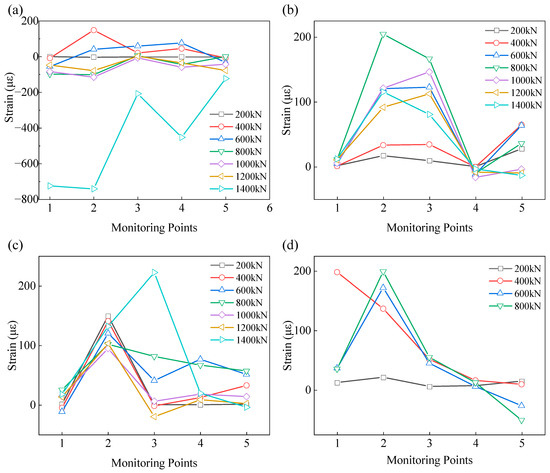
Figure 10.
Strain curve of CA mortar layer section under vertical load (a) CA mortar layer 1; (b) CA mortar layer 2; (c) CA mortar layer 3; and (d) CA mortar layer 4.
As clarified in Section 2, the 1:3 geometric scale reproduces the structural load-transfer mechanism of the three-layer system while ensuring compatibility with laboratory loading facilities.
The quasi-distributed optical fiber sensors recorded the strain development within the CA mortar layer at multiple depths and lateral positions. The key observations from Figure 9 are summarized below.
- (1)
- In Figure 9b and Figure 10a,d, the CA mortar layer remains in an elastic state under a 200 kN load, with all five monitoring points exhibiting small and nearly uniform strains. In contrast, Figure 10c shows a maximum strain of approximately 150 με at the same load level, indicating the presence of local nonuniformity in the mortar microstructure. This behavior is consistent with the known influence of asphalt-rich phases on the homogeneity of CA mortar.
- (2)
- At all monitoring points, strain increases progressively with load and is primarily tensile at early stages. The maximum tensile strain reaches approximately 200 με. In Figure 9a, when the load approaches 1400 kN, the strain switches abruptly from tension to compression, accompanied by visible crushing of the CA mortar. This indicates that the reinforced mortar layer reaches its ultimate compressive state at this load level, with a corresponding ultimate capacity of about 1400 kN.
- (3)
- The load levels associated with the peak tensile strain in CA mortar layers 1, 2, and 3 increase sequentially—approximately 400 kN, 800 kN, and 1400 kN. This progression demonstrates that larger-diameter vertical reinforcement more effectively restrains mortar deformation. As the CA mortar and the vertical rebars deform cooperatively, the compressive load-bearing capacity is enhanced and the onset of compressive failure is delayed.
- (4)
- In Figure 10d, the CA mortar layer without vertical reinforcement shows limited capacity to resist vertical deformation. At a load of around 400 kN, strain approaches its maximum, followed by a marked decrease in compressive resistance. The ultimate load of this unreinforced configuration is about 800 kN. The absence of restraint causes deformation to concentrate directly within the mortar, thereby reducing overall load-transfer efficiency. Comparison across the four configurations confirms that the presence—and particularly the diameter—of vertical reinforcement is the dominant factor governing the compressive behavior of the CA mortar layer.
Based on the multi-point optical fiber measurements, the quasi-distributed sensing system effectively captures the spatial distribution and progression of strain within the CA mortar layer. Although the number of specimens is limited, the consistent deformation trends observed across different reinforcement configurations, together with the agreement between optical fiber readings and conventional strain gauges, support the reliability of the identified interlayer mechanisms. Integrating the initial strain level, the tensile-to-compressive transition, and the ultimate capacity provides a robust basis for evaluating the damage evolution of the CA mortar layer, which is relevant to long-term performance assessment of CRTS II ballastless track systems.
5. Conclusions
This study employed quasi-distributed fiber optic sensing technology to analyze the stress characteristics of the CA mortar layer in Type II slabs for ballastless track systems, yielding the following conclusions:
- Fiber optic sensing-based monitoring offers a broader range of applicability and higher precision compared to traditional monitoring methods, making it well-suited for monitoring tasks involving special subjects such as asphalt and mortar deformation.
- The strain response of CA mortar layers under vertical loading exhibits significant non-uniformity, with internal deformation influenced by both material homogeneity and load levels.
- The ultimate load capacity of CA mortar layers reinforced with vertical steel bars is 1400 kN, representing a 75% increase in load-bearing capacity compared to unreinforced CA mortar layers. The vertical steel bars restrict deformation of the CA mortar layer, thereby enhancing compressive load-bearing capacity and improving the structure’s overall coordinated deformation capability.
In summary, the adoption of quasi-distributed fiber optic sensing technology can meet the stress monitoring requirements for ballastless track Type II slabs. It effectively reflects the internal stress characteristics of the structure and satisfies the long-term monitoring demands, thereby providing a novel monitoring approach for investigating the internal stress failure mechanisms within ballastless track Type II slabs.
Author Contributions
Conceptualization, X.G.; Methodology, X.G.; Formal analysis, X.X. and L.W.; Investigation, X.X.; Resources, X.Z.; Data curation, X.Z. and L.W.; Writing—original draft, X.G.; Writing—review & editing, L.W. and P.X.; Project administration, P.X. All authors have read and agreed to the published version of the manuscript.
Funding
This study received funding from the Science and Technology Research and Development Program of China Railway Group Limited (Grant No. 2022-Major-14).
Institutional Review Board Statement
Not applicable.
Informed Consent Statement
Not applicable.
Data Availability Statement
The data presented in this study are available on request from the corresponding author. The data are not publicly available due to the presence of proprietary sensitive information obtained under a non-disclosure agreement.
Conflicts of Interest
Author Xiao Guo was employed by the company China Railway Engineering Design and Consulting Group Co., Ltd. and China Railway Group Limited. The remaining authors declare that the research was conducted in the absence of any commercial or financial relationships that could be construed as a potential conflict of interest. The authors declare that this study received funding from Science and Technology Research and Development Program of China Railway Group Limited. The funders were not involved in the study design, data collection, data analysis, interpretation of results, the writing of the manuscript, or the decision to submit it for publication.
References
- Zhang, X.; Xie, X.; Tang, S.; Zhao, H.; Shi, X.; Wang, L.; Wu, H.; Xiang, P. High-Speed Railway Seismic Response Prediction Using CNN-LSTM Hybrid Neural Network. J. Civil Struct. Health Monit. 2024, 14, 1125–1139. [Google Scholar] [CrossRef]
- Zhao, H.; Wei, B.; Jiang, L.; Xiang, P.; Zhang, X.; Ma, H.; Xu, S.; Wang, L.; Wu, H.; Xie, X. A Velocity-Related Running Safety Assessment Index in Seismic Design for Railway Bridge. Mech. Syst. Signal Process. 2023, 198, 110305. [Google Scholar] [CrossRef]
- Wei, B.; Chen, M.; Jiang, L.; Li, C.; Chen, Y.; Lu, A.; Yang, Z.; Li, S. The Influence of Spherical Bridge Bearings on Train Running Safety during Earthquakes Considering Train-Track–Bridge Interaction and Soil Specification. Arch. Civ. Mech. Eng. 2025, 25, 143. [Google Scholar] [CrossRef]
- Liu, L.; Jiang, L.; Zhou, W.; Liu, X.; Feng, Y. Analysis of Seismic Damage Features of HSR CRTS III SBT Simply Supported Bridge System. Archiv. Civ. Mech. Eng. 2023, 23, 76. [Google Scholar] [CrossRef]
- Peng, X.; Liu, Z.; Zhang, P.; Chen, Y.; Shao, Z.; Zhao, H.; Xie, X.; Jiang, L.; Huang, Z.; Pan, Z.; et al. Adaptable Graph Region for Optimizing Performance in Dynamic System Long-Term Forecasting via Time-Aware Expert. Nat. Commun. 2025, 16, 10213. [Google Scholar] [CrossRef] [PubMed]
- Zhang, X.; Wang, J.; Chen, Z.; Quan, Y.; Zheng, Z.; Zhang, T.; Cao, J.; Xie, X.; Liu, X.; Xiang, P. A Distributed Fiber Optic Sensor-Based Approach for Crack Asphalt Structure under Freeze-Thaw Cycling Tests. Constr. Build. Mater. 2025, 476, 141262. [Google Scholar] [CrossRef]
- Zhang, X.; Wang, L.; Tang, S.; Cui, H.; Xie, X.; Wu, H.; Liu, X.; Yang, D.; Wang, H.; Xiang, P. Investigations on the Shearing Performance of Ballastless CRTS II Slab Based on Quasi-Distributed Optical Fiber Sensing. Opt. Fiber Technol. 2023, 75, 103129. [Google Scholar] [CrossRef]
- Gautier, P.-E. Slab Track: Review of Existing Systems and Optimization Potentials Including Very High Speed. Constr. Build. Mater. 2015, 92, 9–15. [Google Scholar] [CrossRef]
- Zhai, W.; Han, Z.; Chen, Z.; Ling, L.; Zhu, S. Train–Track–Bridge Dynamic Interaction: A State-of-the-Art Review. Veh. Syst. Dyn. 2019, 57, 984–1027. [Google Scholar] [CrossRef]
- Zheng, X.; Wei, B.; Jiang, L.; Lai, Z.; Chen, J.; Chen, M.; Xiao, B.; Zhang, R.; Yang, Z. Active Learning-Based Regional Seismic Risk Assessment of High-Speed Railway Bridges. Adv. Eng. Inform. 2025, 66, 103470. [Google Scholar] [CrossRef]
- Xiao, B.; Wei, B.; Zhao, X.; Wang, W.; Pang, L.; Jiang, L.; Yang, Z.; Zheng, X.; Zhang, R. Response Analysis of High-Speed Railway Isolation Bridge under near-Fault Earthquake: Refined Modeling Method of Co-Simulation and Full-Bridge Shaking Table Test. Soil Dyn. Earthq. Eng. 2026, 200, 109807. [Google Scholar] [CrossRef]
- Wei, B.; Zhang, R.; Jiang, L.; Zheng, X.; Ji, W.; Ma, G. Scale Model Test and Numerical Analysis on the Anchorage Zone of a Cable-Stayed Bridge with the Cross-Anchor Structure. Eng. Struct. 2024, 316, 118614. [Google Scholar] [CrossRef]
- Zhou, R.; Zhu, X.; Ren, W.-X.; Zhou, Z.; Yao, G.; Ma, C.; Du, Y. Thermal Evolution of CRTS II Slab Track under Various Environmental Temperatures: Experimental Study. Constr. Build. Mater. 2022, 325, 126699. [Google Scholar] [CrossRef]
- Cui, X.; Xiao, H. Interface Mechanical Properties and Damage Behavior of CRTS II Slab Track Considering Differential Subgrade Settlement. KSCE J. Civ. Eng. 2021, 25, 2036–2045. [Google Scholar] [CrossRef]
- Li, Y.; Chen, J.; Wang, J.; Shi, X.; Chen, L. Study on the Interface Damage of CRTS II Slab Track under Temperature Load. Structures 2020, 26, 224–236. [Google Scholar] [CrossRef]
- Zhou, R.; Zhu, X.; Du, Y.; Ma, C.; Liu, W.; Ren, W.; Zhang, L. Thermal Response of the Bridge Supported Longitudinal CRTS II Slab Track Subject to Diurnal Temperature Variation. Constr. Build. Mater. 2023, 395, 132332. [Google Scholar] [CrossRef]
- Xu, Q.; Sun, S.; Xu, Y.; Hu, C.; Chen, W.; Xu, L. Influence of Temperature Gradient of Slab Track on the Dynamic Responses of the Train-CRTS III Slab Track on Subgrade Nonlinear Coupled System. Sci. Rep. 2022, 12, 14638. [Google Scholar] [CrossRef]
- Xia, Q.; Chen, B.; Tan, J.; Zhang, X.; Xiang, P. Dynamic Analysis of Laminated Plate and Ballastless Track Slab on Pasternak Foundation under Moving Load Based on Different Shear Deformation Theory. Mech. Based Des. Struct. Mach. 2025, 53, 2182–2214. [Google Scholar] [CrossRef]
- Rutherford, T.; Wang, Z.; Shu, X.; Huang, B.; Clarke, D. Laboratory Investigation into Mechanical Properties of Cement Emulsified Asphalt Mortar. Constr. Build. Mater. 2014, 65, 76–83. [Google Scholar] [CrossRef]
- Wang, Z.; Shu, X.; Rutherford, T.; Huang, B.; Clarke, D. Effects of Asphalt Emulsion on Properties of Fresh Cement Emulsified Asphalt Mortar. Constr. Build. Mater. 2015, 75, 25–30. [Google Scholar] [CrossRef]
- Zhang, H.; Wang, Z.; Wang, Q. Quantitative Evaluation of Cement Emulsified Asphalt Mortar and Aggregate Adhesion Performance with Dynamic Mechanical Analysis. Constr. Build. Mater. 2020, 262, 120043. [Google Scholar] [CrossRef]
- Liu, Y.; Kong, X.; Zhang, Y.; Yan, P. Static and Dynamic Mechanical Properties of Cement-Asphalt Composites. J. Mater. Civ. Eng. 2013, 25, 1489–1497. [Google Scholar] [CrossRef]
- Zhu, H.; Zeng, X.; Lan, X.; Song, H.; Long, G.; Xie, Y. Effects of High Temperature on Creep Properties of Cement and Emulsified Asphalt Mortar. J. Mater. Civ. Eng. 2022, 34, 04022128. [Google Scholar] [CrossRef]
- Hu, H.; Xiang, P.; Zhao, H.; Zeng, Y.; Zhang, P.; Shao, Z.; Xie, X.; Jiang, L. A Chebyshev Interval Computational Framework for Propagating Parameter Uncertainty in Train-Track-Bridge Systems. Adv. Eng. Softw. 2025, 204, 103884. [Google Scholar] [CrossRef]
- Yang, Y.-B.; Wu, Y.-S. DYNAMIC STABILITY OF TRAINS MOVING OVER BRIDGES SHAKEN BY EARTHQUAKES. J. Sound Vib. 2002, 258, 65–94. [Google Scholar] [CrossRef]
- Xu, L.; Zhai, W. Vehicle–Track–Tunnel Dynamic Interaction: A Finite/Infinite Element Modelling Method. Rail. Eng. Sci. 2021, 29, 109–126. [Google Scholar] [CrossRef]
- Xia, H.; Han, Y.; Zhang, N.; Guo, W. Dynamic Analysis of Train–Bridge System Subjected to Non-Uniform Seismic Excitations. Earthq. Eng. Struct. Dyn. 2006, 35, 1563–1579. [Google Scholar] [CrossRef]
- Chen, J.; Wei, B.; Xiao, B.; Chen, M.; Zheng, X.; Yang, Z.; Jiang, L. Evaluation of the Anti-Collision Performance of Reinforced Concrete Protective Wall for Railway Bridges under High-Speed Train Impact. Eng. Fail. Anal. 2025, 182, 110097. [Google Scholar] [CrossRef]
- Chen, J.; Wei, B.; Jiang, L.; Zheng, X.; Yuan, S.; Chen, M. Optimization Design and Simplified Model of a Multi-Layered Nested Tubular Structure for Train Collision Protection. Adv. Eng. Softw. 2025, 211, 104039. [Google Scholar] [CrossRef]
- Sun, S.; Xu, Q.; Wang, X.; Fan, H.; Xu, Y.; Zhang, Z. Time-Varying Temperature Field and Thermal Effect of CRTS III Slab Track Structure in Curved Sections under Natural Environmental Temperature. Therm. Sci. Eng. Prog. 2025, 57, 103130. [Google Scholar] [CrossRef]
- Xu, Y.; Liu, H.; Xie, R.; Chen, Y.; Guo, D.; Chen, S. In-Situ Investigation of Interlayer Interface Bonding Defect-Formation Mechanisms during FRAM. Int. J. Mech. Sci. 2025, 299, 110406. [Google Scholar] [CrossRef]
- Leung, C.K.Y.; Wan, K.T.; Inaudi, D.; Bao, X.; Habel, W.; Zhou, Z.; Ou, J.; Ghandehari, M.; Wu, H.C.; Imai, M. Review: Optical Fiber Sensors for Civil Engineering Applications. Mater Struct 2015, 48, 871–906. [Google Scholar] [CrossRef]
- Zhang, X.; Liu, L.; Zheng, Z.; Quan, Y.; Chen, Z.; Cao, J.; Zhang, T.; Xie, X.; Liu, X.; Xiang, P. Bending Strain Progression and Damage of Asphalt Beams Based on Distributed Fibre Optic Sensors. Int. J. Pavement Eng. 2025, 26, 2479645. [Google Scholar] [CrossRef]
- Sasy Chan, Y.W.; Tantely, J.S.; Wang, H.; Wang, Z.; Jiang, H.; Zhou, Z. Compressive Behavior and Self-Sensing Performance of BFRP-Strengthened Short Circular Hollow Section Stocky Steel Tubes with Embedded FBG Sensors. Structures 2025, 80, 110041. [Google Scholar] [CrossRef]
- Liang, M.; Chen, N.; Fang, X.; Wu, G. Strain Transferring Mechanism Analysis of the Surface-Bonded FBG Sensor. Appl. Opt. 2018, 57, 5837. [Google Scholar] [CrossRef] [PubMed]
- Wang, H.; Wu, Y.; Chen, C.; Guo, Y. In-Site Health Monitoring of Cement Concrete Pavements Based on Optical Fiber Sensing Technology. J. Road Eng. 2023, 3, 113–123. [Google Scholar] [CrossRef]
- Barrias, A.; Casas, J.; Villalba, S. A Review of Distributed Optical Fiber Sensors for Civil Engineering Applications. Sensors 2016, 16, 748. [Google Scholar] [CrossRef]
- Bado, M.F.; Casas, J.R. A Review of Recent Distributed Optical Fiber Sensors Applications for Civil Engineering Structural Health Monitoring. Sensors 2021, 21, 1818. [Google Scholar] [CrossRef]
- Rodsin, K.; Ejaz, A.; Wang, H.; Saingam, P.; Joyklad, P.; Khaliq, W.; Hussain, Q.; Boonmee, C. Machine Learning and Regression Models for Evaluating Ultimate Performance of Cotton Rope-Confined Recycled Aggregate Concrete. Buildings 2024, 15, 64. [Google Scholar] [CrossRef]
- Feng, Y.; Jiang, L.; Zhou, W.; Han, J.; Zhang, Y.; Nie, L.; Tan, Z.; Liu, X. Experimental Investigation on Shear Steel Bars in CRTS II Slab Ballastless Track under Low-Cyclic Reciprocating Load. Constr. Build. Mater. 2020, 255, 119425. [Google Scholar] [CrossRef]
Disclaimer/Publisher’s Note: The statements, opinions and data contained in all publications are solely those of the individual author(s) and contributor(s) and not of MDPI and/or the editor(s). MDPI and/or the editor(s) disclaim responsibility for any injury to people or property resulting from any ideas, methods, instructions or products referred to in the content. |
© 2025 by the authors. Licensee MDPI, Basel, Switzerland. This article is an open access article distributed under the terms and conditions of the Creative Commons Attribution (CC BY) license (https://creativecommons.org/licenses/by/4.0/).