Featured Application
This paper demonstrates an AI-driven teaching-based robotic arm for smart food processing, enabling pattern recognition and automation without complex programming.
Abstract
Teaching-based robotic systems offer an accessible alternative to complex inverse kinematics programming for food processing automation. Traditional model-based approaches require precise system identification and analytical solutions that are challenging for custom-built robots with manufacturing tolerances and mechanical uncertainties. This study developed a custom six-degree-of-freedom robotic arm using modular brushless motors controlled via Controller Area Network communication and Robot Operating System 2, a teaching mode where users manually demonstrate trajectories that are recorded at 100 Hz. Forty-five demonstration trajectories were collected across three geometric patterns (rectangle, triangle, circle) and augmented to 270 samples. A bidirectional Long Short-Term Memory network with attention mechanism was trained to classify patterns, achieving 83.33% test accuracy and outperforming baseline deep learning models (1D-CNN: 77.78%, TCN: 66.67%, GRU: 44.44%), while being marginally exceeded by Random Forest (86.11%). Rectangle patterns showed strongest recognition (78.57% F1-score), while circle patterns achieved highest performance (91.67% F1-score). However, severe overfitting was observed, with validation accuracy peaking at 85.19% at epoch 24 before degradation, indicating insufficient dataset size despite five-fold augmentation. The results demonstrate proof-of-concept feasibility for pattern recognition from limited teaching demonstrations, providing a pathway for robotic food processing without extensive programming expertise, though larger datasets and robust feedback control strategies are required for production deployment.
1. Introduction
The ongoing Fourth Industrial Revolution, commonly referred to as Industry 4.0 or 4IR, represents an industrial transformation that emphasizes automation, interconnectivity, and real-time process optimization through the integration of digital technologies such as the Internet of Things (IoT), machine learning (ML), artificial intelligence (AI), cyber physical systems (CPS), cloud computing, additive manufacturing (AM), digital twins, and robotics [1,2,3,4,5]. In the Industry 4.0 environment, automation and robotics perform complex, hazardous, and repetitive tasks in place of human workers, thereby achieving continuous 24-h production with enhanced efficiency and reliability [6]. These automation technologies have been increasingly adopted in food processing industries [7,8,9], where robotic systems handle tasks ranging from material handling and packaging to precision decoration and quality inspection. Furthermore, these systems undertake intelligent operations including material handling, data acquisition, monitoring, and customer service, and have emerged as pivotal components that manage assembly lines and overall manufacturing processes through integration with various digital technologies [10]. At the heart of this industrial transformation lies the robot manipulator, which serves as the most ubiquitous yet essential automation equipment [11]. Robot manipulators with multi-joint architectures perform precision tasks such as assembly, welding, and pick-and-place operations, ensuring flexibility and productivity [12,13]. Consequently, precise control technology that enables rapid and accurate movement of the manipulator’s end-effector to desired positions and orientations constitutes the most fundamental prerequisite for all robotic applications [14]. In particular, the ability to control the end-effector trajectory in Cartesian coordinates is essential. The core of this precision control lies in solving the inverse kinematics (IK) problem [15]. Kinematics refers to the field that analytically studies the motion of robot manipulators and is broadly divided into forward kinematics (FK) and IK. A schematic representation of FK and IK is illustrated in Figure 1.
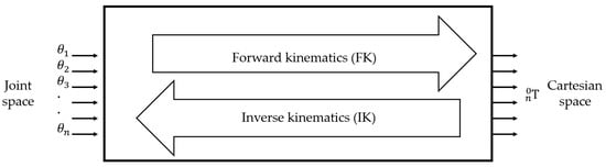
Figure 1.
Transformation between joint space and Cartesian space: forward kinematics (FK) computes end-effector pose from joint angles, while inverse kinematics (IK) determines joint angles from desired end-effector pose.
Forward kinematics involves calculating the position and orientation of the end-effector from joint variables; this problem is generally straightforward and always yields a solution. Inverse kinematics, on the other hand, involves computing joint angles from the desired position and orientation of the end-effector. This problem may have multiple solutions for a single target point or no solution at all, and the calculations are highly complex due to the nonlinear structure of robots. Numerous researchers have conducted in-depth studies on IK in robotics [16]. The primary approaches to solving IK include analytical methods, algebraic methods, geometric methods, and numerical methods [17,18,19,20]. Pieper proposed that a six-degree-of-freedom (6-DOF) robot with three consecutive intersecting joint axes at a single point possesses an analytical solution. His design solution is known as Pieper’s criterion [21]. In 1986, Primrose first provided conclusive evidence based on the literature that the IK problem for a general 6-DOF robot has a maximum of 16 real solutions [22]. Liao et al. [23] obtained 16 sets of IK solutions using the unitary matrix method. Subsequently, Lee [24] employed vector theory, and Raghavan and Roth [25] achieved identical results using the dialytic elimination method. However, these analytical methods have limitations in practical industrial applications due to their complex mathematical derivation processes and high computational complexity. To address these challenges, machine learning-based IK solutions have recently emerged as promising alternatives. These methods demonstrate the potential to solve inverse kinematics problems through learning from input–output data without requiring mathematical modeling. Köker et al. employed neural networks to solve the inverse kinematics of a three-joint robot [26]. The designed neural network successfully provided correct joint angles corresponding to given Cartesian coordinates. Köker utilized a combination of neural networks and genetic algorithms to solve the inverse kinematics of the Stanford robot manipulator [27]. The designed hybrid system successfully achieved micrometer-level errors by improving the precision of conventional neural network results to ten significant figures. Csiszar et al. employed neural networks to solve the inverse kinematics problems of two-degree-of-freedom (2-DOF) and three-degree-of-freedom (3-DOF) robot manipulators [28]. The proposed neural network achieved positional errors below 0.1 mm for more than 99% of the validation data, even in models with assembly errors, demonstrating the potential to secure the precision required for industrial robots without separate calibration procedures. Hasan et al. proposed an artificial neural network-based adaptive learning strategy that does not require prior kinematic model knowledge for controlling 6-DOF manipulators [29]. This approach demonstrated the advantage of flexibly adapting to changes in the robot’s physical configuration. Lu et al. employed a joint space partitioning strategy and a numerical error minimization-based neural network approach to solve the inverse kinematics problem of a six-axis robot manipulator [30]. The designed multilayer perceptron networks successfully achieved enhanced efficiency and accuracy compared to conventional neural network methods through adaptive selection via a classification model and prediction error minimization. However, most existing ML-based IK studies are limited by their reliance on either idealized simulation data or data collected through precision measurement equipment. In actual robot systems, discrepancies arise between theoretical kinematic models and actual behavior due to factors such as assembly errors, reducer backlash, link flexibility, and variations in motor response characteristics. Furthermore, analytical IK methods have the disadvantage of difficult maintenance, as the entire mathematical model must be recalculated whenever the robot structure is modified or components are replaced.
As an alternative to address this limitation, teaching-based approaches have been proposed [31,32,33]. Learning from demonstration approaches have been extensively studied for robot programming, enabling non-experts to teach complex motions through physical guidance [31]. When users directly manipulate the robot to demonstrate desired trajectories, data that automatically incorporates all physical characteristics of the actual robot is collected during this process. By training ML models with such empirical data, precise trajectory reproduction becomes possible without complex kinematic modeling or calibration. This study aims to develop a teaching-based 6-DOF robotic arm system for precision food processing. Tasks such as cake decoration, chocolate garnishing, and 3D food printing frequently employ repetitive geometric patterns (straight lines, curves, circles, etc.); however, commercial industrial robots are costly and unsuitable for small-scale food manufacturing environments. Accordingly, this study developed a cost-effective robotic arm using modular brushless motors and established a real-time control system based on Controller Area Network (CAN) communication and Robot Operating System 2 (ROS 2) [34,35]. In particular, a system is proposed in which a machine learning model can automatically recognize and classify decoration patterns directly demonstrated by users. A classification model based on Bidirectional Long Short-Term Memory (BiLSTM) and attention mechanism was trained on representative geometric patterns (rectangles, triangles, circles), demonstrating the potential for pattern-based automatic decoration without complex inverse kinematics modeling. This study focused on the establishment of a hardware platform and proof of concept for the pattern recognition algorithm.
2. Materials and Methods
2.1. System Overview
The 6-DOF robotic arm developed in this study is driven by six brushless DC motors (Cubemars, Nanchang, China), each designed to provide the degrees of freedom necessary for the robotic arm to move in various directions and angles. The motors are powered by a 24 V DC power supply (RSP-2000-24, MEANWELL, New Taipei City, Taiwan). Motor communication is conducted via the CAN protocol. The CAN bus is a serial bus with a maximum bit rate of 1 Mbps and is well-known for its high reliability, real-time transmission capability, adaptability, and cost-effectiveness. It is widely used in various fields including industrial automation, automotive systems, and robotics [36]. The specifications of the motors used at each joint are presented in Table 1.

Table 1.
Specifications of brushless DC motors used in the robotic arm.
2.2. Mechanical Design and Fabrication
2.2.1. Kinematic Structure
The kinematic structure of the robotic arm was designed as a serial six-axis revolute joint (6R) configuration, with joint arrangements following a Z-X-Z-X-Z-X axis sequence. For the base joints (joints 1 and 2), AK80-64 motors with high gear reduction ratios (64:1) were deployed to secure sufficient torque to support the weight of the distal links. For the intermediate joints (joints 3 and 4), AK70-10 motors (10:1) were used, while lightweight AK60-6 motors (6:1) were positioned at the wrist joints (joints 5 and 6) to enable agility and precise control. Joint-wise motor assignments and ranges of motion are presented in Table 2.
Table 2.
Joint configuration and range of motion.
2.2.2. Link Design and Fabrication
The link structures of the robotic arm were designed in-house using Fusion 360 (Autodesk, San Francisco, CA, USA). Brackets and links for connecting each motor were designed, and the structure was configured to accommodate routing paths for power and CAN communication cables. The designed components were fabricated using a Fused Deposition Modeling (FDM) 3D printer (X1 Carbon, Bambu Lab, Shenzhen, China) with Polylactic Acid (PLA) filament (PLA Matte, Bambu Lab, Shenzhen, China), except for the base_link, which was printed using an Ender-3 V3 Plus (Creality, Shenzhen, China) to accommodate its larger dimensions beyond the Bambu Lab printer’s build volume. The printed components were assembled using M3, M4, and M5 bolts and nuts. Figure 2 shows the CAD model and fabricated robotic arm.
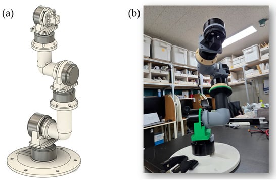
Figure 2.
(a) CAD model and (b) fabricated 6-DOF robotic arm using modular brushless motors and 3D-printed components.
2.2.3. End-Effector Design
A nozzle-type end-effector was designed and fabricated at the distal end of the robotic arm to dispense liquid or paste materials (Figure 3). The end-effector consists of a tube connector, nozzle body, and discharge outlet, and was fixed to joint 6 using bolted connections. The dispensing system was designed such that material supplied via external pneumatic pressure or a pump flows through a silicone tube (outer diameter: 8 mm, inner diameter: 5 mm) into the nozzle and is discharged through the outlet (diameter: 5 mm). The entire structure, including the end-effector, was designed using Fusion 360 and fabricated via 3D printing with PLA filament.
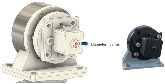
Figure 3.
End-effector design and fabricated component.
2.2.4. CAN Communication Hardware
Each motor is controlled via CAN bus communication at 1 Mbps. To secure communication bandwidth, the six motors were partitioned into three independent CAN buses, with two motors connected in a daisy chain configuration on each bus. Motors for joints 1–2, 3–4, and 5–6 were assigned to separate CAN buses, respectively. Each CAN bus is connected to the control PC through a USB-to-CAN adapter (CANable, Aideepen, Shenzhen, China), and 120 Ω termination resistors were installed at the last motor of each bus to prevent signal reflection. Motor interconnections were made using 4-pin CAN cables (A1257H-4P, Changjiang Connector, Shenzhen, China).
2.3. Software Implementation
2.3.1. CAN Communication Driver Implementation
A low-level driver for CAN communication was implemented directly in C++. To simultaneously manage three independent CAN buses, each interface was assigned a dedicated socket and read thread. During system initialization, the driver automatically detects available CAN interfaces, configures them to a 1 Mbps bitrate, and establishes connections.
Since the three types of motors used in the robotic arm (AK80-64, AK70-10, AK60-6) have different gear ratios and pole pair numbers, the specifications of each model were defined and an automatic mapping function was implemented for each motor ID. When transmitting control commands, velocity values in RPM are automatically converted to electrical RPM (ERPM) by considering each motor’s gear ratio and pole pair count. Received motor feedback is inversely converted to output shaft RPM for consistency.
Command transmission is performed at 10 ms intervals in a dedicated thread, with commands for each motor stored in a data structure. Data reception is continuously performed in independent threads for each CAN interface, and received motor status information is updated in real time. To improve efficiency, the driver automatically maps the source interface upon receiving the initial motor response and subsequently transmits commands only to that specific interface.
All CAN communication activities are logged in CSV format, including timestamps, data direction (transmission/reception), motor ID, and frame contents. This logging system enables detailed analysis when communication issues occur.
2.3.2. Robot Control System
The robot control system was implemented using the ros2_control framework, a modular architecture for real-time robot control in ROS 2 (Jazzy, Ubuntu 24.04). This framework separates hardware abstraction, controller logic, and system management into distinct layers, enabling flexible controller switching and standardized hardware interfaces.
At the hardware layer, a custom SystemInterface bridges the CAN communication driver with ros2_control. This interface handles bidirectional data flow: reading joint positions and velocities from motors (converted from degrees to radians) and transmitting position commands with velocity and acceleration limits via Position–Speed Loop control at 100 Hz.
The control layer employs two standard ros2_controllers: a joint state broadcaster publishing real-time joint data to ‘/joint_states’, and a joint trajectory controller executing motion commands from planning algorithms. Per-joint trajectory and goal tolerances are managed through YAML configuration files. The controller manager coordinates these components and handles lifecycle transitions. Figure 4 illustrates the overall system architecture, organized into four hierarchical layers. The Hardware Layer consists of CubeMars motors with integrated encoders, communicating via CAN bus at 1 Mbps. The Driver Layer implements the ros2_control hardware interface for motor control and state reading. The Control Layer contains the Controller Manager and Teaching Mode module. The Application Layer provides trajectory recording and BiLSTM+Attention pattern classification.
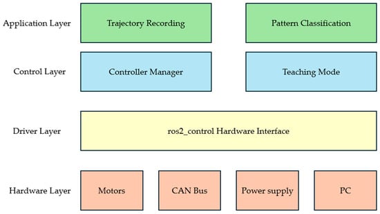
Figure 4.
Four-layer system architecture: Hardware Layer, Driver Layer, Control Layer, and Application Layer.
2.3.3. Homing Initialization
An automatic homing algorithm was implemented to establish the origin of each joint for precise position control. Using duty cycle control, the motors are driven at low speed, and the moment when the motor reaches its mechanical limit and stops is detected through velocity feedback. After detecting the limit, each joint moves by a predefined offset value to reach the actual zero position, which is then set as the origin. This process is performed sequentially for each joint and includes timeout and velocity threshold verification logic for safety.
2.3.4. Teaching Mode
A teaching mode was implemented that allows users to manually move the robotic arm to record trajectories. The robot’s kinematic structure was defined in a Unified Robot Description Format (URDF) file, specifying six revolute joints with their respective axes (Z-X-Z-X-Z-X configuration), joint limits, and link geometries. This URDF model enables automatic computation of forward kinematics via the ROS 2 tf2 library.
To facilitate consistent pattern demonstration, physical teaching guides were fabricated for the three geometric shapes (Figure 5). A 30 mm × 30 mm opening was created in the control box lid using a bolt hole guide template. Three pattern templates (rectangle, triangle, and circle) were designed in Fusion 360 and 3D-printed with PLA filament. Each template features bolt holes for secure attachment to the control box lid, providing a physical constraint that guides the end-effector along the desired trajectory during manual demonstration (Figure 6). The templates were affixed to the workspace surface using double-sided tape to prevent movement during teaching sessions.
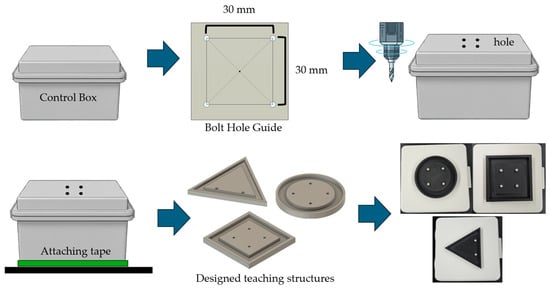
Figure 5.
Physical teaching guide fabrication process. A 30 mm × 30 mm opening was created in the control box lid, and pattern templates (rectangle, triangle, circle) were designed in Fusion 360 and 3D-printed for consistent trajectory demonstration.
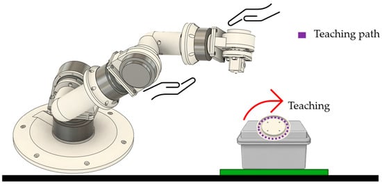
Figure 6.
Teaching mode demonstration showing manual manipulation of the robotic arm with the circular pattern template. The user guides the end-effector along the template path while kinematic data is recorded at 100 Hz.
Teaching mode is activated and deactivated via ROS 2 topic commands published to ‘/teaching_mode’ using the ‘std_msgs/msg/Bool’ message type. Publishing true initiates teaching mode, while publishing false terminates the mode and returns the robotic arm to its home position through trajectory planning. Figure 7 illustrates the complete teaching mode workflow.
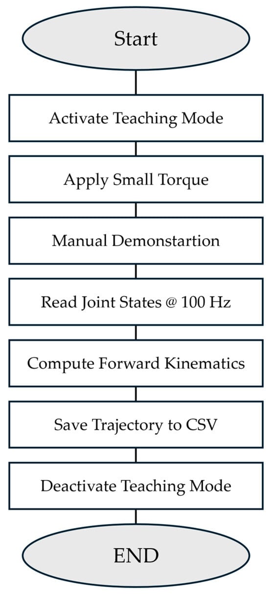
Figure 7.
Teaching mode workflow: ROS 2 service activation, gravity-compensated guidance, 100 Hz joint state recording, forward kinematics computation, and CSV export.
When teaching mode is activated, brake currents are applied to joints 3, 4, 5, and 6 (0.3 A, 0.3 A, 0.2 A, 0.15 A, respectively) to provide appropriate resistance, enabling users to move the robotic arm to desired positions while maintaining control. Joints 1 and 2, having high gear reduction ratios (64:1), retain sufficient inherent resistance without additional brake current. During this process, kinematic states from all joints are recorded in real time at 100 Hz to CSV files, including timestamps, frame numbers, joint angles (radians and degrees), joint velocities (RPM), motor currents (amperes), and end-effector Cartesian coordinates (x, y, z, roll, pitch, yaw). End-effector poses are computed by querying the transform from the base_link frame to the tcp (tool center point) frame using tf2, which performs real-time forward kinematics calculations based on the measured joint angles and the URDF kinematic model. The recorded trajectories serve as demonstration data for machine learning model training.
2.4. Pattern Recognition and Classification
2.4.1. Data Collection and Preprocessing
Demonstration data collected during teaching mode were initially stored in CSV format with timestamps, joint states (angular positions, velocities, and motor currents for all six joints), and end-effector Cartesian coordinates (x, y, z, roll, pitch, yaw). A preprocessing step was applied to remove the initial descent phase before the end-effector entered the working space. Trajectories were trimmed by detecting the first time point at which the z-coordinate descended below a threshold of 0.20 m, with an additional 10-frame buffer (0.1 s at 100 Hz sampling rate) retained before this point to capture approach dynamics. The original raw data were preserved with a “_raw.csv” suffix, and timestamps were reset to begin at zero for the cleaned trajectories.
For model training, only end-effector pose data were used:
where positions are in meters and orientations in radians. This 6-dimensional task-space representation was chosen to make the model invariant to joint-space redundancies and focus learning on geometric patterns rather than specific motor configurations. temporal dynamics are learned directly from sequential pose data through the recurrent architecture.
A total of 15 demonstration trajectories were collected for each of the three geometric patterns (rectangle, triangle, and circle), resulting in 45 original samples after preprocessing. To address the limited dataset size, data augmentation [37,38,39] was applied with five techniques: (1) Gaussian noise injection (σ = 1 mm) to position coordinates, (2) spatial scaling by factors of 0.90 to 1.10 relative to the pattern centroid, (3) rotation around the z-axis by angles ranging from −15° to 15°, (4) spatial offset in the xy-plane within ±5 cm, and (5) temporal resampling by factors of 0.8 to 1.2 to simulate execution speed variations. Five augmented versions were generated for each original trajectory, expanding the dataset to 270 samples (90 per class). The dataset was split into training (67%), validation (20%), and test (13%) sets using stratified sampling to maintain class balance.
Trajectories of varying lengths were normalized to a fixed length of 500 time steps through truncation or padding. For trajectories shorter than 500 steps, the final position and velocity values were repeated to reach the target length. All features were standardized using z-score normalization:
where μ and σ are the mean and standard deviation computed from the training set and applied consistently to validation and test sets.
2.4.2. Model Architecture
A Bidirectional Long Short-Term Memory (BiLSTM) [40,41,42,43] network with attention mechanism was selected for its suitability to sequential trajectory data and parameter efficiency with our limited dataset of 270 samples, augmented from 45 original demonstrations. The bidirectional architecture captures both forward and backward temporal dependencies in trajectories, while the attention mechanism identifies discriminative segments for pattern classification. The classification model architecture consisted of a BiLSTM network with an attention mechanism. The network employed two BiLSTM layers with 128 hidden units each, processing the entire trajectory sequence (500 time steps × 6 features). The bidirectional architecture captured both forward and backward temporal dependencies in the trajectory data. An attention mechanism computed weighted importance across time steps using a two-layer feedforward network (256 → 128 units) with hyperbolic tangent activation, followed by softmax normalization along the temporal dimension. The attention-weighted representation was passed through a three-layer fully connected classifier (128 → 64 → 3 units) with ReLU activations and dropout regularization (p = 0.3) to produce class predictions for the three geometric patterns. Figure 8 depicts the complete classification pipeline from raw trajectory input to pattern prediction.
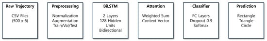
Figure 8.
Classification pipeline architecture: raw trajectory data (500 × 6), preprocessing (normalization, augmentation), BiLSTM encoder (2 layers, 128 units), attention mechanism, and fully connected classifier with softmax output.
2.4.3. Training Procedure
The model was trained using the Adam optimizer with an initial learning rate of 0.001 and cross-entropy loss function. Training was conducted for 50 epochs with a batch size of 16. Gradient clipping with a maximum norm of 1.0 was applied to prevent gradient explosion. Model performance was evaluated on the validation set after each epoch, and the model with the highest validation accuracy was saved. Final model evaluation was conducted on the held-out test set using the best-performing checkpoint. The model was implemented in PyTorch 2.8.0 with CUDA 12.8 and trained on a workstation equipped with an AMD Ryzen 9 9950X3D processor, NVIDIA GeForce RTX 5070 Ti GPU (NVIDIA, Santa Clara, CA, USA), and Windows 11 operating system.
3. Results
3.1. System Integration and Functionality
The assembled 6-DOF robotic arm successfully demonstrated basic operational capabilities required for teaching-based trajectory recording. All six joints responded to position commands via CAN communication, and the teaching mode enabled manual manipulation with appropriate brake current for data collection. The system maintained stable operation throughout the demonstration recording sessions.
3.2. Teaching Mode Data Collection
A total of 45 demonstration trajectories were successfully recorded (15 per pattern class) with trajectory durations ranging from 4.2 to 8.7 s after preprocessing. The preprocessing step removed initial descent phases by detecting when the end-effector z-coordinate descended below 0.20 m, with cleaned trajectories maintaining an average sampling rate of approximately 100 Hz.
Figure 9 shows representative end-effector trajectories for the three geometric patterns in top view. Visual inspection revealed characteristic signatures for each pattern: circle patterns displayed smooth curved paths with consistent radius, triangle patterns showed three sharp vertices with approximately straight edges, and rectangle patterns exhibited distinct right-angle corners.
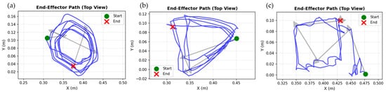
Figure 9.
Representative end-effector trajectories for the three geometric patterns collected via teaching mode (top view, XY plane). (a) Circle pattern displaying smooth curved trajectory. (b) Triangle pattern with three distinct vertices. (c) Rectangle pattern showing right-angle corners. Green and red markers denote start and end positions, respectively. The blue lines represent the end-effector trajectories recorded during the teaching process, and the gray arrows indicate the movement direction along the trajectories.
3.3. Model Training and Evaluation
The BiLSTM attention model was trained for 50 epochs with a batch size of 16 using the Adam optimizer (learning rate = 0.001). The model achieved a maximum validation accuracy of 85.19% at epoch 24, which was selected as the best checkpoint for final evaluation. Training accuracy reached 98.89% by epoch 50, while validation accuracy declined to 64.81%, indicating overfitting despite dropout regularization (p = 0.3) and data augmentation.
Figure 10 illustrates the training and validation curves over 50 epochs. The training loss decreased consistently from 1.10 to 0.06, while validation loss increased after epoch 24, reaching values above 2.5 in later epochs (Figure 10a). Similarly, training accuracy improved steadily to 98.89%, whereas validation accuracy peaked at 85.19% at epoch 24 and subsequently fluctuated between 63% and 78% (Figure 10b). This divergence between training and validation metrics clearly demonstrates overfitting, where the model memorized training patterns but failed to generalize to unseen data.
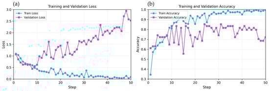
Figure 10.
Training and validation performance over 50 epochs. (a) Loss curves showing divergence after epoch 4, indicating overfitting. Training loss decreased consistently while validation loss increased substantially. (b) Accuracy curves demonstrating peak validation performance at epoch 24 (85.19%) followed by performance degradation despite continued improvement in training accuracy (98.89% at epoch 50).
The best BiLSTM+Attention model (epoch 24) achieved an overall test accuracy of 83.33% on the held-out test set (n = 36 samples, 12 per class). Table 3 presents the confusion matrix showing classification performance across the three geometric patterns.
Table 3.
Confusion matrix for pattern classification on the test set.
Per-class performance metrics revealed varying recognition capabilities across patterns (Table 4). Rectangle patterns achieved the highest recall (91.67%) with F1-score of 78.57%, with 11 out of 12 samples correctly classified. Triangle patterns demonstrated perfect precision (100.00%) but moderate recall (66.67%) due to confusion with rectangle patterns, as 4 out of 12 triangle samples were misclassified as rectangles. Circle patterns achieved the highest overall performance with balanced precision and recall (91.67%), demonstrating robust recognition of curved trajectories. The confusion between triangle and rectangle patterns likely stems from the similarity in linear segment features, as both patterns involve straight-line movements that may be difficult to distinguish with limited training data.
Table 4.
Per-class classification performance metrics.
The results demonstrate proof-of-concept feasibility for teaching-based pattern recognition in robotic food decoration applications. However, the significant overfitting and moderate test accuracy suggest that larger datasets or alternative network architectures may be required for robust real-world deployment. To validate the BiLSTM+Attention architecture, comprehensive comparison was conducted with four baseline models trained on identical data splits: Random Forest, 1D-CNN, GRU, and TCN. Table 5 presents the comparative results. BiLSTM+Attention achieved the highest test accuracy (83.33%) among deep learning approaches, while Random Forest performed best overall (86.11%), likely due to its effectiveness with limited training data.
Table 5.
Performance comparison of baseline models trained on identical data splits.
4. Discussion
4.1. Teaching-Based Data Collection
This study successfully demonstrated a teaching-based approach for collecting demonstration data from a custom-built 6-DOF robotic arm without requiring complex inverse kinematics modeling. The teaching mode implementation, which applied differential brake currents to joints based on their gear ratios, enabled intuitive manual manipulation while maintaining trajectory quality. The preprocessing pipeline effectively removed non-productive motion phases using a z-coordinate threshold, resulting in clean trajectory data suitable for machine learning. The tf2-based forward kinematics computation provided real-time end-effector pose estimation at 100 Hz, demonstrating the practical utility of URDF-based robot modeling for rapid prototyping applications.
The teaching-based approach demonstrated significant advantages over traditional inverse kinematics (IK) modeling for this food processing application. Conventional analytical IK solutions for 6-DOF manipulators require exact knowledge of link lengths, joint offsets, and Denavit–Hartenberg parameters, which are challenging to obtain accurately in custom-built systems using 3D-printed components with inherent dimensional variations [44]. Furthermore, analytical IK often produces multiple solutions or singularities that require careful handling [25]. The complex mathematical derivation process and high computational complexity of analytical methods limit their practical applicability in small-scale manufacturing environments where rapid deployment and reconfiguration are essential. Data-driven IK approaches using neural networks [26,27,28,29,30] can address these issues but require extensive training datasets collected through precision measurement equipment, which may not be feasible for small-scale manufacturing environments. In contrast, the teaching-based method circumvents these challenges by directly recording demonstrated trajectories that inherently incorporate all mechanical characteristics, including manufacturing tolerances, reducer backlash, and motor response dynamics—without requiring explicit mathematical modeling. The operator’s physical demonstration automatically generates training data that reflects the actual robot’s behavior, eliminating calibration overhead and enabling rapid deployment. This approach is particularly valuable for food processing applications where trajectory patterns are repetitive but spatially varied, and where the cost and complexity of traditional robotic programming may be prohibitive for small-scale producers.
4.2. Pattern Recognition Performance
The BiLSTM+attention model achieved 83.33% test accuracy, demonstrating proof-of-concept feasibility for trajectory-based pattern classification. The model successfully distinguished all three patterns, with circles achieving the highest F1-score (91.67%), rectangles at 78.57%, and triangles at 80.00%. However, confusion between triangles and rectangles was observed, as 4 out of 12 triangle samples were misclassified as rectangles due to similarity in linear segment features. The baseline comparison (Table 5) confirms BiLSTM+Attention achieved the highest accuracy among deep learning approaches, validating the architecture choice for this sequential trajectory classification task. The BiLSTM architecture demonstrated sufficient performance for proof-of-concept validation, though future work could compare alternative architectures such as 1D CNNs or temporal convolutional networks with larger datasets. This suggests that position-based features alone may be insufficient for discriminating curved patterns, particularly when manual demonstrations introduce variability in execution speed and smoothness.
The demonstrated pattern recognition capability has direct applicability to food decoration tasks where geometric patterns are frequently used, such as icing borders on cakes or chocolate drizzling patterns. The teaching-based approach allows food processing operators without robotics expertise to program new decoration patterns by simply demonstrating them manually. The severe overfitting observed after epoch 24, despite five-fold data augmentation and dropout regularization, indicates that the dataset size (270 samples) remained inadequate for training deep recurrent networks. The peak validation accuracy of 85.19% at epoch 24, followed by degradation to 65% by epoch 50, suggests that early stopping mechanisms are critical for small-dataset scenarios. Alternative approaches such as transfer learning from larger trajectory datasets or simpler model architectures like 1D convolutional networks or Random Forests may provide better generalization with limited training data.
4.3. System Repeatability and Practical Considerations
The teaching-based demonstration system was evaluated for consistency across multiple trajectory recordings. Due to the manual nature of the teaching mode, where the operator physically guides the end-effector along physical templates, demonstration-to-demonstration variability includes both template placement variation and natural human movement characteristics. The mechanical design, featuring high gear reduction ratios (64:1 for joints 1–2, 10:1 for joints 3–4, 6:1 for joints 5–6) and high-resolution encoders, ensures precise trajectory recording during manual demonstration. The system successfully recorded 45 demonstrations across three geometric patterns with consistent data quality at 100 Hz sampling rate. While quantitative within-operator repeatability analysis revealed variability inherent to manual demonstration methods, the pattern recognition model achieved 83.33% classification accuracy, demonstrating that the BiLSTM network successfully learned to identify geometric pattern characteristics despite demonstration variability. This proof-of-concept validation confirms the feasibility of teaching-based pattern recognition for food processing applications, though deployment in production environments would require additional refinement including constrained demonstration protocols and potentially automated trajectory correction mechanisms.
4.4. Limitations
This study successfully demonstrated the proof-of-concept feasibility of a teaching-based pattern recognition system using a low-cost, custom-built robotic arm. However, as the research scope was focused on the viability of the ML-based pattern classification rather than industrial-grade control, several limitations must be acknowledged.
First, the system lacks a rigorous mathematical model of its dynamics. The dynamic equations of motion, nonlinear friction models (e.g., static friction, backlash), and joint compliance were not incorporated. While the teaching-based approach inherently captures some of these effects in the demonstrated data, the absence of explicit modeling and compensation limits the system’s precision and repeatability, especially during trajectory replay at varying speeds or under load.
Second, the control framework is limited to trajectory replay without a feedback control law for dynamic compensation. Consequently, the system’s robustness against external disturbances or payload variations was not validated. The current 100 Hz control loop frequency in ROS 2 may also introduce latency, limiting performance in high-speed tasks.
Third, the machine learning model faces challenges related to data scarcity and feature representation. The dataset, while augmented to 270 samples, originates from only 45 demonstrations, leading to the observed overfitting. Furthermore, the model relies solely on end-effector position data, neglecting richer dynamic states (e.g., joint torques, acceleration) or sensor-fused data (e.g., IMU) that could improve classification robustness. The data augmentation was purely geometric and did not account for temporal noise or sensor drift.
Finally, the performance evaluation was limited. From a control perspective, standard trajectory tracking metrics (e.g., RMSE, IAE) were not presented. From an ML perspective, the evaluation was limited to classification metrics (Accuracy, F1-score) and did not include time-series specific metrics like Dynamic Time Warping (DTW) or comparisons to simpler baseline models.
5. Conclusions
This study successfully demonstrated a teaching-based robotic system for pattern recognition in food processing applications. A custom 6-DOF robotic arm was developed using modular brushless motors controlled via CAN communication and ROS 2, enabling intuitive trajectory recording through manual demonstration without requiring complex inverse kinematics programming.
The system achieved 83.33% test accuracy in classifying three geometric patterns, demonstrating the best performance among deep learning approaches and validating the BiLSTM+Attention architecture through comprehensive baseline comparison with Random Forest, 1D-CNN, TCN, and GRU models. Circle patterns achieved the highest F1-score (91.67%), followed by triangles (80.00%) and rectangles (78.57%). The key contributions include implementation of an accessible teaching mode that allows non-expert users to demonstrate trajectories through physical guidance, automatic computation of end-effector poses through forward kinematics at 100 Hz, and successful pattern classification from limited demonstration data using a BiLSTM attention network.
These results establish the feasibility of teaching-based approaches for robotic food decoration, providing an accessible pathway for small-scale food manufacturers and artisanal producers. The rapid training time and minimal computational requirements suggest practical deployment on modest hardware platforms. Future work will focus on addressing these limitations to enhance the system’s robustness and scalability for real-world deployment.
First, we will develop a comprehensive dynamic model of the manipulator. This includes performing system identification to quantify parameters such as mass, inertia, and nonlinear friction, and incorporating these into the control framework for friction compensation and improved trajectory tracking.
Second, we will integrate a robust feedback control layer, such as a PID controller combined with an adaptive disturbance observer or a model-based reinforcement learning agent. Recent advances in reinforcement learning for robotic control, including DDPG variants such as LC-DDPG and TD3-ADX [45], provide promising benchmarking methodologies for such comparative evaluations. This will enable the robot to reject external disturbances, compensate for payload variations, and improve overall trajectory accuracy. A comparative study benchmarking this hybrid controller against traditional PID and model-free RL baselines (e.g., DDPG, TD3) will be conducted. Performance will be quantified using standard control metrics (RMSE, settling time, IAE) under various disturbance scenarios.
Third, the pattern recognition framework will be improved by (1) significantly expanding the dataset with demonstrations from multiple users at various speeds, (2) integrating dynamic features (e.g., joint torques, velocities) and sensor-fused data (e.g., IMU) into the ML model, and (3) evaluating a wider range of models, including 1D-CNNs and simpler baselines, using time-series metrics like DTW.
Finally, we will validate the complete system in real-world food dispensing tasks, quantitatively analyzing the impact of hardware factors (e.g., CAN latency, mechanical stiffness, thermal stress) and environmental disturbances (e.g., material viscosity) on end-effector precision.
This research demonstrates that intuitive teaching-based programming combined with machine learning pattern recognition can democratize industrial automation in specialized food processing applications. The approach enables automation of repetitive decorating tasks while retaining creative control through direct demonstration.
Author Contributions
Conceptualization, Y.K. and S.K.; methodology, Y.K.; software, Y.K.; validation, Y.K.; data curation, Y.K.; writing—original draft preparation, Y.K.; writing—review and editing, Y.K. and S.K.; visualization, Y.K.; supervision, S.K.; funding acquisition, S.K. All authors have read and agreed to the published version of the manuscript.
Funding
This research was supported by Korea Institute of Marine Science & Technology Promotion (KIMST) funded by the Ministry of Oceans and Fisheries, Korea (RS-2024-00404779).
Institutional Review Board Statement
Not applicable.
Informed Consent Statement
Not applicable.
Data Availability Statement
The original contributions presented in the study are included in the article; further inquiries can be directed to the corresponding author.
Acknowledgments
During the preparation of this manuscript, the authors used Claude Sonnet 4.5 (Anthropic, September 2025) for the purpose of English translation. The authors have reviewed and edited the output and take full responsibility for the content of this publication.
Conflicts of Interest
The authors declare no conflicts of interest.
References
- Li, D.; Xu, X. Industry 4.0—Frontiers of Fourth Industrial Revolution. Syst. Res. Behav. Sci. 2020, 37, 531–534. [Google Scholar] [CrossRef]
- Raja Santhi, A.; Muthuswamy, P. Influence of Blockchain Technology in Manufacturing Supply Chain and Logistics. Logistics 2022, 6, 15. [Google Scholar] [CrossRef]
- Kok, C.L.; Heng, J.B.; Koh, Y.Y.; Teo, T.H. Energy-, Cost-, and Resource-Efficient IoT Hazard Detection System with Adaptive Monitoring. Sensors 2025, 25, 1761. [Google Scholar] [CrossRef] [PubMed]
- Qiu, F.; Kumar, A.; Hu, J.; Sharma, P.; Tang, Y.B.; Xu Xiang, Y.; Hong, J. A Review on Integrating IoT, IIoT, and Industry 4.0: A Pathway to Smart Manufacturing and Digital Transformation. IET Inf. Secur. 2025, 2025, 9275962. [Google Scholar] [CrossRef]
- Soori, M.; Arezoo, B.; Dastres, R. Internet of Things for Smart Factories in Industry 4.0, a Review. Internet Things Cyber-Phys. Syst. 2023, 3, 192–204. [Google Scholar] [CrossRef]
- Soori, M.; Dastres, R.; Arezoo, B.; Karimi Ghaleh Jough, F. Intelligent Robotic Systems in Industry 4.0: A Review. J. Adv. Manuf. Sci. Technol. 2024, 4, 2024007. [Google Scholar] [CrossRef]
- Bader, F.; Rahimifard, S. Challenges for Industrial Robot Applications in Food Manufacturing. In Proceedings of the 2nd International Symposium on Computer Science and Intelligent Control, Stockholm, Sweden, 21 September 2018; pp. 1–8. [Google Scholar]
- Wakchaure, Y.B.; Patle, B.K.; Pawar, S. Prospects of Robotics in Food Processing: An Overview. J. Mech. Eng. Autom. Control. Syst. 2023, 4, 17–37. [Google Scholar] [CrossRef]
- Woo, S.; Kim, Y.; Kim, S. Converging Extended Reality and Robotics for Innovation in the Food Industry. AgriEngineering 2025, 7, 322. [Google Scholar] [CrossRef]
- Raja Santhi, A.; Muthuswamy, P. Industry 5.0 or Industry 4.0S? Introduction to Industry 4.0 and a Peek into the Prospective Industry 5.0 Technologies. Int. J. Interact. Des. Manuf. 2023, 17, 947–979. [Google Scholar] [CrossRef]
- Iqbal, J.; Islam, R.U.; Abbas, S.Z.; Khan, A.A.; Ajwad, S.A. Automating Industrial Tasks Through Mechatronic Systems—A Review of Robotics in Industrial Perspective. Teh. Vjesn. 2016, 23, 881–887. [Google Scholar]
- Hossain, D.; Capi, G.; Jindai, M.; Kaneko, S. Pick-Place of Dynamic Objects by Robot Manipulator Based on Deep Learning and Easy User Interface Teaching Systems. Ind. Robot 2017, 44, 11–20. [Google Scholar] [CrossRef]
- Phuyal, S.; Bista, D.; Bista, R. Challenges, Opportunities and Future Directions of Smart Manufacturing: A State of Art Review. Sustain. Futures 2020, 2, 100023. [Google Scholar] [CrossRef]
- Su, B. Tracking Control of Robotic Manipulator End-Effector Trajectory Based on Robust Sliding Mode Method. PLoS ONE 2025, 20, e0320118. [Google Scholar] [CrossRef] [PubMed]
- Zhao, C.; Wei, Y.; Xiao, J.; Sun, Y.; Zhang, D.; Guo, Q.; Yang, J. Inverse Kinematics Solution and Control Method of 6-Degree-of-Freedom Manipulator Based on Deep Reinforcement Learning. Sci. Rep. 2024, 14, 12467. [Google Scholar] [CrossRef]
- Gao, R. Inverse Kinematics Solution of Robotics Based on Neural Network Algorithms. J. Ambient Intell. Humaniz. Comput. 2020, 11, 6199–6209. [Google Scholar] [CrossRef]
- Stifter, S. Algebraic Methods for Computing Inverse Kinematics. J. Intell. Robot. Syst. 1994, 11, 79–89. [Google Scholar] [CrossRef]
- Lee, C.S.G.; Ziegler, M. Geometric Approach in Solving Inverse Kinematics of PUMA Robots. IEEE Trans. Aerosp. Electron. Syst. 1984, 20, 695–706. [Google Scholar] [CrossRef]
- Angeles, J. On the Numerical Solution of the Inverse Kinematic Problem. Int. J. Robot. Res. 1985, 4, 21–37. [Google Scholar] [CrossRef]
- Kucuk, S.; Bingul, Z. The Inverse Kinematics Solutions of Industrial Robot Manipulators. In Proceedings of the 2004 IEEE International Conference on Mechatronics, ICM’04, Istanbul, Turkey, 3–5 June 2004; pp. 274–279. [Google Scholar]
- Peiper, D.L. The Kinematics of Manipulators Under Computer Control; Technical Report CS-116; Department of Computer Science, Stanford University: Stanford, CA, USA, 1968. [Google Scholar]
- Primrose, E.J.F. On the Input-Output Equation of the General 7R-Mechanism. Mech. Mach. Theory 1986, 21, 509–510. [Google Scholar] [CrossRef]
- Liao, Q.; Liang, C.; Zhang, Q. A Novel Approach to the Displacement Analysis of General Spatial 7R Mechanism. Chin. J. Mech. Eng. 2009, 22, 336–344. [Google Scholar]
- Lee, H.Y.; Liang, C.G. Displacement Analysis of the General Spatial 7-Link 7R Mechanism. Mech. Mach. Theory 1988, 23, 219–226. [Google Scholar] [CrossRef]
- Raghavan, M.; Roth, B. Inverse Kinematics of the General 6R Manipulator and Related Linkages. J. Mech. Des. 1993, 115, 502–508. [Google Scholar] [CrossRef]
- Köker, R.; Öz, C.; Çakar, T.; Ekiz, H. A Study of Neural Network Based Inverse Kinematics Solution for a Three-Joint Robot. Robot. Auton. Syst. 2004, 49, 227–234. [Google Scholar] [CrossRef]
- Köker, R. A Genetic Algorithm Approach to a Neural-Network-Based Inverse Kinematics Solution of Robotic Manipulators Based on Error Minimization. Inf. Sci. 2013, 222, 528–543. [Google Scholar] [CrossRef]
- Csiszar, A.; Eilers, J.; Verl, A. On Solving the Inverse Kinematics Problem Using Neural Networks. In Proceedings of the 2017 24th International Conference on Mechatronics and Machine Vision in Practice (M2VIP), Auckland, New Zealand, 21–23 November 2017; pp. 1–6. [Google Scholar]
- Hasan, A.T.; Hamouda, A.M.S.; Ismail, N.; Al-Assadi, H.M.A.A. An Adaptive-Learning Algorithm to Solve the Inverse Kinematics Problem of a 6 DOF Serial Robot Manipulator. Adv. Eng. Softw. 2006, 37, 432–438. [Google Scholar] [CrossRef]
- Lu, J.; Zou, T.; Jiang, X. A Neural Network Based Approach to Inverse Kinematics Problem for General Six-Axis Robots. Sensors 2022, 22, 8909. [Google Scholar] [CrossRef]
- Argall, B.D.; Chernova, S.; Veloso, M.; Browning, B. A Survey of Robot Learning from Demonstration. Robot. Auton. Syst. 2009, 57, 469–483. [Google Scholar] [CrossRef]
- Ravichandar, H.; Polydoros, A.S.; Chernova, S.; Billard, A. Recent Advances in Robot Learning from Demonstration. Annu. Rev. Control Robot. Auton. Syst. 2020, 3, 297–330. [Google Scholar] [CrossRef]
- Kormushev, P.; Calinon, S.; Caldwell, D.G. Imitation Learning of Positional and Force Skills Demonstrated via Kinesthetic Teaching and Haptic Input. Adv. Robot. 2011, 25, 581–603. [Google Scholar] [CrossRef]
- Ye, Y.; Nie, Z.; Liu, X.; Xie, F.; Li, Z.; Li, P. ROS2 Real-Time Performance Optimization and Evaluation. Chin. J. Mech. Eng. 2023, 36, 144. [Google Scholar] [CrossRef]
- Macenski, S.; Foote, T.; Gerkey, B.; Lalancette, C.; Woodall, W. Robot Operating System 2: Design, Architecture, and Uses in the Wild. Sci. Robot. 2022, 7, eabm6074. [Google Scholar] [CrossRef]
- Kim, Y.; Kim, S. Automation and Optimization of Food Process Using CNN and Six-Axis Robotic Arm. Foods 2024, 13, 3826. [Google Scholar] [CrossRef]
- Iwana, B.K.; Uchida, S. An Empirical Survey of Data Augmentation for Time Series Classification with Neural Networks. PLoS ONE 2021, 16, e0254841. [Google Scholar] [CrossRef] [PubMed]
- Wen, Q.; Sun, L.; Yang, F.; Song, X.; Gao, J.; Wang, X.; Xu, H. Time Series Data Augmentation for Deep Learning: A Survey. In Proceedings of the Thirtieth International Joint Conference on Artificial Intelligence, Montreal, QC, Canada, 19–27 August 2021; pp. 4653–4660. [Google Scholar]
- Iglesias, G.; Talavera, E.; González-Prieto, Á.; Mozo, A.; Gómez-Canaval, S. Data Augmentation Techniques in Time Series Domain: A Survey and Taxonomy. Neural Comput. Applic. 2023, 35, 10123–10145. [Google Scholar] [CrossRef]
- Siami-Namini, S.; Tavakoli, N.; Namin, A.S. The Performance of LSTM and BiLSTM in Forecasting Time Series. In Proceedings of the 2019 IEEE International Conference on Big Data (Big Data), Los Angeles, CA, USA, 9–12 February 2019; pp. 3285–3292. [Google Scholar]
- Fan, Y.; Tang, Q.; Guo, Y.; Wei, Y. BiLSTM-MLAM: A Multi-Scale Time Series Prediction Model for Sensor Data Based on Bi-LSTM and Local Attention Mechanisms. Sensors 2024, 24, 3962. [Google Scholar] [CrossRef]
- Xu, Y.; Pan, Q.; Wang, Z.; Hu, B. A Novel Trajectory Prediction Method Based on CNN, BiLSTM, and Multi-Head Attention Mechanism. Aerospace 2024, 11, 822. [Google Scholar] [CrossRef]
- Hochreiter, S.; Schmidhuber, J. Long Short-Term Memory. Neural Comput. 1997, 9, 1735–1780. [Google Scholar] [CrossRef]
- Khanesar, M.A.; Yan, M.; Isa, M.; Piano, S.; Branson, D.T. Precision Denavit–Hartenberg Parameter Calibration for Industrial Robots Using a Laser Tracker System and Intelligent Optimization Approaches. Sensors 2023, 23, 5368. [Google Scholar] [CrossRef]
- Hazem, Z.B.; Saidi, F.; Guler, N.; Altaif, A.H. Reinforcement Learning-Based Intelligent Trajectory Tracking for a 5-DOF Mitsubishi Robotic Arm: Comparative Evaluation of DDPG, LC-DDPG, and TD3-ADX. Int. J. Intell. Robot Appl. 2025. [Google Scholar] [CrossRef]


Disclaimer/Publisher’s Note: The statements, opinions and data contained in all publications are solely those of the individual author(s) and contributor(s) and not of MDPI and/or the editor(s). MDPI and/or the editor(s) disclaim responsibility for any injury to people or property resulting from any ideas, methods, instructions or products referred to in the content. |
© 2025 by the authors. Licensee MDPI, Basel, Switzerland. This article is an open access article distributed under the terms and conditions of the Creative Commons Attribution (CC BY) license (https://creativecommons.org/licenses/by/4.0/).