Abstract
This study presents an in-depth investigation of an eccentric double-ring microwave resonator comprising two asymmetrically coupled conductive loops connected at a single point. The configuration was systematically analyzed using analytical modeling, full-wave electromagnetic simulations (Ansys HFSS), and experimental characterization. Analytical formulations based on the resonant condition of thin conductive rings provided theoretical estimates of the fundamental and higher-order eigenmodes, while simulations yielded accurate resonance frequencies, transmission responses, and electric field distributions. The transmission coefficient (S21) exhibited two distinct resonance dips at 436 MHz and 708 MHz, confirming strong inter-ring coupling and hybrid mode formation. Electric field mapping revealed pronounced confinement within the resonator region (E > 170 V/m) and substantial attenuation of the transmitted field (E < 13 V/m), demonstrating efficient electromagnetic energy suppression. Experimental results showed excellent consistency with theoretical predictions. This paper aims to establish a compact, low-cost, and tunable resonant structure capable of frequency-selective attenuation and field confinement without using lossy materials. Unlike conventional symmetric resonators, the eccentric configuration enables enhanced coupling control and modal diversity, making it highly relevant for the design of next-generation electromagnetic shielding, filtering, and sensing systems.
1. Introduction
Ring-shaped microwave resonators are fundamental components in the design of resonant networks intended for electromagnetic (EM) wave suppression within specified frequency bands. Accurate identification of their resonant frequencies is essential for predicting and optimizing the overall network performance. This study investigates a resonator topology comprising conductive rings arranged eccentrically so that they make contact at a single point.
Research on microwave ring resonators has expanded rapidly over the past decade, particularly regarding multi-ring, concentric, and eccentric configurations applied in filtering, sensing, and electromagnetic shielding.
Many years ago, resonators based on split rings were studied, and research demonstrated their positive characteristics and various useful applications. For example, in [1] (2004), Kastrakis et al. described the electric excitation of magnetic resonance (EEMR) effect, which is distinct from the SRR’s response to a magnetic field that is excited when the incident magnetic field is perpendicular to the gap. In closely spaced SRR arrays, the electric and magnetic couplings between the resonators can also be strong and influence each other, leading to complex behavior such as modified resonance frequencies and transmission dips. In 2005, Baena et al. presented a new approach to developing planar metamaterial structures based on split-ring resonators, which find application in devices operating in the microwave region [2]. Landy and his associates also worked with metamaterial-based absorbers in 2008 [3]. Shadrivov et al. experimentally studied split-ring resonators and showed that the eigenfrequencies of the resonators can be tuned over a wide frequency range [4]. In addition, in 2008, Aydin and his colleagues studied split ring resonators (SRR) to improve electromagnetic wave transmission through subwavelength apertures [5]. In his paper published in 2010, Cheng presented a polarization-insensitive metamaterial absorber comprising a dielectric substrate with a split-ring-cross resonator and a continuous metal film. The experiment demonstrated excellent field absorption at high frequencies [6]. Kapoor et al. [7] demonstrated that coupled ring resonators enable precise dielectric material characterization due to strong EM interaction, while Islam et al. [8] presented a mutually coupled concentric crossed-line split-ring resonator, demonstrating strong mode coupling and tunable responses in the C, X, and Ku bands. Furthermore, ring resonators are widely recognized for their compact structure, high Q-factor, and ease of integration into planar microwave systems [8,9]. Alahnomi et al. [9] provided a detailed review of planar resonator-based sensors, highlighting advances in high sensitivity and multi-band applications. Hossain et al. [10] reported multilayer metamaterial absorbers using E-shaped and ring-based resonators that achieved high absorption over targeted frequency ranges. Recent studies have explored the effect of eccentric coupling between rings, which modifies field confinement and broadens the resonance bandwidth [11,12]. Walsten et al. [12] experimentally compared single and concentric split-ring resonators and confirmed significant improvements in field localization. In addition to sensing and filtering, ring resonators have been investigated for electromagnetic shielding and absorption [10,13,14]. Liu et al. [13] showed that embedding split-ring resonators into composite fabrics substantially enhances electromagnetic shielding effectiveness. Such innovations underline the versatility of ring-resonator topologies for compact and tunable EM structures [15,16,17]. Other recent developments include metamaterial absorbers with flexible substrates [18], biodegradable resonator sensors [19], and quad-band resonator arrays for advanced wireless systems [20]. Rabani et al. designed a metamaterial absorber for S, X, and Ku-band frequencies, achieving peak absorption in each band at 3.26 GHz, 11.6 GHz, and 17.13 GHz, respectively. The design uses a modified circular ring resonator structure with a dumbbell-shaped element and is intended for use in microwave sensing applications. Metamaterials like this are engineered materials that manipulate waves through their structure rather than their composition and can be used in applications like sensing, wireless communication, and radars [21]. In [22], Jahan et al. researched a metamaterial absorber (PMA) for multiple sensing applications. The PMA consists of two split ring resonators with six split gaps, configured to exhibit rotational symmetry.
As shown above, most available literature and scientific research focus on metamaterial structures comprising up to a hundred elementary units—rings arranged in a network —which operate at extremely high frequencies (up to 40 GHz). The aim of this research was to analyze how an eccentric ring composed of only two basic elements (rings) can attenuate electric field strength in the lower high-frequency range (below 1 GHz). These frequencies are widely used (e.g., military VHF/UHF, biomedical telemetry, FM, GSM, DVB-T2, IoT, 5G NR), and it is necessary to determine how field suppression can be achieved specifically in this frequency range. By using only one physical element (with an eccentric connection of the rings), the field on the ring can be clearly localized, while the field behind the ring can be significantly attenuated. As this research involves a metal wire and a copper ring, emphasis is also placed on the simplicity of construction and the low fabrication cost of the structure, making it particularly suitable for EM shielding below 1 GHz.
In this paper, we propose and experimentally verify a microwave resonator consisting of two eccentrically coupled conductive rings connected at a single point. Analytical modeling, full-wave simulation (Ansys HFSS), and experimental validation were used to determine resonant frequencies, field distributions, and transmission characteristics. The proposed structure is analyzed as a potential unit element for resonant networks designed to suppress electromagnetic wave propagation in selected frequency ranges.
2. Design Requirements and Modeling
The aim of this research was to develop a resonator structure capable of reducing the electromagnetic field level within a targeted frequency range, suitable for use as an absorber network to protect human environments or to ensure the proper operation of nearby devices.
Two key questions arise:
- (1)
- What is the target frequency range?
- (2)
- What should the resonator configuration be?
The frequency range of interest can be determined based on the known state of the electromagnetic spectrum and previous measurements of ambient EM levels. Figure 1 shows the most significant field contributions in the target frequency range, particularly below 1 GHz, where stationary field sources such as FM radio, DVB-T2, 5G NR, and GSM are ubiquitous.
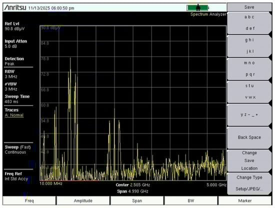
Figure 1.
Measured electric field contributions from stationary sources in the Republic of Croatia at frequencies below 1 GHz.
Among the available configurations, the circular ring resonator is compact, mechanically robust, and suitable for microwave applications. To broaden its operating frequency range, a modified dual-ring version was designed (Figure 2). Microwave ring resonators are widely used in telecommunications, optics, and integrated photonics as filters, oscillators, sensors, and multiplexers. Their inherent frequency selectivity enables their use as absorber components across broad frequency bands.
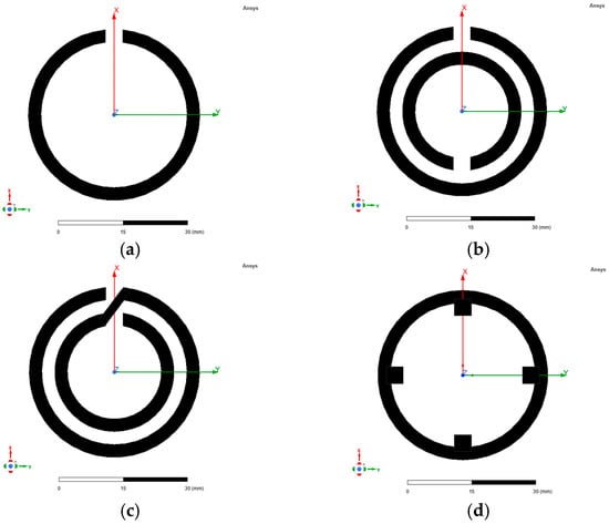
Figure 2.
Examples of microwave ring resonators: (a) split-ring resonator—one ring (SRR-1R); (b) split-ring resonator—two rings (SRR-2R); (c) spiral resonator (SR); (d) stub-loaded circular resonator.
3. Analytical and Numerical Modeling
3.1. Analytical Modeling
Analytical calculations were performed to estimate the resonant frequencies of the proposed structure, while full-wave electromagnetic simulations using Ansys HFSS verified these predictions. Resonance occurs when the ring circumference equals an integer multiple of the guided wavelength:
and the corresponding resonant frequency is:
where R is the ring radius, c the speed of light in air, and εeff the effective dielectric constant (εeff ≈ 1 for free space). This relation is valid for a thin conducting ring of radius R.
In accordance with the above, Figure 3 shows the actual behavior of the structure. It is struck by an electromagnetic wave of various frequencies (and wavelengths). The condition for resonance in this structure is that its physical length is a multiple of one of the wavelengths. It is important to determine this value in our case, because at this frequency the energy does not propagate further but is absorbed. In theory, multiple frequencies are involved, possibly even a range of frequencies. Based on the condition stated in (1), the resonance of each ring is calculated. After this, the resonant frequency can be determined according to (2).
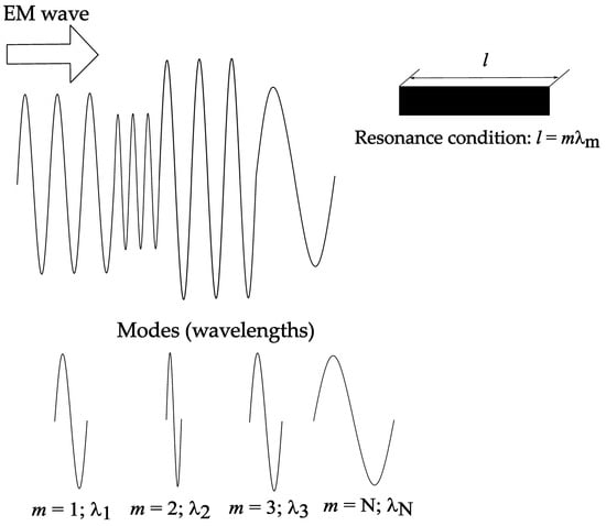
Figure 3.
Resonance when an EM wave reaches a device of length l.
If the ring has length, width, and height (see Figure 4), the effective radius is calculated according to Equation (3), where r is the radius, t the depth of the ring, and w ring width.
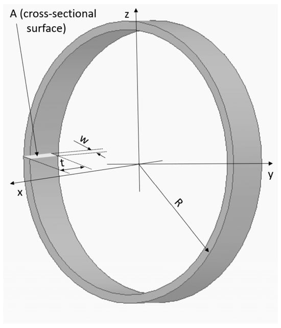
Figure 4.
Axonometric view of a cylindrical conducting ring.
The effective radius accounts for the width w and is therefore suitable for our intended purpose.
This paper analyzes a resonator constructed as a thin conductive ring (comprising two eccentric rings) as a basic resonator structure, and a conductive cylindrical ring as a resonator with high strength that can be used for applications such as forming an absorber network within a building material (e.g., concrete).
Table 1 and Table 2 present analytically determined resonant frequencies of thin and cylindrical conductive (a ring that can be applied in reality) rings. The selected radii (R1 = 95.0 mm, R2 = 66.5 mm) ensure that the first mode is below 1 GHz, with several higher modes below 2 GHz.

Table 1.
Analytical determination of resonant frequencies (MHz) for the first five modes of ring resonators with outer radius R and effective radius Reff using Equation (3)—large (outer) resonator ring.
Table 2.
Analytical determination of resonant frequencies (MHz) for the first five modes of ring resonators with outer radius R and effective radius Reff using Equation (3)—small (inner) resonator ring.
Table 1 and Table 2 detail the resonant frequency calculations for the individual rings, providing the values needed to create a real-world situation in HFSS.
The radii of the rings (outer and inner rings of the resonator) are selected so that the resonant frequency (first mode) is below 1 GHz. By setting the first mode resonant frequency below 1 GHz, the three modes of the outer (large—Figure 5b) ring and the two modes of the inner (small—Figure 5a) ring of the resonator fall within the target frequency range below 2 GHz. By connecting these two rings to form an eccentric resonator (Figure 5c), the attenuation regions (transmission reduction) are further extended around these resonances.
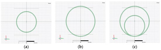
Figure 5.
Microwave ring resonator: (a) small resonator ring (R2 radius of the ring); (b) large resonator ring (R1 radius of the ring); (c) eccentric double-ring microwave resonator.
Table 3.
Analytical determination of resonant frequencies for the first five modes of eccentric ring resonators with different coupling factors k. Resonator dimensions: R1 = 95.0 mm; R2 = 66.5 mm (Coeff = 0.7); = 4 mm; t = 10 mm.
It can be concluded that an increase in the number of rings in such a resonator also increases the range of the resonant region within which the EM wave passing through it is attenuated.
A thicker ring has a shorter effective length, as the calculation uses the effective radius of the ring, which is smaller than the actual radius. Therefore, the resonant frequencies are slightly higher than for a thin ring. In practice, these values will be further shifted due to finite conductivity, distribution effects, and possible parasitic capacitances to the environment.
The resonator was shaped with two eccentrically connected rings to increase attenuation in the region below 2 GHz, which is critical in terms of transmission coefficients (very high transmission coefficients of the EM wave compared to the rest of the microwave spectrum (f > 2 GHz)), and includes many fixed sources of EM radiation (FM radio, DVBT2, 5G mobile telephony below 1 GHz, LTE 1600, etc.). To achieve this, the following ring radius values were chosen: R1 = 95 mm, R2 = 66.5 mm, = 4 mm, t = 10 mm.
If the resonator is represented by an equivalent circuit of two coupled inductances (with magnetic coupling factor k) without capacitive coupling (assumption), then a pair of separated resonance frequencies for such a structure can be determined. This pair of separated frequencies is based on the resonant angular frequencies of the individual rings (inductances) and , where and are the resonant frequencies of the individual rings (inductances), and is calculated according to the following relation:
where m—mode number, = m —resonant angular frequency of the mth mode of the first inductance (first resonant ring), = m —resonant angular frequency of the mth mode of the second inductance (second resonant ring), —resonant angular frequency of the first mode of the first isolated inductance (independent resonant ring, m = 1), and —resonant angular frequency of the first mode of the second isolated inductance (independent resonant ring, m = 1). See Table 1 and Table 2 (second column).
For the first mode, Relation (5) reads:
where m = 1, —resonant angular frequency of the first mode of the first inductance (resonant ring), and —resonant angular frequency of the second mode of the second inductance (resonant ring).
In accordance with the target frequency range, the radii of the resonant rings of the resonator were selected as follows: R1 = 95.0 mm and R2 = 66.5 mm. Using Relation (3), the resonant frequencies of the first mode of each ring are calculated, given the radius of each ring: = 502.30 MHz and = 717.50 MHz (see Table 1 and Table 2, column two), and then the split frequencies + and −. Table 3 presents the results of the split frequencies for the first five modes with different values of the coupling parameter k in the range from 0.0 to 0.75. The table shows the results separately for thin rings and for rings with cross-sectional dimensions = 3 mm and t = 10 mm, using the effective radii of these rings.
The following text refers to the parameter Coeff, which represents the ratio of the radii of the small and large rings (R2/R1), and is used in the simulation of the transmission parameter S21.
Since the effective radii are smaller than the actual radii in thin-wire rings, the resonant frequencies of these resonators are higher than those of thin-wire resonators. These changes are evident in the simulation results examining the influence of the resonator ring width w and ring thickness t on the transmission parameter, which are presented in the next chapter.
If, in addition to inductive coupling, capacitive coupling is also included in the analytical calculation, the resonator can be modeled as two series RLC circuits with mutual inductive (coefficient k) and capacitive coupling (C12). The analytical calculation then changes significantly, and the resonant frequencies are (according to [23]) calculated using the equation:
where
If the inductance values used in the previous model of the resonator with two inductances (L1 = 0.390 μH and L2 = 0.241 μH) are applied, along with the previously determined resonance frequencies of the ring resonator (Table 3—values k = 0, m = 1; −/ + = 513.05/739.74 MHz) from the resonance conditions (), the equivalent capacitances of each ring can be determined (C1 = 0.247 pF and C2 = 0.192 pF). Using Relation (6), and varying the values of the magnetic and capacitive coupling parameters, the results shown in Table 4, Table 5 and Table 6 are obtained. The selection of parameters for both types of coupling is based on the assumption of fairly strong inductive coupling (k > 0.3 represents strong coupling) and moderate to strong capacitive coupling (about 20% of the sum of both equivalent capacitances).
Table 4.
Analytical determination of resonant frequencies for the first five modes of eccentric ring resonators with a constant factor k = 0.435 and variable capacitive coupling (C12). Resonator dimensions: R1 = 95.0 mm; R2 = 66.5 mm (Coeff = 0.7); = 4 mm; t = 10 mm.
Table 5.
Analytical determination of resonant frequencies for the first five modes of eccentric ring resonators with a constant factor k = 0.445 and variable capacitive coupling (C12). Resonator dimensions: R1 = 95.0 mm; R2 = 66.5 mm (Coeff = 0.7); = 4 mm; t = 10 mm.
Table 6.
Analytical determination of resonant frequencies for the first five modes of eccentric ring resonators with constant factor k = 0.455 and variable capacitive coupling (C12). Resonator dimensions: R1 = 95.0 mm; R2 = 66.5 mm (Coeff = 0.7); = 4 mm; t = 10 mm.
For rough estimates of the resonant frequencies of the analyzed resonators, the first model used provides a very good approximation, while the analytical model accounting for both types of coupling, as expected, describes the operation of the ring eccentric resonators analyzed in this paper much more precisely.
3.2. Numerical Calculations—Simulations
Numerical simulations were conducted using the Ansys HFSS 2022/R1 software package. The simulations involved determining the eigenfrequencies of the resonator and the transmission coefficient as the electromagnetic wave passed through the resonator. The simulation models are shown in Figure 6.
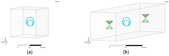
Figure 6.
HFSS simulation models for the analysis of microwave ring resonators: (a) eigenmode model; (b) S-parameter simulation setup with biconical antennas.
In this paper, two simulation models were used:
The first simulation model featured a resonator with variable outer and inner ring radii, as well as other geometric parameters, depending on the resonator configuration being calculated (a single or double ring resonator, and thin or cylindrical rings). This resonator was placed in a radiation space (air) with dimensions of 300 × 300 × 300 mm.
The second simulation model included two biconical antennas, each with a total length of l = 280 mm, a cone diameter of 100 mm, and a cone thickness of 2 mm, separated by 1690 mm. The analyzed resonator was positioned midway between them. Using this model, simulation calculations of the transmission coefficients and E field distribution were performed for all versions of the resonator with one and two rings (MODEL I and MODEL II). This assembly was placed in a radiation space (air) with dimensions of 800 × 800 × 3500 mm.
4. Simulation Results and Field Distribution
HFSS simulations determined the eigenfrequencies, S-parameters, and E-field distributions. Figure 7 and Figure 8 show how resonant frequencies vary with geometry. A second resonance at approximately 708 MHz appears due to inner-ring coupling, confirming bandwidth expansion.
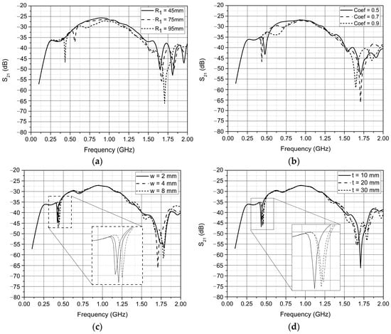
Figure 7.
Results of simulation calculation of coupling parameters S21: (a) with variation in the outer radius of the large resonator ring; (b) with variation in the coefficient of proportionality between the outer radii of the large and small resonator rings (Coeff = R2/R1); (c) with variation in the outer width w of the resonator ring; (d) with variation in the thickness t of the resonator ring.
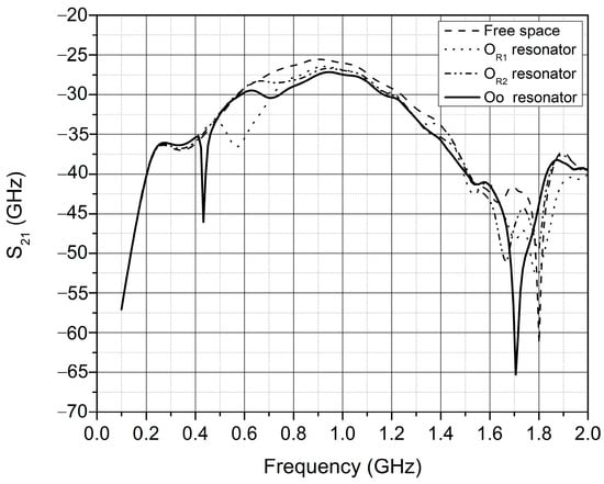
Figure 8.
Results of simulation calculation of ring resonators coupling parameters S21.
4.1. Coupling (Transmission) Parameters
Since the resonator under consideration represents the elementary unit of a resonant network, understanding its transmission characteristics is critically important for designing larger periodic structures.
Figure 7 and Figure 8 show that the resonant frequency of the ring resonator changes significantly with variations in the radius of the large ring, as expected. The resonant frequency increases as the radius of the large ring decreases (with other geometric parameters held constant: Coeff = 0.7, = 4 mm, t = 10 mm), rising from 435.70 MHz with R1 = 95.0 mm to 558.95 MHz with R1 = 75.0 mm, and reaching 1.01 GHz with R1 = 45.0 mm. Similarly, changing the proportionality ratio between the radii of the large and small rings also alters the resonant frequency. Adjusting this coefficient changes only the radius of the small ring, while the outer radius of the large ring remains constant at R1 = 95.0 mm.
Changing the thickness t and width w of the ring has a very small effect on the resonant frequency. It is important to note, as shown in Figure 7, that with the coefficient proportional to the large and small resonator rings, as well as with the resonator with R1 = 95 mm, a second resonance (a minimum of the S21-f curve) appears at 707.60 MHz. This is precisely the effect of expanding the frequency range of attenuation of the amplitude of the EM wave passing through the ring resonator constructed with an additional (inner) ring placed eccentrically.
This effect of widening the frequency range of amplitude attenuation of the EM wave passing through the ring resonator is particularly noticeable in Figure 8, which shows the transmission parameters of the eccentric ring resonator (marked as Oo resonator) with dimensions (R1 = 95.0 mm); Coeff = 0.7 (R2 = 66.5 mm; = 4 mm; t = 10 mm) and its rings as separate resonators (marked as OR1 and OR2). Resonators made with only one ring (OR1 and OR2) have only one resonance in this frequency range, namely f1 = 566.16 MHz (OR1) and f2 = 727.89 MHz (OR2), while in the case of resonators with both rings placed eccentrically (Figure 5), two resonances appear at 435.70 MHz and 707.60 MHz.
Determination of the change in resonant frequencies depending on the geometric parameters in this chapter was conducted with the aim of designing a ring eccentric microwave resonator. The effect of this resonator on the reduction in the transmission parameter at and outside the resonant frequencies was confirmed by calculating the distribution of the electric field strength in the next chapter.
4.2. Field Distribution Analysis
Following the transmission analysis, spatial field distributions were evaluated to understand energy localization within the resonator. At 436 MHz (resonance), the E-field shows strong confinement around the ring edges with E > 170 V/m, while behind the resonator (ANT2 plane) it drops to <13 V/m, confirming high attenuation. At 1.0 GHz (non-resonant), the field is uniform and weak (E < 60 V/m).
At the resonant frequency, strong confinement of the electric field (E-field) is observed in the immediate vicinity of the resonator (Figure 9a). Figure 9 shows the distribution of the electric field strength in the plane where the resonator is located and in the plane that horizontally intersects the antenna. The field vectors form closed, intensified loops around the edges of both rings, indicating constructive interference and the formation of a standing-wave pattern.
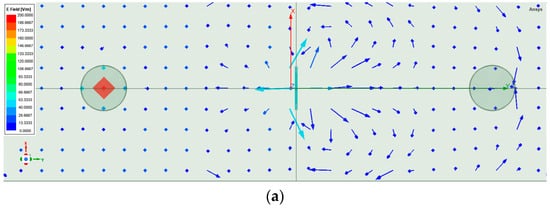
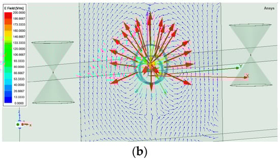
Figure 9.
Representation of the vector E field: (a) axonometric view of the vector E field in the resonator plane; (b) view of the vector E-field in the horizontal plane ANT1-REZONATOR-ANT2.
Maximum field magnitudes exceed 170 V/m, concentrated at the eccentric contact point between the inner and outer rings, where capacitive coupling dominates. This confirms the existence of a strong local resonance that enhances energy storage within the structure.
In contrast, at the non-resonant frequency of 1.0 GHz, the E-field is uniformly distributed, and its amplitude decreases sharply, remaining mostly below 60 V/m (see Figure 10). This reduction indicates that the structure acts as a low-loss scatterer outside the resonant region, allowing most of the incident energy to propagate through with minimal distortion.
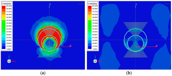
Figure 10.
Electric field strength distribution in the resonator plane: (a) First resonant frequency = 0.436 GHz (EMAX-RES = 186.7 to 200 V/m (red)); (b) Non-resonant frequency = 1.000 GHz (EMAX-RES = 26.7 to 53.3 V/m (light blue)).
The longitudinal field distribution between the antennas (Figure 9b) further demonstrates the attenuation effect at resonance. Along the propagation axis (ANT 1 → Resonator → ANT 2), the simulated E-field magnitude at the receiving antenna drops from 26.7 to 80 V/m (non-resonant) to 0–13.3 V/m (resonant), indicating a substantial decrease in transmitted field intensity (see Figure 11a,b). The corresponding S21 parameter minimum at 436 MHz matches this attenuation, confirming that the resonator efficiently absorbs or redirects a large portion of the incident electromagnetic energy. The same field behavior at the receiving antenna ANT2 applies at the frequency of 1 GHz (see Figure 11c,d).
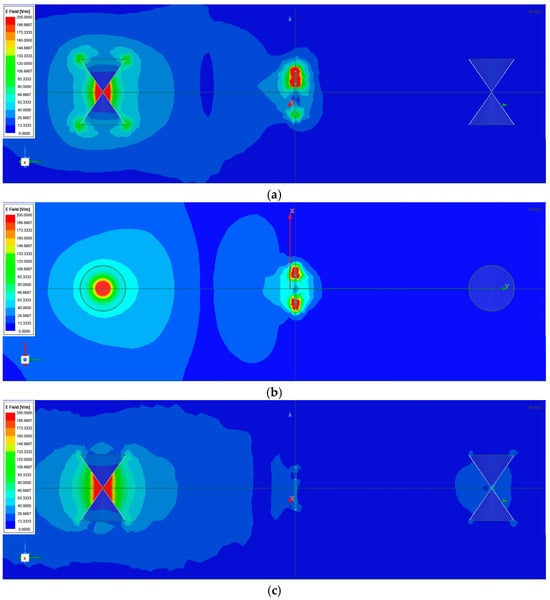
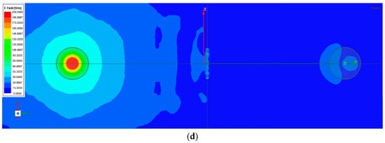
Figure 11.
Electric field strength distribution along the longitudinal plane (ANT1–ANT2): (a) Resonant frequency = 0.436 GHz, vertical plane (EMAX-RES = 186.7 to 200 V/m (red); EMAX-ANT2 ≤ 13.3 V/m (blue)); (b) Resonant frequency = 0.436 GHz, horizontal plane (EMAX-RES = 186.7 to 200 V/m (red); EMAX-ANT2 ≤ 13.3 V/m (blue)); (c) Non-resonant frequency = 1.000 GHz, vertical plane (EMAX-RES = 106.7 to 120.0 V/m (red); EMAX-ANT2 > 26.7 V/m (blue)); (d) Non-resonant frequency = 1.000 GHz, horizontal plane (EMAX-RES = 106.7 to 120.0 V/m (red); EMAX-ANT2 > 26.7 V/m (blue)).
Such a field pattern is typical of resonant metallic inclusions exhibiting both inductive and capacitive coupling. The enhanced field at the ring interface represents localized surface current accumulation and energy confinement, while the shadowed region behind the resonator indicates destructive interference between transmitted and reflected waves.
Overall, the simulation results clearly show that the eccentrically coupled double-ring resonator produces two distinct field-enhanced zones—one near each ring—and a pronounced shadowing region along the propagation path. This confirms its suitability for use as a unit absorber element or EM-shielding cell in larger resonant networks. The strong spatial localization of the E-field also suggests possible applications in near-field sensing and energy-harvesting structures where field confinement is desirable.
This pattern, typical of metallic inclusions with inductive and capacitive coupling, demonstrates energy confinement at the ring interface and destructive interference in the transmission zone. The double-ring configuration thus serves as an effective EM-shielding or absorption element.
5. Experimental Validation
Measurement results were obtained to validate the analytical and simulation models. The comparison shows strong agreement across all methods, confirming the reliability of the proposed approach. Laboratory measurements were conducted to validate analytical and simulated results using two prototypes (see Figure 12):
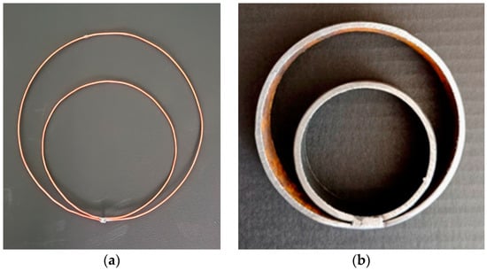
Figure 12.
Laboratory model of a microwave ring resonator: (a) copper; R1 = 95 mm, R2 = 66.5 mm (outer radii), and wire radius r = 0.892 mm (MODEL I); (b) steel; R1 = 45 mm, R2 = 30 mm (outer radii), and wire width = 2 mm (MODEL II).
- (a)
- copper rings R1 = 95 mm, R2 = 66.5 mm (Model I);
- (b)
- steel rings R1 = 45 mm, R2 = 30 mm (Model II).
The ring resonator shown in Figure 12a was used to measure the resonant frequency, while the one shown in Figure 12b was used to measure the transmission coefficients. The measurement, the results of which are shown in Figure 13, was conducted to determine the resonant frequencies of all resonators used in this study: resonators with a single ring, R1 and R2 (Figure 13b), and a ring resonator with eccentric rings (Oo ring eccentric microwave resonator, Figure 13a).
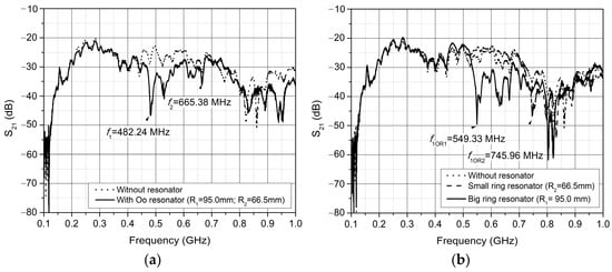
Figure 13.
Measurement of the transmission parameter S21 value for the eccentric ring resonator (MODEL I): (a) Oo ring eccentric microwave resonator; (b) resonators with a single ring, radius R1 and radius R2.
Figure 14 shows that the measured results and the simulation calculations match very well. Variations in the measured results are due to the fact that the measurements were not carried out in a room without electromagnetic resonance, but in a laboratory with many reflections.
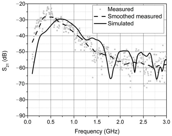
Figure 14.
Measured, measured smoothed, and simulated S21 parameter of the microwave ring resonator (MODEL II).
The measurement results are presented alongside the simulation and analytical calculation results in Table 7 (column *Experimental). The results from all three methods (analytical, simulation, and measurement) correspond very well. Significant deviations occur only in the second mode of the resonator when comparing the analytical calculation with the numerical calculation and measurements. This is likely due to the use of a simplified analytical model that, among other limitations, does not account for capacitive coupling. It should be noted that the analytical calculation was performed prior to the construction of the resonator, serving as a guideline for its implementation. The simulation results obtained using the HFSS application model the resonator much more precisely and accurately, and the final simulation results are closer to the measured values.
Table 7.
Values of calculated (analytical and numerical) and measured resonant frequencies for various resonators.
In addition to determining the resonance frequencies of the individual rings and the annular eccentric resonator both analytically and through simulation, and verifying these results by measurement, measurements and simulation calculations of the transmission coefficient S21 were performed for the derived resonator model with dimensions R1 = 45.0 mm and R2 = 30.0 mm to verify the simulation results.
6. Conclusions
This paper presents an analytical, numerical, and experimental study of a microwave ring resonator composed of two eccentrically coupled conductive rings. Analytical predictions and HFSS simulations identified two resonances at approximately 436 MHz and 708 MHz, which were validated experimentally under laboratory conditions.
The electric field distribution analysis revealed pronounced localization of the E-field within the resonator structure at resonance, with simulated intensities exceeding 170 V/m, while the transmitted field behind the resonator was significantly reduced to below 13 V/m. This strong attenuation confirms the structure’s potential as an effective electromagnetic energy absorber or filter within the sub-1 GHz range. Experimental measurements validated the numerical results, with minor deviations attributed to environmental reflections and model simplifications.
The strong agreement among methods indicates that the proposed configuration can serve as a compact and tunable building block for resonant networks. By adjusting the geometric parameters of the resonator, it is possible to tune this structure for different frequency ranges.
This paper introduces a dual-ring eccentric configuration that expands the attenuation bandwidth below 1 GHz, combining analytical modeling, HFSS simulation, and experimental validation.
Compared to previously reported concentric or symmetrically coupled ring resonators, the proposed eccentric double-ring configuration introduces asymmetric coupling that enables tunable mode interaction, extended attenuation bandwidth, and improved field localization. This distinctive topology provides enhanced control over resonance characteristics without requiring complex multilayer geometries or additional loading materials offering a simpler, more compact, and highly efficient alternative to conventional designs.
The strong correlation between analytical, numerical, and experimental results validates the robustness of the developed model and demonstrates the predictive reliability of eccentric coupling theory. The results establish a new design paradigm for low-frequency resonant structures optimized for electromagnetic shielding, selective absorption, and energy localization applications.
Future research will focus on the implementation of multi-element eccentric resonator arrays, integration into metamaterial composites, and adaptive tuning mechanisms for broadband field control and reconfigurable shielding systems.
Author Contributions
Idea, conceptualization, methodology, writing, resources, S.R. Idea, software, supervising, project administration, V.M. Formal analysis, review, I.B. All authors have read and agreed to the published version of the manuscript.
Funding
Faculty of Electrical Engineering, Computer Science and Information Technology Osijek, project: “System for detecting security threats in a wireless network environment” (acronym: SOS-BMO). This research was funded by the European Union–NextGenerationEU. However, the views and opinions expressed are solely those of the authors and do not necessarily reflect those of the European Union or the European Commission. Neither the European Union nor the European Commission can be held responsible for them.
Institutional Review Board Statement
Not applicable—studies not involving humans or animals.
Informed Consent Statement
Not applicable—for studies not involving humans.
Data Availability Statement
Data is unavailable due to privacy or ethical restrictions.
Acknowledgments
ChatGPT has been used for purposes such as text formatting and study design. During the preparation of this manuscript, the authors used ChatGPT-5.1, Ansys HFSS v221, Inkscape 1.2, Origin2022, and Microsoft Office 15 for the purposes of text formatting, solving problems in electromagnetism, and drawing figures and graphs. The authors have reviewed and edited the output and take full responsibility for the content of this publication.
Conflicts of Interest
The authors declare no conflicts of interest.
References
- Katsarakis, N.; Koschny, T.; Kafesaki, M.; Economou, E.N.; Soukoulis, C.M. Electric Coupling to the Magnetic Resonance of Split Ring Resonators. Appl. Phys. Lett. 2004, 84, 3838–3840. [Google Scholar] [CrossRef]
- Baena, J.D.; Bonache, J.; Martín, F.; Marqués, R.; Falcone, F.; Lopetegi, T.; Laso, M.A.G.; García-García, J.; Gil, I.; Portillo, M.F.; et al. Equivalent-Circuit Models for Split-Ring Resonators and Complementary Split-Ring Resonators Coupled to Planar Transmission Lines. IEEE Trans. Microw. Theory Tech. 2005, 53, 1451–1461. [Google Scholar] [CrossRef]
- Landy, N.I.; Sajuyigbe, S.; Mock, J.J.; Smith, D.R.; Padilla, W.J. A Perfect Metamaterial Absorber. Phys. Rev. Lett. 2008, 100, 207402. [Google Scholar] [CrossRef]
- Shadrivov, I.V.; Morrison, S.K.; Kivshar, Y.S. Tunable Split-Ring Resonators for Nonlinear Negative-Index Metamaterials. Appl. Phys. Lett. 2008, 93, 043518. [Google Scholar] [CrossRef]
- Aydin, K.; Cakmak, O.; Sahin, L.; Li, Z.; Bilotti, F.; Vegni, L.; Ozbay, E. Split Ring Resonator-Coupled Enhanced Transmission through a Single Subwavelength Aperture. Opt. Express 2008, 16, 19850–19861. [Google Scholar] [CrossRef] [PubMed]
- Cheng, Y.; Yang, H.; Cheng, Z.; Wu, N. Perfect Metamaterial Absorber Based on a Split-Ring-Cross Resonator. Appl. Phys. A 2011, 102, 99–103. [Google Scholar] [CrossRef]
- Kapoor, M.; Daya, K.S.; Tyagi, G.S. Coupled Ring Resonator for Microwave Characterization of Dielectric Materials. Int. J. Microw. Wirel. Technol. 2012, 4, 241–246. [Google Scholar] [CrossRef]
- Islam, M.S.; Islam, M.T.; Sahar, N.M.; Rmili, H.; Amin, N.; Chowdhury, M.E.H. A Mutual Coupled Concentric Crossed-Line Split Ring Resonator (CCSRR) Based Epsilon Negative (ENG) Metamaterial for Tri-Band Microwave Applications. Results Phys. 2020, 18, 103292. [Google Scholar] [CrossRef]
- Alahnomi, R.A.; Zakaria, Z.; Yussof, Z.M.; Althuwayb, A.A.; Alhegazi, A.; Alsariera, H.; Rahman, N.A. Review of Recent Microwave Planar Resonator-Based Sensors: Techniques of Complex Permittivity Extraction, Applications, Open Challenges and Future Research Directions. Sensors 2021, 21, 2267. [Google Scholar] [CrossRef]
- Hossain, M.B.; Faruque, M.R.I.; Islam, M.T.; Singh, M.; Jusoh, M. Triple Band Microwave Metamaterial Absorber Based on Double E-Shaped Symmetric Split Ring Resonators for EMI Shielding and Stealth Applications. J. Mater. Res. Technol. 2022, 19, 3483–3492. [Google Scholar] [CrossRef]
- Walsten, A.T.; Dextre, R.A.; Polzin, K.A.; Xu, K.G. Comparison of Single and Concentric Split-Ring Resonator Generated Microplasmas. J. Vac. Sci. Technol. B 2022, 40, 014001. [Google Scholar] [CrossRef]
- Chen, I.-T.; Li, B.; Lee, S.; Chakravarthi, S.; Fu, K.-M.; Li, M. Optomechanical Ring Resonator for Efficient Microwave-Optical Frequency Conversion. Nat. Commun. 2023, 14, 7594. [Google Scholar] [CrossRef]
- Liu, Z.; Duan, J.; Wang, X. Shielding Performance of Electromagnetic Shielding Fabric Implanted with Split-Ring Resonator. Polymers 2023, 15, 1366. [Google Scholar] [CrossRef] [PubMed]
- Rahman, A.A.M.; Islam, M.T.; Rahman, M.M.; Moniruzzaman, M.; Ahmed, F.; Mouti-Guermoud, I. Resonator-Based Near-Perfect Metamaterial Absorber with High EMI Shielding for Wi-Fi and 5G Applications. Int. J. Optomechatronics 2024, 18, 2375497. [Google Scholar] [CrossRef]
- Khouser, G.H.; Choukiker, Y.K. Unique 3D Metamaterial Split Ring Resonator for Wireless Communication with High Negative Refractive Index and for Medium Ratio Waves. Waves Random Complex Media 2022, 32, 3451–3465. [Google Scholar] [CrossRef]
- Masrakin, K.; Ibrahim, S.Z.; Rahim, H.A.; Azemi, S.N.; Soh, P.J.; Tantiviwat, S. Microstrip Sensor Based on Ring Resonator Coupled with Double Square Split Ring Resonator for Solid Material Permittivity Characterization. Micromachines 2023, 14, 790. [Google Scholar] [CrossRef]
- Alibakhshikenari, M.; Virdee, B.S.; Elwi, T.A.; Lubangakene, I.D.; Jayanthi, R.K.R.; Al-Behadili, A.A.; Hassain, Z.A.A.; Ali, S.M.; Pau, G.; Livreri, P.; et al. Design of a Planar Sensor Based on Split-Ring Resonators for Non-Invasive Permittivity Measurement. Sensors 2023, 23, 5306. [Google Scholar] [CrossRef]
- Feng, Y.; Liang, M.; Zhao, X.; You, R. Fabrication and Modulation of Flexible Electromagnetic Metamaterials. Microsyst. Nanoeng. 2025, 11, 14. [Google Scholar] [CrossRef]
- Huq, S.M.I.; Xiao, G.; Bhadra, S. Printed Split Ring Resonator Based Microwave Sensor on Biodegradable Substrate for Dielectric Characterization. Sens. Actuators A Phys. 2025, 393, 116856. [Google Scholar] [CrossRef]
- Islam, M.R.; Islam, M.T.; Hoque, A.; Bais, B.; Alsaif, H.; Islam, M.S.; Soliman, M.S. Quad-Band Split Ring Resonator-Based Sensor for Microwave Sensing Application. Sci. Rep. 2025, 15, 6888. [Google Scholar] [CrossRef] [PubMed]
- Rabbani, M.G.; Islam, M.T.; Moniruzzaman, M.; Alamri, S.; Rahman, A.A.M.; Moubark, A.M.; Islam, M.S.; Soliman, M.S. Dumbbell-Shaped Structure Loaded Modified Circular Ring Resonator Based Perfect Metamaterial Absorber for S, X and Ku-Band Microwave Sensing Applications. Sci. Rep. 2024, 14, 5588. [Google Scholar] [CrossRef] [PubMed]
- Jahan, M.I.; Ullah, M.; Ahmad, H.; Roslan, R.; Misnon, I.I.; Jose, R. Two Split Rings Resonator-Based Perfect Metamaterial Absorbers with Incident and Polarization Angle Independence for Sensing Applications. J. Magn. Magn. Mater. 2024, 594, 171904. [Google Scholar] [CrossRef]
- Devoret, M.H. Quantum Fluctuations in Electrical Circuits. Elsevier Sci. 1997, 63, 351–386. [Google Scholar]


Disclaimer/Publisher’s Note: The statements, opinions and data contained in all publications are solely those of the individual author(s) and contributor(s) and not of MDPI and/or the editor(s). MDPI and/or the editor(s) disclaim responsibility for any injury to people or property resulting from any ideas, methods, instructions or products referred to in the content. |
© 2025 by the authors. Licensee MDPI, Basel, Switzerland. This article is an open access article distributed under the terms and conditions of the Creative Commons Attribution (CC BY) license (https://creativecommons.org/licenses/by/4.0/).