1. Introduction
Light field displays [
1,
2,
3,
4,
5] generate three-dimensional (3D) images by reconstructing light rays from 3D objects, allowing observers to view them without glasses or other devices. Flat-panel-type light field displays, implemented by combining a liquid crystal display or organic light-emitting diode display [
6] with optical elements such as lens or aperture arrays [
7,
8,
9], have enabled practical 3D display applications due to their thin structure. However, conventional flat-panel-type light field displays suffer from a narrow viewing zone, low light efficiency, low resolution, and moiré artifacts. To address these issues, near-virtual-image-mode light field displays with enhanced viewing zones, increased light efficiency, and high resolution have been developed [
10,
11]. In this study, we propose a technique to resolve the moiré problem in the flat-panel-type light field displays.
Near-virtual-image-mode light field displays employ both lens and aperture arrays. The lens array forms virtual images of pixels located behind the display plane, expanding the viewing-zone angle compared with conventional lens-array-type light field displays. Similar to conventional aperture-array-type light field displays, the aperture limits the number of virtual pixel images seen through it to one, thereby reducing crosstalk. Because the aperture width is equal to the width of the enlarged virtual pixel image, near-virtual-image-mode light field displays achieve higher light efficiency than conventional aperture-array-type light field displays, where the aperture width equals the pixel pitch. Additionally, a technique to enhance the resolution of the near-virtual-image-mode light field displays involves reducing the magnification of virtual pixel images so that multiple virtual images can be viewed through a single lens of the lens array.
However, moiré artifacts on the display surface disrupt the 3D perception of observers. In light field displays, these artifacts are typically caused by differences in spatial frequency between the pixel structure and the lens or aperture array [
12,
13] (e.g., mismatch between the pitches of the pixel and lens). In contrast, in the near-virtual-image mode, the moiré artifacts essentially arise from the periodic distortion of the virtual subpixel images induced by the nonrectangular pixel structure of the flat-panel display. This study specifically addresses moiré artifacts caused by pixel structures in the near-virtual-image-mode light field displays.
Several moiré reduction techniques have been proposed for light field displays. Techniques have been proposed to suppress moiré by the use of diffusers and lens defocusing to attenuate low spatial frequencies. Diffusers scatter light rays to suppress low-frequency image components [
14,
15]. Lens defocusing alters the distance between the display and the lens array to reduce moiré artifacts [
16]. However, these techniques produce blurred 3D images. Analytical methods have also been developed to determine the optimal pitch and slanted angles of the lens or aperture arrays by analyzing moiré patterns. By geometrically approximating the superposition of the display and lens array as four superimposed sine gratings, these methods identify the conditions for minimizing moiré through lens slanted angles [
17]. In the case of the aperture array, optimal aperture pitch and slanted angle have been studied by modeling apertures as binary gratings to minimize moiré artifacts [
18]. Moiré patterns have also been analyzed using visualization methods that calculate subpixels selected by lens arrays to determine the optimal slanted angle [
19,
20]. However, these analytical methods assume rectangular pixel shapes. Because the proposed near-virtual-image-mode light field displays use liquid crystal displays with various nonrectangular pixel shapes, it is necessary to analyze the moiré in consideration of the pixel shapes.
Recently, a technique was proposed to suppress moiré by providing zigzag shapes to the apertures in aperture-array-type light field displays, which reduces interference between high-frequency components of the apertures and pixels [
21]. Introducing unevenness into slit apertures allows them to act as Gaussian low-pass filters. We apply the idea of modifying the aperture shape of the aperture array to the near-virtual-image-mode light field displays to suppress high-frequency components arising from the pixel structure. To apply the zigzag apertures to the near-virtual-image mode, we modified the design such that the zigzag aperture shape matches the subpixel geometry of the liquid crystal display. Compared with diffuser-based techniques, this aperture-deformation approach may suppress blur in 3D images.
In this study, we apply the moiré reduction technique by modifying the aperture shape in the aperture arrays of the near-virtual-image-mode light field displays. The aperture shape is designed using a diffraction-based moiré analysis we developed. In the near-virtual-image mode, moiré artifacts arise from the deformation of virtual subpixel images due to nonrectangular pixel shapes. Therefore, diffraction calculations are used to obtain the intensity distribution of virtual subpixel images generated by light of nonrectangular pixels through the aperture and lens arrays.
The remainder of this paper is organized as follows.
Section 2 explains the near-virtual-image-mode light field displays and the origin of moiré artifacts.
Section 3 describes the proposed moiré reduction technique.
Section 4 presents diffraction-based moiré simulations and results. Experimental results are presented in
Section 5, followed by a discussion in
Section 6.
Section 7 concludes the paper.
2. Occurrence of Moiré Artifacts on Near-Virtual-Image-Mode Light Field Displays
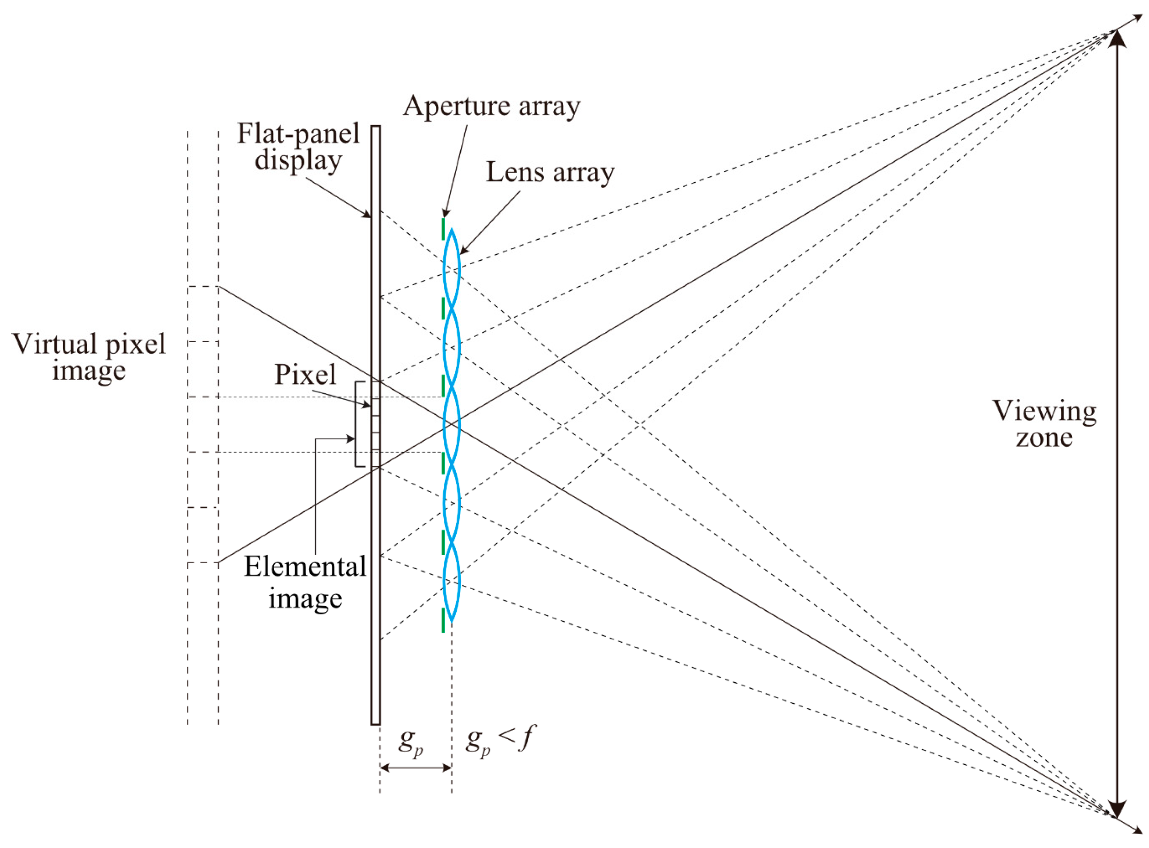
Figure 1 shows the configuration of the previously proposed near-virtual-image-mode light field display [
10] comprising a flat-panel display, a lens array, and an aperture array. In conventional lens-array-type light field displays, the flat-panel display is located near the focal length of the lens array (
f). In the near-virtual-image mode, the distance between the flat-panel display and lens array (
gp) is smaller than
f; as a result, the viewing zone is enlarged compared with that offered by conventional lens-array-type light field displays, where
gp =
f. In this case, the lens makes virtual images of the pixels of the flat-panel display behind the display plane. A magnification of the pixel is adjusted such that the width of the virtual pixel image is narrower than the lens pitch of the lens array. The aperture array is used to allow only one virtual pixel image to be observed through a single lens of the lens array, thereby reducing crosstalk. Although the aperture width needs to be equal to the pixel pitch in aperture-array-type light field displays, it is equal to the pitch of the virtual pixel image in near-virtual-image-mode light field displays. Therefore, the near-virtual-image-mode light field displays have higher light efficiency than the conventional aperture-array-type light field displays. Furthermore, a resolution improvement technique was proposed, which allowed multiple virtual pixel images to be seen through a single aperture by further reducing the magnification of the pixels [
11].
However, moiré fringes appear on the display surface when a high-resolution flat-panel display is used in near-virtual-image-mode light-field displays. Recently developed high-resolution flat-panel displays contain nonrectangular pixel shapes to improve viewing angles [
22,
23]; however, these pixel structures are problematic for near-virtual-image-mode light field displays.
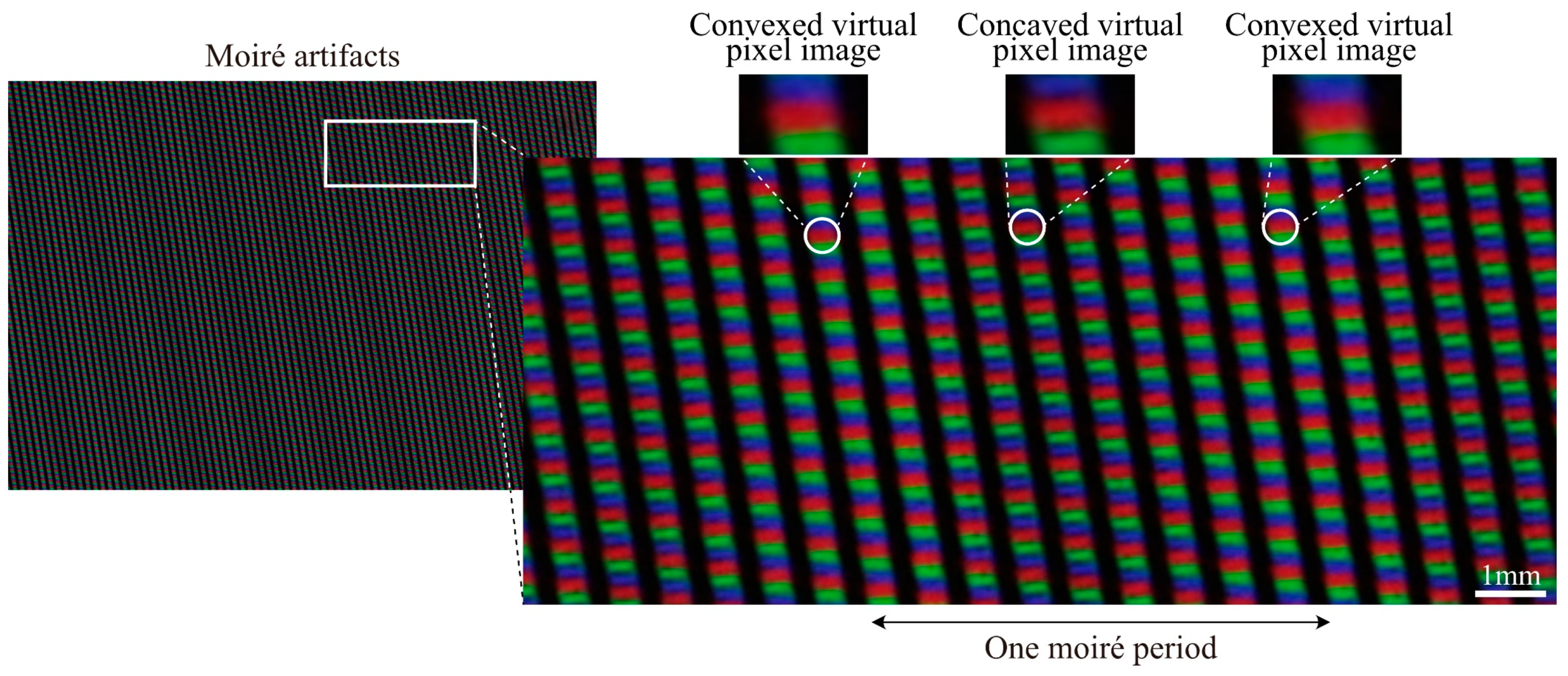
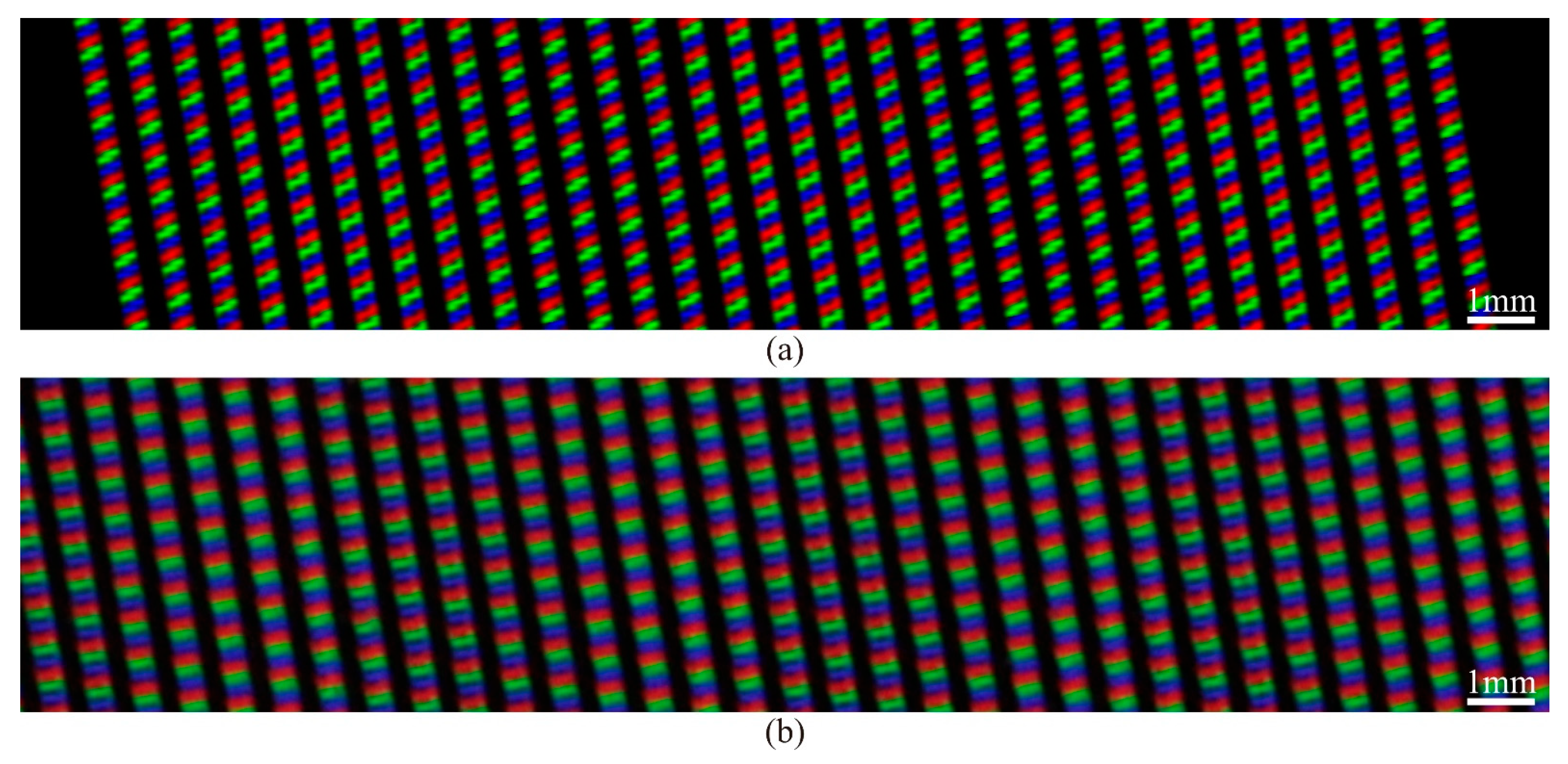
Figure 2 shows an enlarged image of moiré fringes when a white image is displayed on the light field display. The moiré fringes were captured using a single-lens reflex (SLR) camera (Canon, Tokyo, Japan) equipped with a 250 mm lens positioned 1.2 m away from the display surface. The virtual images of subpixels were observed through a lenticular lens, and the shapes of virtual subpixel images were periodically changed in the horizontal direction. At the center area of the figure, virtual subpixel images with a concave shape are visible and convex-shaped images are observed in the neighboring area. This deformation of virtual pixel images continues periodically in the entire display, resulting in spatial fluctuations in the perceived light intensity. Consequently, these distortions of the virtual subpixel images are considered to primarily generate moiré fringes in the near-virtual-image-mode light field display. The deformation period was estimated by identifying repeating shapes of virtual pixel images, which extended over approximately 10 cylindrical lenses.
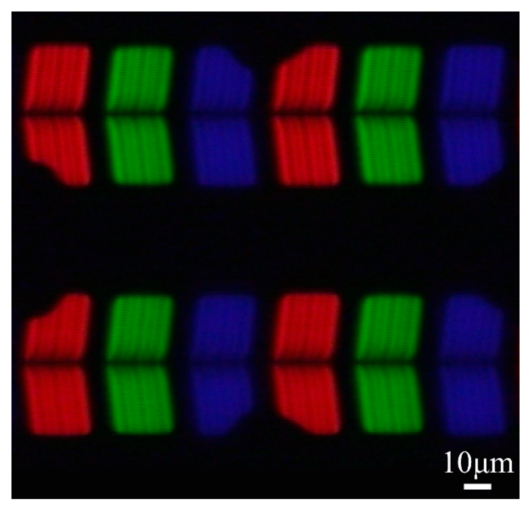
Figure 3 shows the magnified image of the periodic subpixel structure of liquid crystal displays used in near-virtual-image-mode light field displays. The display comprises two types of R-subpixel shapes, two types of B-subpixel shapes, and one type of G-subpixel shape. As these different subpixel shapes repeat periodically, the aforementioned virtual pixel image deformation occurs.
3. Proposed Moiré Reduction Technique
We propose the moiré reduction technique for near-virtual-image-mode light field displays by reducing the periodic deformation of virtual subpixel images. This is achieved by changing the aperture shape of the aperture array from straight to sophisticated shapes, suppressing differences in the subpixel shapes of flat-panel displays.
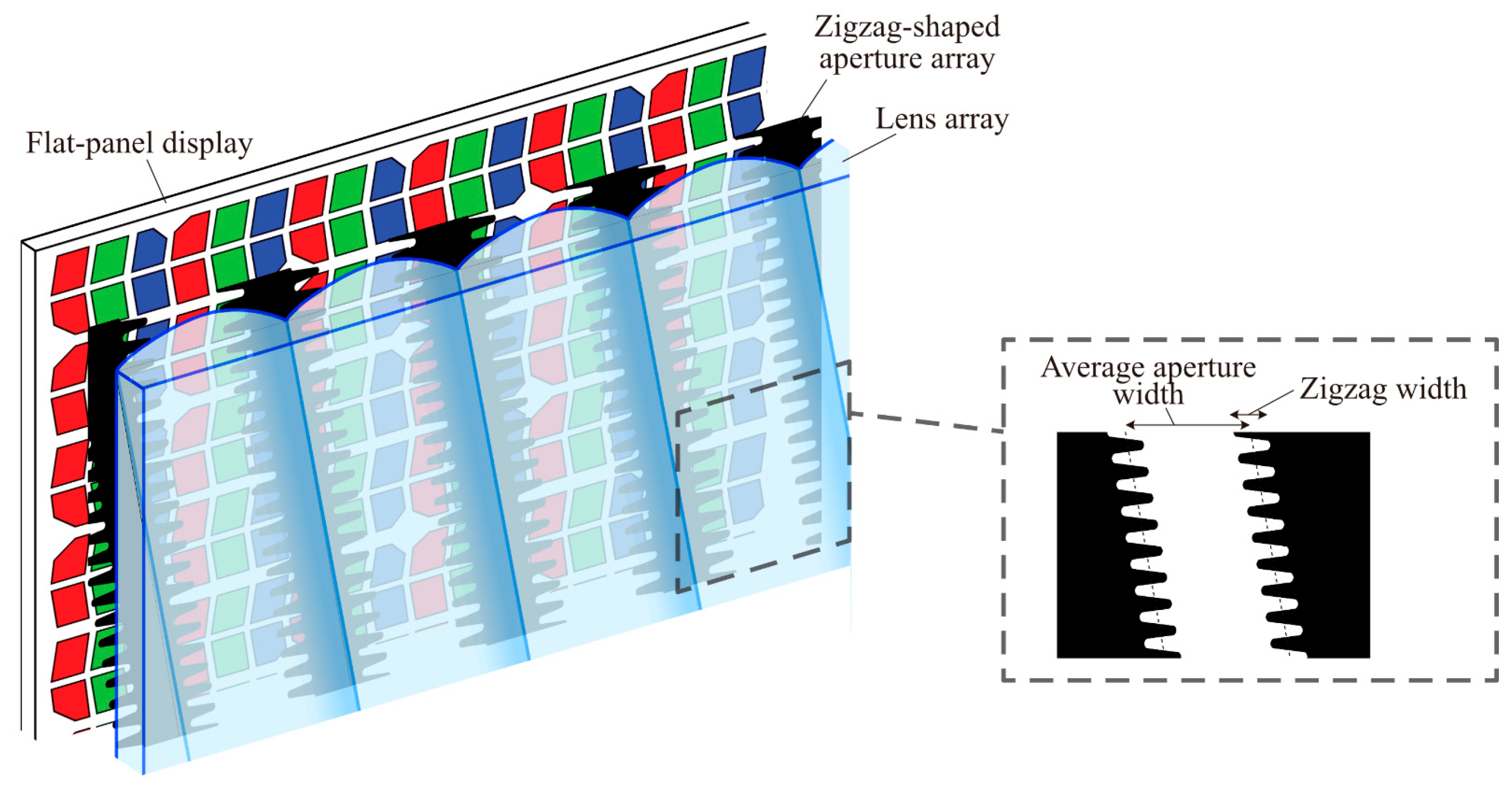
Figure 4 shows the configuration of the moiré-reduced light field display in near-virtual-image mode. The zigzag-shaped aperture array and lenticular lens are placed in front of the flat-panel display. As shown in
Figure 3, differences in RGB pixel shapes exist only in the peripheral regions of the pixels. The zigzag shape of the aperture array reduces these peripheral differences in the subpixel shapes, while not influencing light rays from the centers of the subpixels. By suppressing differences in subpixel shapes, the periodic changes in virtual pixel images are moderated, thereby minimizing moiré artifacts.
Unlike conventional moiré reduction techniques that rely on blurring via diffusers [
14,
15] or lens defocusing [
16], the proposed technique blurs the subpixel structures using the apertures. Date et al. [
21] also proposed a moiré reduction technique by deforming the aperture shape in light field displays. We applied this approach to near-virtual-image-mode light field displays using a zigzag aperture. The difference between the technique by Date et al. [
21] and ours is that the former determines the parameters of the zigzag aperture using a Gaussian function, whereas our technique determines the parameters based on the subpixel geometry. The near -virtual-image-mode light field displays employ both the lens and aperture arrays, and the proposed technique gives the role of suppressing moiré to the aperture array, which was originally used to limit ray divergence.
The design scheme of the zigzag apertures is described. The zigzag width and average aperture width are defined as shown in
Figure 4. The zigzag width is determined based on differences in the horizontal shape of the virtual images formed by RGB subpixels. In near-virtual-image mode, one virtual subpixel image is seen through each aperture, so the average aperture width is set equal to the pitch of the virtual subpixel images. Vertically, the pitch of the zigzag pattern is smaller than the vertical pitch of the subpixels.
4. Simulations
The zigzag aperture was designed using the diffraction-based moiré analysis [
24,
25].
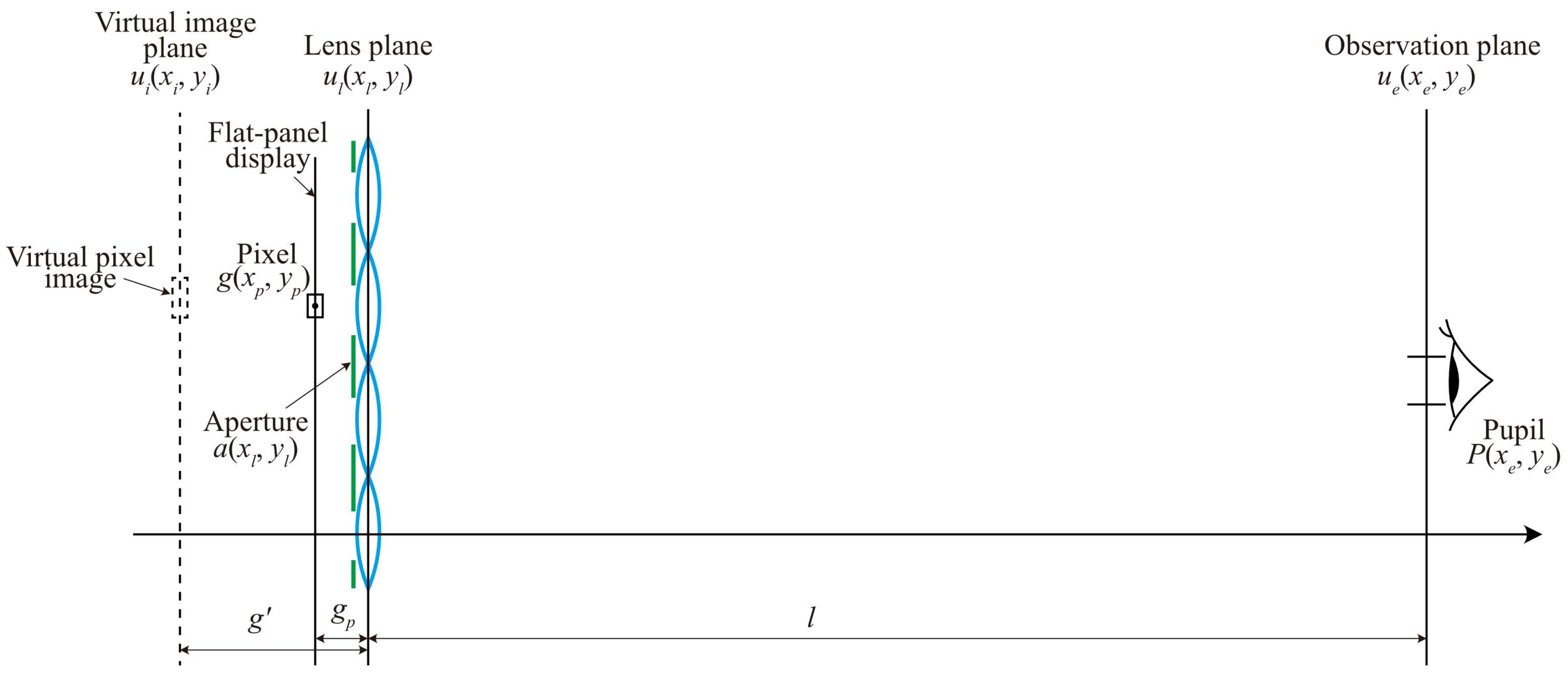
Figure 5 shows computational planes and parameters for diffraction-based moiré analysis. First, the propagation of a spherical wave from a single point on a pixel to an aperture and lens is calculated. The complex amplitude distribution of the spherical wave at the lens plane, denoted by
ul(
xl,
yl), is obtained as follows:
where
g(
xp,
yp) is the pixel intensity,
U(
xl,
yl) is the phase distribution of the spherical wave,
a(
xl,
yl) is the aperture shape, and
ϕl is the phase distribution of lens. Then, light propagation from the lens plane to the observation plane is calculated via Fresnel diffraction. The distribution at the observation plane, denoted by
ue(
xe,
ye), can be expressed as follows:
where FT denotes the Fourier transform,
λ is a wavelength, and
l is the distance between the lens plane and observation plane. On the observation plane, the distribution is clipped by the pupil of an eye to obtain the image perceived by the observer’s eye. Inverse Fresnel diffraction is applied to the clipped distribution to reconstruct the image at the virtual image plane focused on by the eye. The resultant image from the single point on the subpixel seen by the observer,
ui(
xi,
yi), is given by
where IFT denotes the inverse Fourier transform,
P(
xe,
ye) is the eye pupil function, and
g′ is the distance between the lens and virtual image planes. These calculations are performed for all points within a subpixel to obtain a single virtual subpixel image. Finally, virtual subpixel images are calculated for all subpixels and added to generate the moiré image.
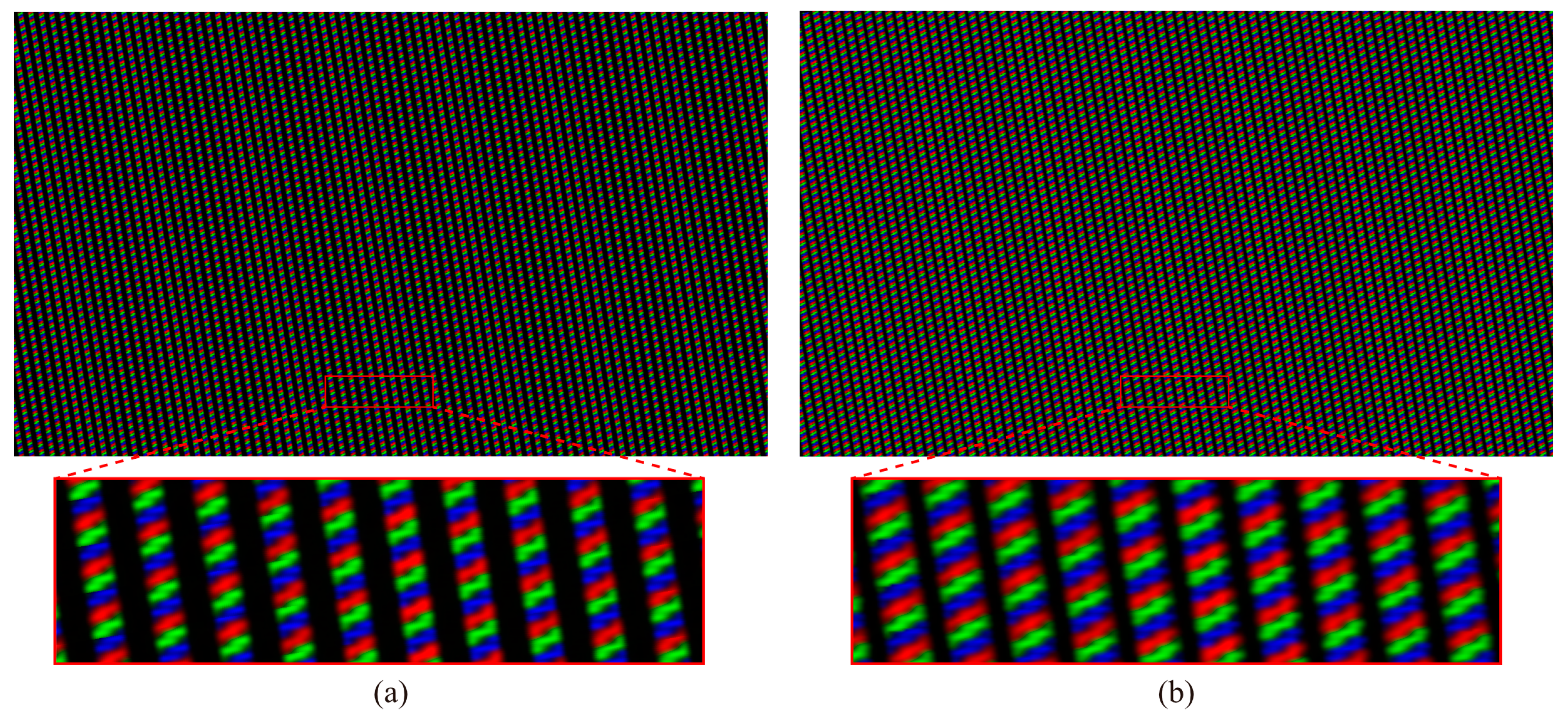
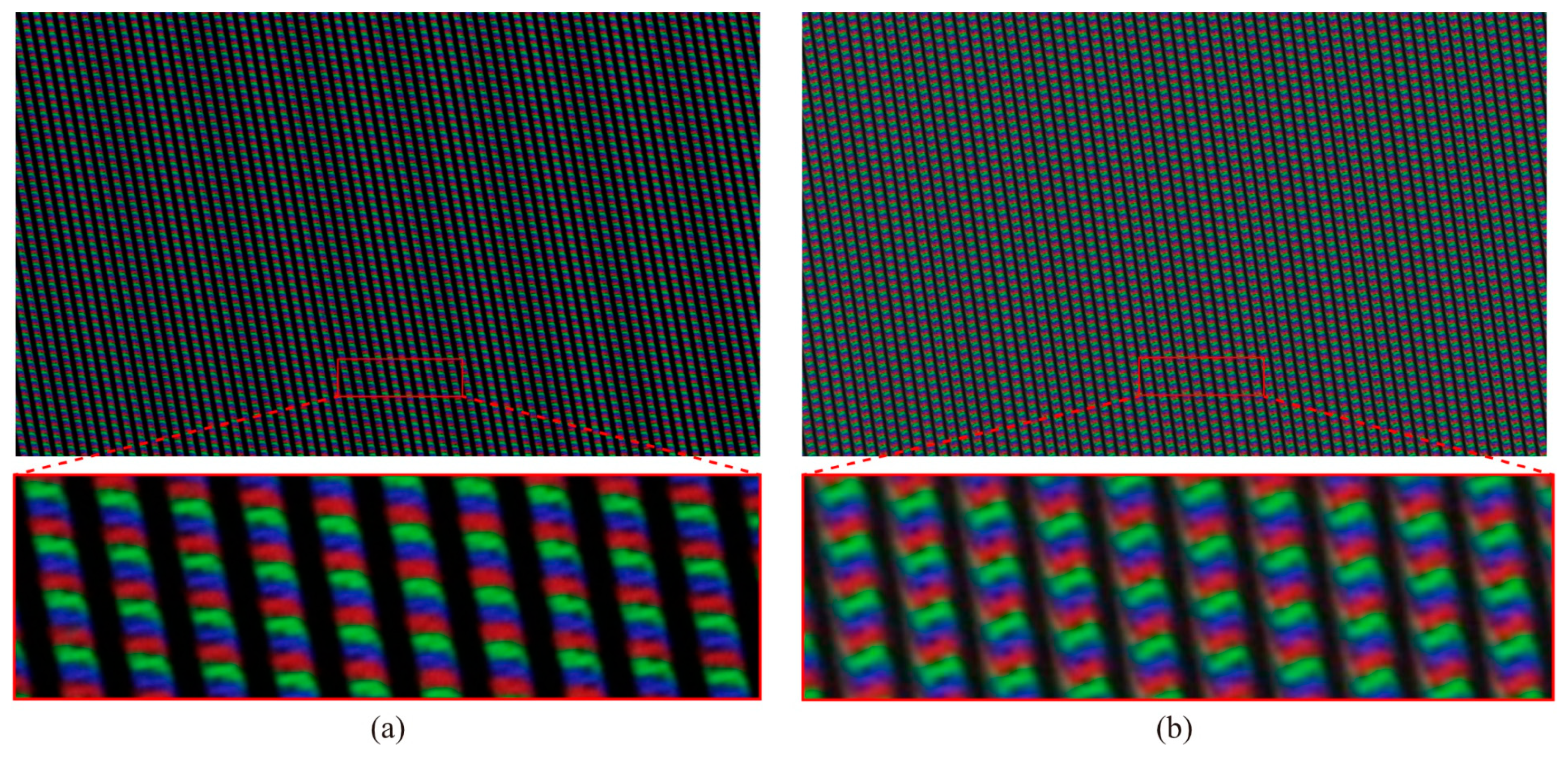
Figure 6a shows the simulated moiré image obtained by calculating the diffraction for the pixel structure shown in
Figure 3. The simulation result provides three moiré periods. This image shows periodic deformations in virtual subpixel images akin to those observed in the captured image shown in
Figure 6b. The captured image appears more blurred than the simulated image because calculations were conducted for only a single wavelength in each RGB subpixel during the simulation. We use this diffraction-based moiré analysis to calculate the contrast of moiré and evaluate the design of zigzag apertures.
In this simulation, the zigzag aperture was designed for the prototype of the near-virtual-image-mode light field displays with horizontal parallax developed in Ref. [
9]. A lenticular lens and a slit array were used for the lens and aperture arrays, respectively. The lens pitch and focal length of the lenticular lens were 0.699 and 0.953 mm, respectively. The lenticular lens was slanted at 9.46° to balance the horizontal and vertical 3D resolutions [
26]. The flat-panel display was an 8K liquid crystal display from Dell (Austin, TX, USA), which is the same display as shown in
Figure 3. The pixel and subpixel pitches of the flat-panel display were 0.0909 and 0.0303 mm, respectively. The distance between the display and lens plane was 0.883 mm, and that between the lens plane and observation plane was 1200 mm. The pitch of the virtual pixel images was 0.413 mm.
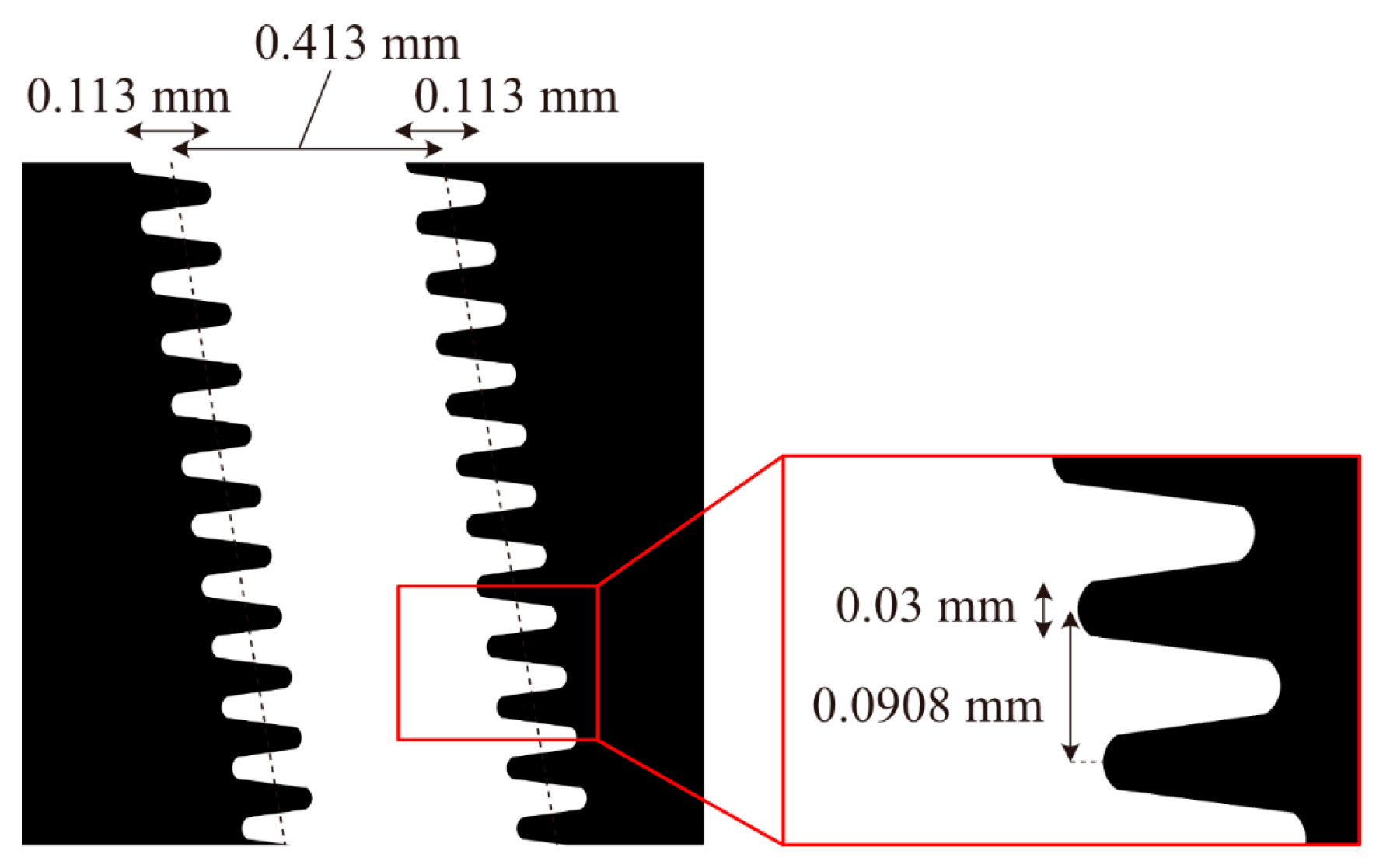
Figure 7 shows the designed zigzag slit. The zigzag width was determined by measuring the differences in the horizontal shapes of the virtual subpixel images considering the liquid crystal display shown in
Figure 3 and setting it equal to their average value. As a result, the zigzag width was 0.113 mm, and the average aperture width was 0.413 mm. As a film-based photomask was used for the slit array, we had to follow the requirement in the fabrication process that the minimum line width was limited to 0.03 mm. Therefore, the sharp tips of zigzag shapes were rounded to meet the requirement. The vertical pitch of the zigzag pattern was set to 0.0908 mm, equal to the pixel pitch obtained after considering the vertical parallax. The zigzag slit was slanted at the same angle as the lenticular lens. For comparison, moiré artifacts were simulated using a straight slit without zigzag shapes, which corresponds to the conventional aperture shapes used in the previous prototype. The aperture width of the straight slit was determined from the prototype we previously developed [
10] as 0.355 mm. The straight slit was also slanted at the same angle for the lenticular lens.
Figure 8 shows the simulation results obtained using straight and zigzag slits, along with enlarged pictures of one moiré period at a magnification factor of six. The simulation results were calculated considering distance
l = 1.2 m and a pupil diameter of 7.8 mm. Compared with the straight slit, the deformation of virtual subpixel images was moderated by the zigzag slit. As shown in
Figure 8a, the straight slit caused periodic light intensity changes in the horizontal direction and generated moiré artifacts. In contrast, the zigzag slit weakened the moiré in
Figure 8b. The period of moiré artifacts was approximately 10 lenses in both results, corresponding to the results discussed in
Section 2.
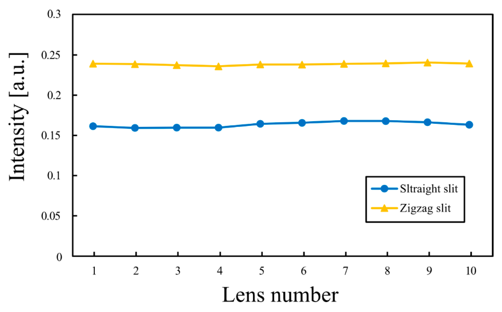
Figure 9 shows the light intensities of virtual subpixel images obtained from the specific regions indicated in
Figure 8. These values were obtained by averaging the intensities of the virtual pixel images aligned vertically along the cylindrical lens, excluding the black regions of the aperture. The intensity variation for the zigzag slit was smaller than that for the straight slit. The moiré contrast was calculated using the light intensities shown in
Figure 9 as follows:
where
Imax and
Imin denote the maximum and minimum light intensities within one moiré period, respectively. The moiré contrast was 0.0263 for the straight slit, whereas it decreased to 0.00916 for the zigzag slit. The average intensity was 0.164 for the straight slit and 0.240 for the zigzag slit. These simulation results confirmed that the designed zigzag slit could suppress moiré patterns in near-virtual-image-mode light field displays.
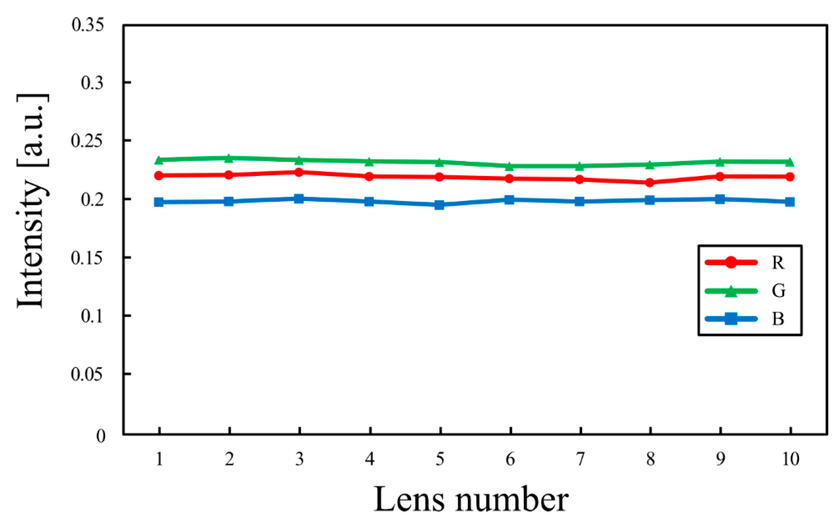
Figure 10 shows the RGB light intensities for the zigzag slit in the simulation results over one moiré period. Although the block size by zigzag patterns differed slightly across RGB subpixels, the intensity fluctuations were uniformly suppressed. While the absolute intensity differences across the red, green, and blue channels persisted, they could be compensated by adjusting the display intensity.
5. Experiments
The moiré reduction in the proposed technique using zigzag slits was validated experimentally on near-virtual-image-mode light field display described in
Section 4.
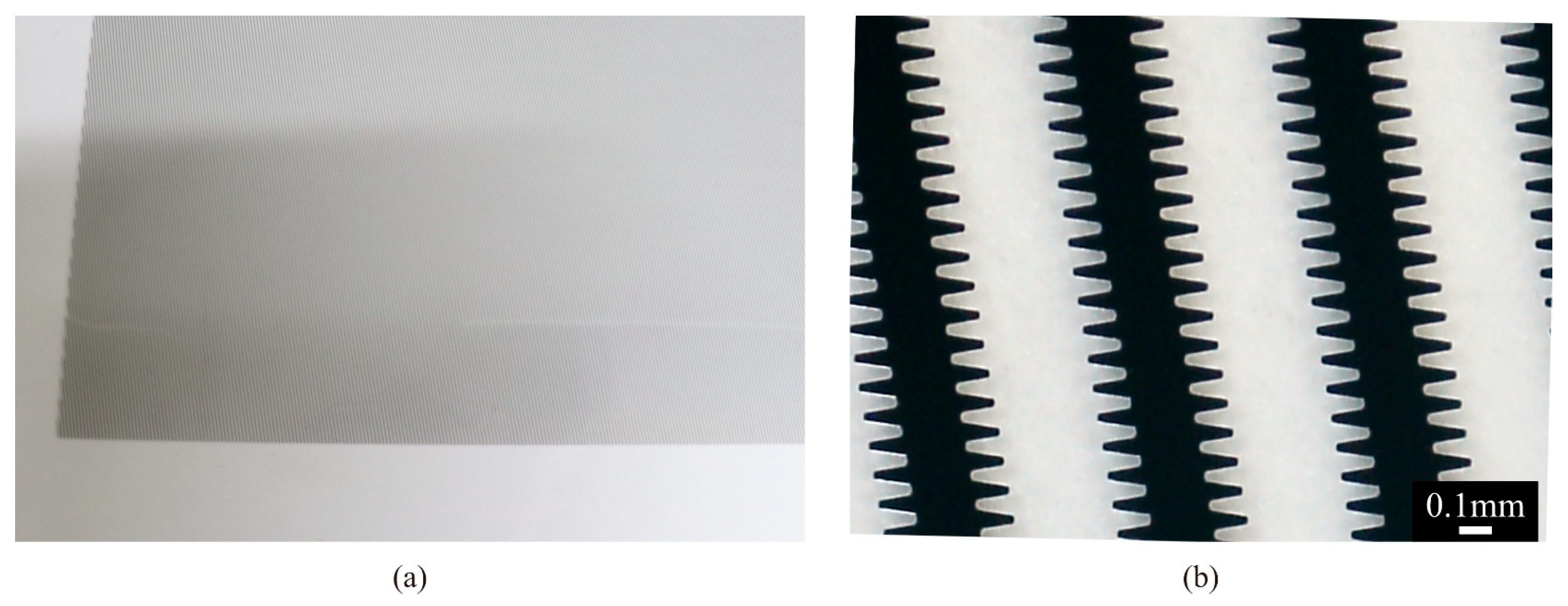
Figure 11 shows the fabricated zigzag slit film. The measured zigzag width and average aperture width were 0.114 and 0.413 mm, respectively, closely matching the designed values.
Figure 12 presents the experimental results obtained by displaying a white image on the light field display using straight and zigzag slits. The moiré images were captured at 1.2 m from the display surface using an SLR camera with a pupil size of 7.8 mm. Enlarged pictures of one moiré period under magnification with a factor of six are also shown. The deformation of virtual subpixel images was also suppressed. Compared with straight slits, zigzag slits reduced moiré artifacts. The measured moiré periods were approximately 10 lenses in both cases.
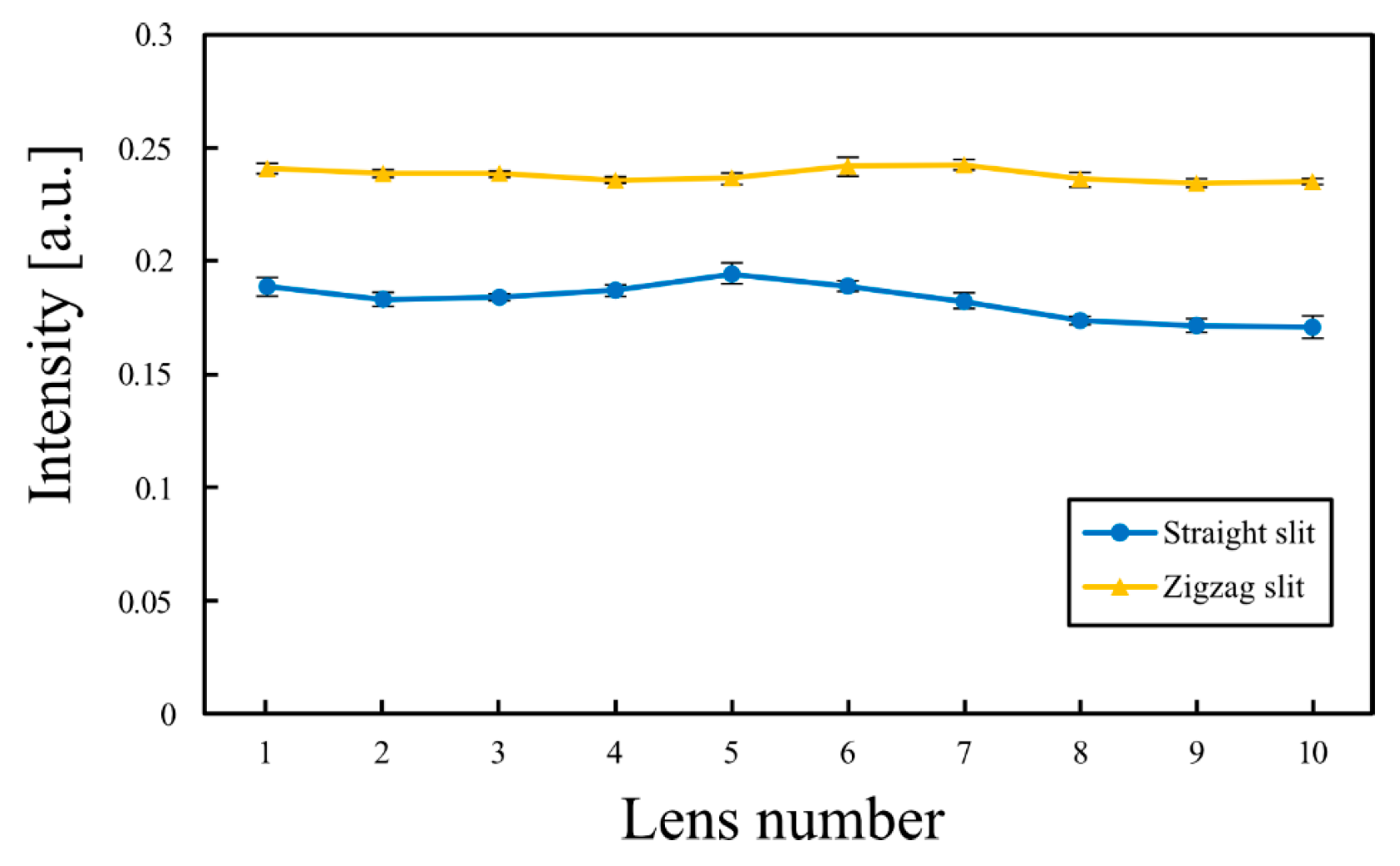
Figure 13 shows the measured light intensities of virtual subpixel images for one moiré period, as indicated in
Figure 12. The intensities are shown as averages over five trials, and the error bars indicate the standard deviations. The intensity variation for the zigzag slit was smaller than that for the straight slit. From the light intensities in
Figure 13, the moiré contrast was calculated as 0.0639 for the straight slit and 0.0169 for the zigzag slit, demonstrating that zigzag slits effectively reduced moiré contrast. The average intensity was 0.183 for the straight slit and 0.238 for the zigzag slit, reflecting the increased aperture width in light field displays with zigzag slits.
Figure 14 shows 3D images of a human upper body displayed using the straight and zigzag slits. The 3D model was generated by capturing an actual person with a depth camera and an RGB camera.
Figure 14 includes enlarged images at the cheek regions of the 3D images. While
Figure 12 shows a region of the display screen with clear moiré pattern reduction,
Figure 14 shows the entire display screen. Whereas moiré artifacts were observed with straight slits in
Figure 14a, they were generally reduced when using zigzag slits. However, as shown in
Figure 14b, the moiré pattern was particularly noticeable in some areas, such as the right cheek, neck, and hoodie. These residual moiré artifacts likely occurred because the display panel, slit array, and lenticular lens were not adhered together. In these regions, the gap between the lens array and display increased slightly, altering the magnification of the virtual subpixel images and undermining the suppression of moiré artifacts. By adhering the display panel, slit array, and lenticular lens together, the moiré effect could be mitigated. Furthermore, at the edges of the screen (background regions), the moiré effect with zigzag slits was more severe than that with straight slits because of slight misalignments between the lens and aperture arrays.
6. Discussion
The designed zigzag slits yielded lower moiré contrast compared with the conventional straight slits. The minimum contrast perceivable by the human eye depends on spatial frequency and retinal illuminance level [
27]. In the experiment, the spatial frequency of the moiré fringe and retinal illuminance were measured as 3.41 cycles/degree and 1910 Td, respectively, corresponding to a theoretical minimum contrast perceivable by the human eye of 0.0020. Moiré artifacts with contrast below this value were assumed to be imperceptible. The measured moiré contrast reduced by varying degrees, from a factor of 32 compared with the minimum contrast for straight slits to a factor of 8.5 higher for the zigzag slit. However, it remained above the minimum value. In the simulation results, the moiré contrast of the zigzag slit also exceeded the threshold, suggesting the difficulty to reduce the moiré contrast below an imperceptible level when using the zigzag slits for a flat-panel display with the nonrectangular pixels considered in this study. To further reduce the moiré contrast, displays with more uniform subpixel geometries may be required.
Figure 15a,b shows the RGB light intensities obtained for the zigzag and straight slits, respectively, over one moiré period. The range of RGB intensity variations was smaller for the zigzag slit than for the straight slit. The moiré contrasts for each RGB in the zigzag slit were 0.0114, 0.0197, and 0.0225, respectively, whereas those for the straight slit were 0.786, 0.633, and 0.486, respectively. These results indicate that the zigzag slit reduced each moiré contrast in RGB, revealing that the proposed technique also suppressed the color moiré. The absolute intensity differences across RGB channels were mainly attributed to the white balance setting of the camera used for measurement.
The tolerance of the film-based photomask technique is discussed. According to the fabrication specifications, the tolerance of the line pattern was ±3 μm. For the designed zigzag aperture shape, the zigzag width might vary by ±3 μm compared with the virtual subpixel width of 0.34 mm. The simulation results indicated moiré contrasts of 0.00569 and 0.0129, when the zigzag width increased and decreased by 3 μm, respectively. Although the tolerance of the film-based fabrication process altered moiré suppression using zigzag apertures, its impact on moiré suppression was limited.
