Review

Review of Approaches to Creating Control Systems for Solid-State Transformers in Hybrid Distribution Networks

by
Pavel Ilyushin
1,*,
Vladislav Volnyi
1 and
Konstantin Suslov
2,3
1
Department of Research on the Relationship Between Energy and the Economy, Energy Research Institute of the Russian Academy of Sciences, 117186 Moscow, Russia
2
Department of Hydropower and Renewable Energy, National Research University “Moscow Power Engineering Institute”, 111250 Moscow, Russia
3
Department of Power Supply and Electrical Engineering, Irkutsk National Research Technical University, 664074 Irkutsk, Russia
*
Author to whom correspondence should be addressed.
Appl. Sci. 2025, 15(20), 10970; https://doi.org/10.3390/app152010970
Submission received: 19 September 2025 / Revised: 9 October 2025 / Accepted: 11 October 2025 / Published: 13 October 2025
(This article belongs to the Section Energy Science and Technology)

Abstract

Large-scale integration of distributed energy resources (DERs) into distribution networks causes topological-operational situations with multidirectional power flows. One of the main components of distribution networks is the power transformer, which does not have the capabilities for real-time control of distribution network parameters with DERs. The use of solid-state transformers (SSTs) for connecting medium-voltage (MV) and low-voltage (LV) distribution networks of both alternating and direct current has great potential for constructing new distribution networks and enhancing the existing ones. Electricity losses in distribution networks can be reduced through the establishment of MV and LV DC networks. In hybrid AC-DC distribution networks, the SSTs can be especially effective, ensuring compensation for voltage dips, fluctuations, and interruptions; regulation of voltage, current, frequency, and power factor in LV networks; and reduction in the levels of harmonic current and voltage due to the presence of power electronic converters (PECs) and capacitors in the DC link. To control the operating parameters of hybrid distribution networks with solid-state transformers, it is crucial to develop and implement advanced control systems (CSs). The purpose of this review is a comprehensive analysis of the features of the creation of CSs SSTs when they are used in hybrid distribution networks with DERs to identify the most effective principles and methods for managing SSTs of different designs, which will accelerate the development and implementation of CSs. This review focuses on the design principles and control strategies for SSTs, guided by their architecture and intended functionality. The architecture of the solid-state transformer control system is presented with a detailed description of the main stages of control. In addition, the features of the SST CS operating under various topologies and operating conditions of distribution networks are examined.

1. Introduction

Digital transformation of electric power systems facilitates introducing new mechanisms for interaction among different entities within the electric power industry [1,2]. The implementation of advanced technical solutions boosts the reliability and efficiency of the medium- and low-voltage distribution networks incorporating DER [3,4,5]. At the same time, there is a simultaneous transformation of consumers into prosumers who actively participate in managing the operation of the medium- and low-voltage distribution networks. This becomes possible due to the decentralization of generation capacities, which arises from consumers’ adoption of their diverse distributed self-generation systems [6].
Distributed energy resources encompass fuel-based distributed energy facilities, facilities based on renewable energy sources (RESs), energy storage systems (ESSs), and controlled load [7,8]. Their construction enables various consumers (industrial, commercial, and residential) to ensure a reliable power supply in the event of accidents in external distribution networks [9,10,11].
Some DERs are preferable for integration into DC networks, which makes the construction of hybrid AC-DC distribution networks effective [12,13,14]. However, this requires the development of new technical requirements and principles for the construction of MV and LV distribution networks to incorporate DERs [15,16,17]. The widespread use of public and private electric transport is another incentive to establish DC networks. Programs designed to stimulate the transition to electric transport provide for the development of electric charging infrastructure for fast and slow charging, using intelligent control algorithms that ensure optimal loading of distribution networks [18,19].
The integration of heterogeneous DER into distribution networks causes their vertical structure to transform into a horizontal one and leads to multidirectional power flows. Passive distribution networks were not designed to operate in such landscapes [20,21].
Power transformers provide electrical energy conversion and nexus among different voltage classes in the distribution network. They operate at a frequency of 50 Hz and have limited ranges of voltage regulation under load (on-load tap changer—OLTC) ±16% or without load (no-load tap changer—NLTC) ±5% [22,23]. An important requirement for power transformers is the expansion of the capabilities for controlling the power flow parameters in distribution networks, i.e., the functions of voltage, current, and frequency regulation [24]. The degree of controllability is determined by the operating conditions and the purpose of power transformers. In this case, it is normally sufficient to implement one of the control functions to accomplish the set task [25].
When shifting from passive electrical energy transformation (OLTC/NLTC power transformers) and transitioning to the active distribution networks, it is essential to ensure voltage, current, and frequency regulation across wide ranges. This can be achieved utilizing solid-state transformers, which include high power electronic converters [26,27].
Widespread implementation of smart grid technologies in active distribution networks with DER, through the use of digital systems for monitoring, diagnostics, condition assessment, protection, and control, provides the maximum possible technical and economic effects [28].
The paper aims to present a review of the design principles and control approaches for solid-state transformers, which are determined by their architecture and intended application. The main stages of SST control are also explored, and the features of the SST control systems functioning under various topologies and operating conditions of hybrid distribution networks are identified.
Existing studies consider SSTs as an interface for connecting DERs to a hybrid distribution network, revealing positive effects from the implementation of SSTs. Scottish Power Energy Networks [29] notes that the use of 400 V LV DC networks based on SSTs will achieve savings of up to £62 m by 2030 and £528 m by 2050. In [30], it is shown that the integration of DERs through SSTs in the amount of 33% of the total capacity will reduce energy losses by up to 26%. These and other studies do not consider the design of SSTs, nor their impact on the selection of CSs. Analysis of the impact of SST configurations on the area of their application will reduce the cost of SSTs compared to other devices and control strategies for hybrid AC-DC distribution networks [31].
This review presents the results of an analysis of various SST design variants, as well as the design principles and control methods used to create CS SSTs based on multiple active bridges, simplified to dual active bridges. This approach allows for the optimization of SST configurations depending on the type of distribution network and the determination of CS performance requirements.
The review is structured as follows. Section 2 focuses on the main features of active distribution networks with DER, analyzing the generalized structure of SST and the current issues resolved with SST. Section 3 explores the main SST topologies that are most effective for use in distribution networks with DER. Section 4 presents the results of analyzing the SST control principles and module connection diagrams, as well as the coordinated architecture of the control system of the distribution network with SST. Section 5 investigates traditional and advanced SST control strategies, including predictive direct SST power control methods. Section 6 discusses the literature review results and outlines the areas for further research and development. Section 7 presents the essential findings of the paper.

2. The Main Features of Active Distribution Networks

Large-scale integration of DER into existing MV and LV distribution networks brings about the following challenges:
  • increase in the rate of electromechanical transient processes (up to 5–10 times) due to small mechanical inertia constants of distributed energy sources;
  • overload of electric network equipment when integrating single distributed energy sources of high power or a large number of small-scale distributed energy sources;
  • deviations in power quality indicators from standard values at the busbars of consumer electrical receivers;
  • multidirectional power flows depending on the generation and consumption of electric power at nodes [32,33,34].
The high rate of electromechanical transient processes necessitates a revision of the requirements for emergency control systems and protection devices [35,36]. A significant rise in power and a growing number of distributed energy sources, causing overloads of electric network equipment, an increase in electricity losses, and overvoltage, require a host of engineering solutions [37,38]. Deviations in power quality indicators from standard values call for various harmonic compensation methods, including those relying on the use of passive and active filters [39,40].
Some standards factor in the direction of power flow in power transformers. The study [41] notes that power transformers are designed to perform the function of a step-down transformer, unless otherwise specified in the technical documentation. The documentation for generator step-up transformers or coupling transformers of switchgears at power plants (substations) must specify operating conditions for both an increase and a decrease in voltage. According to [42], the technical documentation for the power transformer must specify the permissible direction of power flow. This is because obsolete designs of power transformers are intended to transmit power in only one direction and are not meant for multidirectional power flows. Power transformers are reversible, without any restrictions on the values of the transmitted power, unless special instructions are provided [43]. Thus, current standards either indicate the reversibility of power transformers (they can transmit rated power in two directions) or do not address this issue.
Reversibility is typical only of new designs of power transformers. Obsolete designs of power transformers were designed for unidirectional power transmission. In [44], the thermal consequences associated with reverse power flow in old-generation power transformers that do not comply with the requirements of IEC 60076-1-2011 [42] are considered. The effect of reverse power flow on old-generation power transformers is determined by modeling the changed leakage flux pattern and recalculating the temperatures of the windings and core. The leakage flux pattern can change significantly during reverse power flow for multi-winding power transformers or power transformers with OLTC. Higher harmonic components arising during the conversion of electrical energy from RES or ESS lead to an increase in eddy and parasitic losses in power transformers. As a result, this leads to an increase in the temperature at the hottest point of the power transformer above the permissible value of 140 °C. Thus, the change in power flows leads to the following consequences for old-generation power transformers: (1) an increase in leakage fluxes, leading to an increase in the temperature of the core, core terminals, and connecting plates; (2) an increase in winding heating; (3) a limitation of the voltage regulation range; (4) a reduction in the permissible load power; (5) an increase in the influence of higher harmonic components; (6) more rapid and frequent changes in oil temperature. In some studies [45,46,47,48], various operating modes of power transformers (periods with low load but high DER generation; the influence of different distribution network configurations, etc.) are considered, in which reverse power flow can lead to failures in the operation of OLTCs. In the event of a reverse power flow, it can either function with significantly lower currents than the rated ones or be inoperative. Therefore, it is necessary to limit the magnitude of the reverse power flow, reducing the load on the power transformer [46]. The maximum permissible value of the reverse power flow is individual and requires calculations. It is no more than 25% of the rated power for 6–20/0.4 kV power transformers and no more than 30% for 35–220/6–20 kV OLTC transformers [45,46].
Analysis indicates that different manufacturers implement various SST topologies, which can be classified:
  • by the number of AC conversion stages;
  • by phase modularity;
  • by circuit of connection to MV and LV networks.
A single-stage SST topology is necessary to only directly convert AC on the MV side to AC on the LV side.
A two-stage SST topology includes a DC link with capacitors on the MV or LV side, which allows accumulating electric energy in the required volumes to solve various problems. However, such an SST topology has not gained traction, since it is similar to a more advanced three-stage topology, while the complexity of implementation is higher than that of a single-stage topology.
The three-stage SST topology includes a galvanic isolation module, an input module, and an output module with PEC of various topologies [49,50]. These implement the functions of rectification, inversion, and control of electrical parameters [51]. Figure 1 illustrates the conventional designations and the generalized topology of the SST.
The single-phase SST topology (Figure 1a) is not widely used because it has high losses when transmitting high power and is therefore used to connect low-power DERs to MV AC networks [52]. The most common topology is the three-phase SSTs (Figure 1b), because it has lower losses than when using a group of three single-phase SSTs [49].
This SST topology allows for high-speed and high-precision regulation of the output voltage, current, and frequency [53]. All switching processes within the SST are performed by semiconductor keys, enabling various voltage and current waveforms to be obtained. This expands the control capabilities in the range from zero (the minimum value is determined by the presence of leakage currents in the closed state) to the maximum value determined by the characteristics of the semiconductor keys. Each of the SST modules (Figure 1c) operates following the preset algorithms, which facilitates the distribution and optimization of control algorithms across three levels (multi-stage architecture). The presence of two DC links on the MV and LV sides of the SST significantly enhances the flexibility and controllability of the transformer.
The phase modularity in the SST can be full or partial, determining the MV and LV electrical circuits of the SST, as well as the method for implementing the galvanic isolation.
Full modularity implies an SST design in which the input and output modules of the SST are made as a three-phase power electronic converter, and the galvanic isolation module is represented by a three-phase strong or weak magnetic coupling between the windings of the same phases. The most popular SSTs have full modularity only for the PECs and weak magnetic couplings in the galvanic isolation module (mutual induction between coils in the air). Full modularity of the SST is used only when galvanic isolation is necessary, without voltage transformation.
Partial modularity implies a design of the SST in which separate PECs are used in each phase, while the galvanic isolation module is represented by a power transformer that can have a single-phase design with a split secondary winding. Partial modularity is used to construct a galvanic isolation module based on a power transformer, i.e., strong magnetic coupling, providing both galvanic isolation between MV and LV networks and voltage transformation.
Connecting the SST to MV and LV networks has some features that influence the PEC implementation, including the topology of submodules and their interconnection methods [54,55,56]. This allows the use of power semiconductor elements with low blocking voltage and reduced requirements for input and output filters in the power supply. In general, PEC consists of modules, i.e., structurally and functionally complete devices that are identical cells. This reduces the time and costs of manufacturing the PEC and facilitates:
  • increasing the power of PEC with limited parameters of power semiconductor elements;
  • backing up the PEC and its components without interrupting the output voltage and current;
  • lowering the level of harmonic components in the input and output voltages and currents;
  • coordinating the input and output values of voltage and current;
  • unifying the applied set of components.
Let us consider the options for the modular design of PEC:
  • parallel connection of PEC increases power, improves the quality of the input/output parameters, and boosts the PEC modulation frequency in DC-to-DC conversion;
  • multi-module connection in rectifiers with capacitor-diode multiplication/division of the output voltage increases/decreases the output voltage;
  • multi-level connection of PEC increases its operating voltage relative to the rated parameters of the electronic switches (in the case of their series connection) and reduces the level of harmonic distortion in the input and output voltages and currents;
  • cascaded connection of PEC relies on single-phase bridge circuits made with various topologies, allowing multi-level inverters to be obtained.
The SST control system implements the functions of monitoring, regulation, and control of the SST conditions. In this case, the SST control system must be integrated into the control system of the distribution network [57]. This is essential to change the SST parameters depending on external control signals, which is impossible without the appropriate SST control algorithms and information and communication infrastructure to transmit them [58].
Full controllability and smaller weight and size characteristics of SST, compared to power transformers, allow their use in addressing the following urgent problems:
  • controlling voltage, current, and frequency, as well as active and reactive power flows in active distribution networks;
  • improving the quality of electric power due to the high switching frequency in PEC and filtering of harmonic components [59];
  • switching on SSTs for parallel operation with power transformers of different rated powers due to the SST ability to fully control active and reactive power flow [60];
  • detecting intentional or unintentional islanding, as well as autonomous operation with the possibility of controlling energy consumption in the distribution network (microgrid) [61,62,63];
  • developing electric charging infrastructure for electric vehicles due to the presence of LV DC output(s) for connecting electric charging stations to ensure fast charging of electric vehicles;
  • establishing hybrid AC-DC distribution networks due to the presence of an AC and DC input(s). This simplifies the connection of DC distributed generation systems, such as photovoltaic systems, wind farms, electric energy storage systems, and other DER [64,65,66];
  • using SSTs in power supply systems of traction transport and low-profile vehicles with traction equipment [67,68].
Utilizing SSTs solely for connecting AC MV and LV distribution networks without a DC network is economically impractical due to their high cost [69]. An important condition for the widespread use of SSTs in MV and LV distribution networks is the establishment of DC networks [70].

3. Main SST Topologies

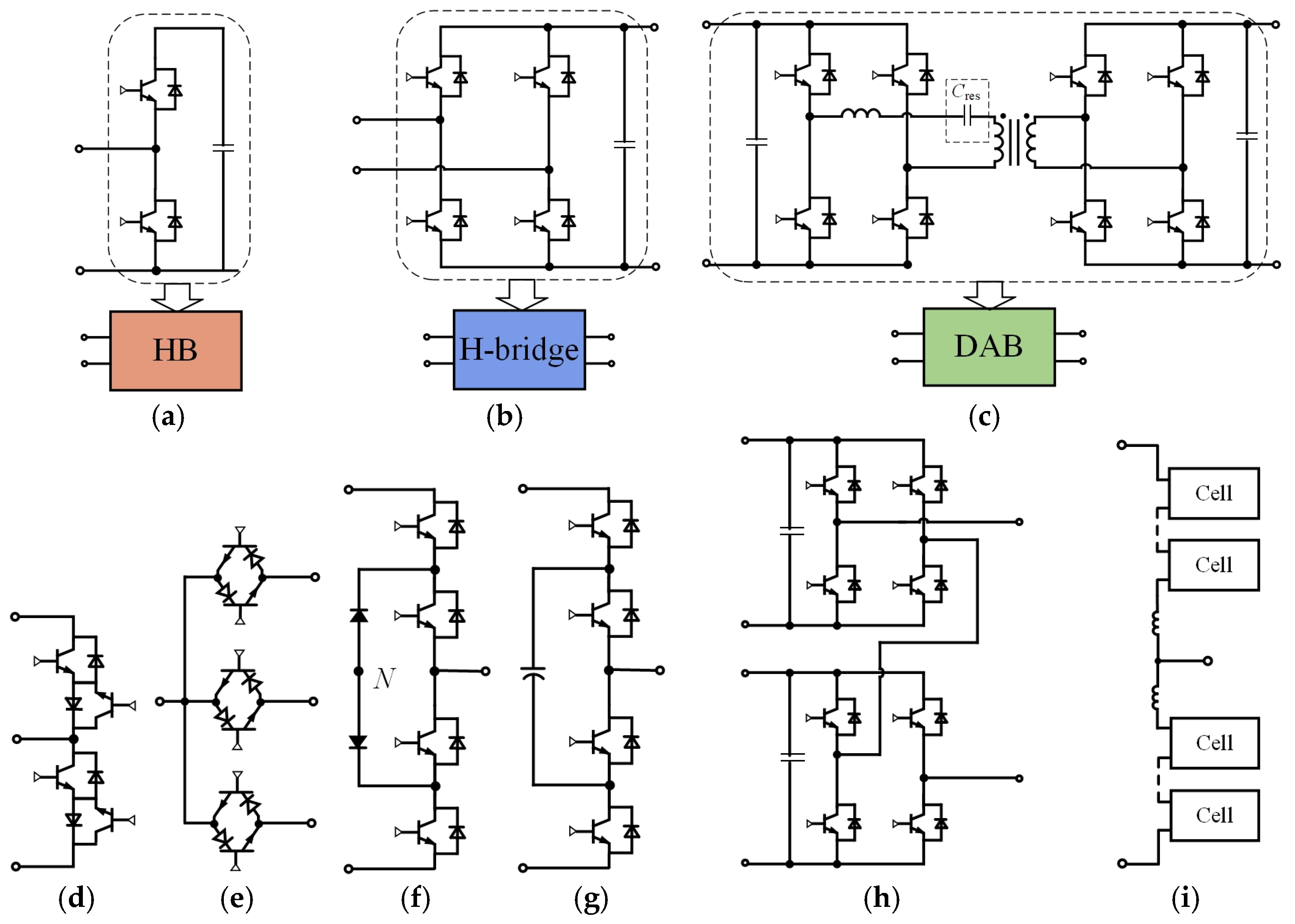
For connecting the MV and LV distribution networks with DER, it is most effective to use SST with the LV side PEC designed as a parallel-connected two-level converter and the MV side PEC having modular designs such as a cascade full-bridge PEC (H-bridge) and/or a modular multi-level converter (MMC). This allows for the required level of isolation on the MV side. Additionally, the modular PEC design enables the individual module backup and the generation of multi-level voltage, eliminating the need for passive filters. Thus, the topologies of PEC on the SST MV side can vary, as illustrated in Figure 2 [71].
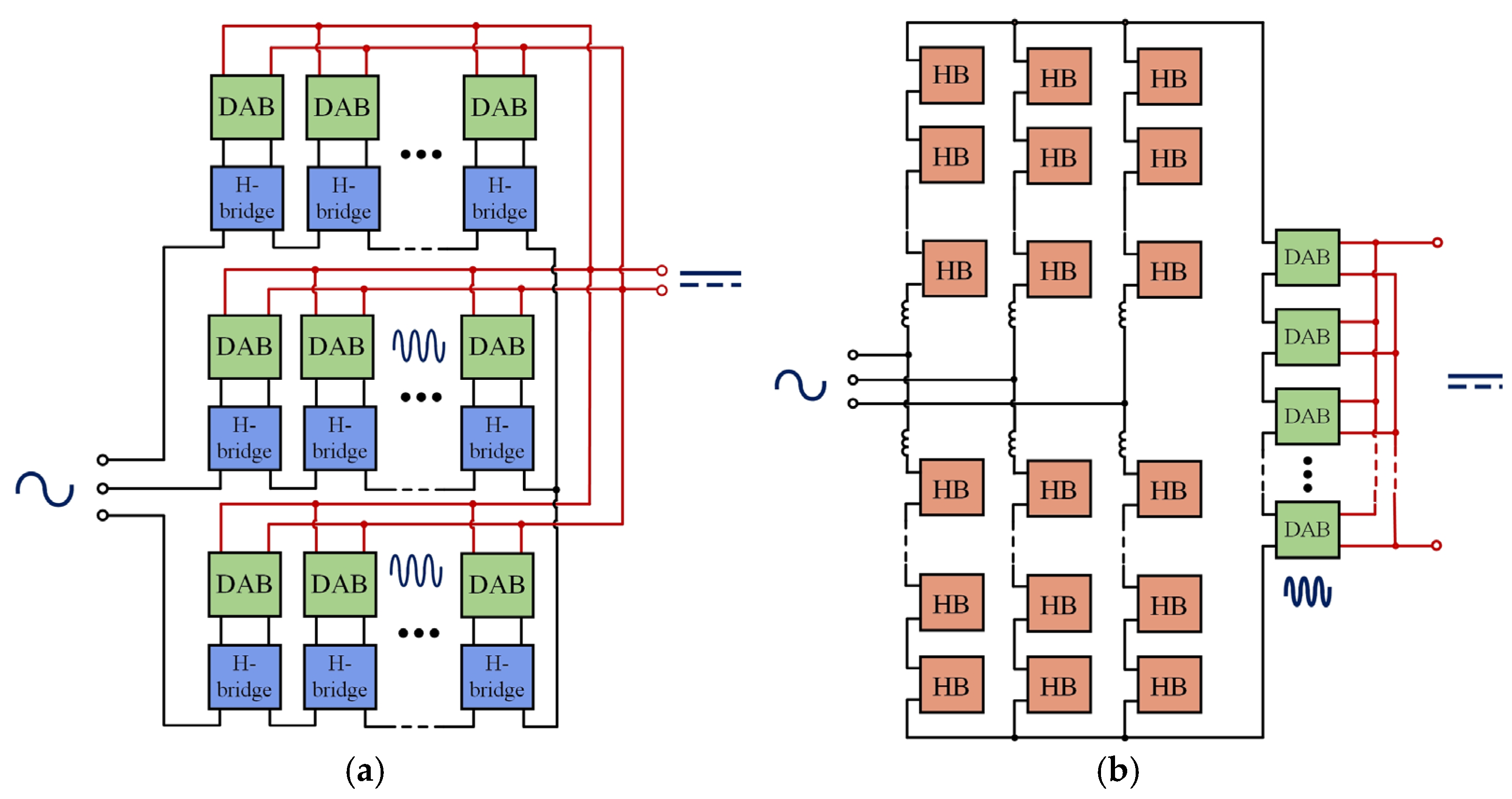
Figure 3a shows the SST topology, which uses three-phase H-bridges and dual active bridges (DABs) to supply/consume power through the galvanic isolation module. On the LV side of the galvanic isolation module, the DABs are connected in parallel to form an LV DC bus. In this case, the LV AC output circuit can be created by converting DC to AC. Figure 3b illustrates the SST topology, which employs MMC to transfer power from the MV AC network to the MV DC network. In this case, the LV DC network is created by a series-connected DAB at the input and a parallel-connected DAB at the output.
The main SST topologies (Figure 3) use a large number of DAB modules, which require a large number of medium- (0.5–5 kHz) or high- (5–20 kHz) frequency transformers (MHFTs) in the galvanic isolation module. This complicates power balancing between individual modules. In addition, implementing a DC MV network in SST requires a significant number of high-capacity capacitors, which hinders the creation of a stable MV DC bus in SST. The use of SST in MV distribution networks calls for an increase in the operating voltage of the PEC to tens of kilovolts. This can be achieved utilizing modern semiconductor switches based on silicon carbide polytypes (SiC). The operating voltage of the SST can be boosted using multi-level topologies. The PECs developed relying on such topologies combine various connection methods (series, parallel) of individual modules to obtain MMC [72,73]. The series-parallel connection of the DAB converters can be replaced by a bidirectional MMC (Figure 4). This engineering solution eliminates the need to use numerous high-capacity capacitors and employs only one high-frequency or medium-frequency transformer [74]. However, this requires several stages of current conversion, which necessitates a large number of active devices and leads to deterioration of specific indicators and an increase in the cost of SST.
Low-frequency current can be converted into medium/high-frequency current using direct matrix converters, for example, a single-stage modular multi-level matrix converter. It does not contain capacitors, which hinders the establishment of stable MV and LV DC buses. An alternative to direct matrix converters is indirect ones, which employ capacitors, but the number of active elements does not decrease, since half-bridges and more complex control algorithms are needed.
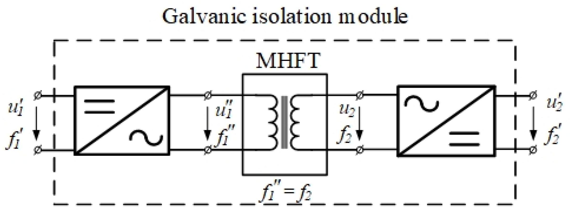
The use of half-bridges in PECs may be ineffective because of a capacitor discharge onto the load connected to the SST via an overhead power transmission line. The SST efficiency is enhanced using H-bridges with high-capacity capacitors instead of half-bridges. PECs based on half-bridges are utilized to connect the load via cable power lines that have their charging power, while PECs based on H-bridges are used to connect the load via overhead power lines. Optimization of the PEC and medium- or high-frequency transformer (MHFT) configuration within SST is aimed at deep integration of the MHFT elements into the PEC and vice versa. This allows switching from a two-stage to a single-stage conversion, eliminating the intermediate DC link and reducing the number of passive elements. This approach, however, leads to a more complex design of the SST and excludes the use of modular components [75]. The SST galvanic isolation module provides the formation of the DC output voltage. Its use for converting DC into DC based on the DAB converter is the most common solution, shown in Figure 5.
The cascaded connection of modules for direct integration of SST into the MV network requires several DABs, which increases the number of galvanic isolation modules. Although this allows for the SST modularity, the use of several galvanic isolation modules complicates the design of SST and creates additional difficulties.

4. SST Control Principles

The concept of current conversion by using multiple active bridges (MAMs) is widely applied in SST. It involves the use of several H-bridges integrated into one galvanic isolation module. This configuration reduces the weight and size of the galvanic isolation module through the use of one MHFT, while simultaneously boosting the transmitted power owing to the high variability of H-bridge configurations [76].
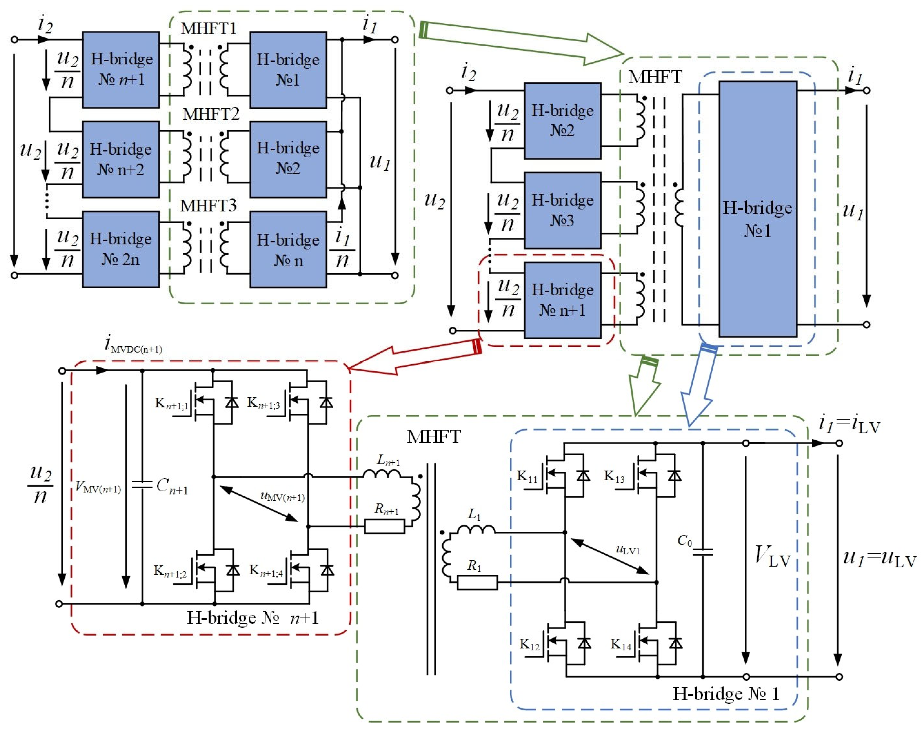
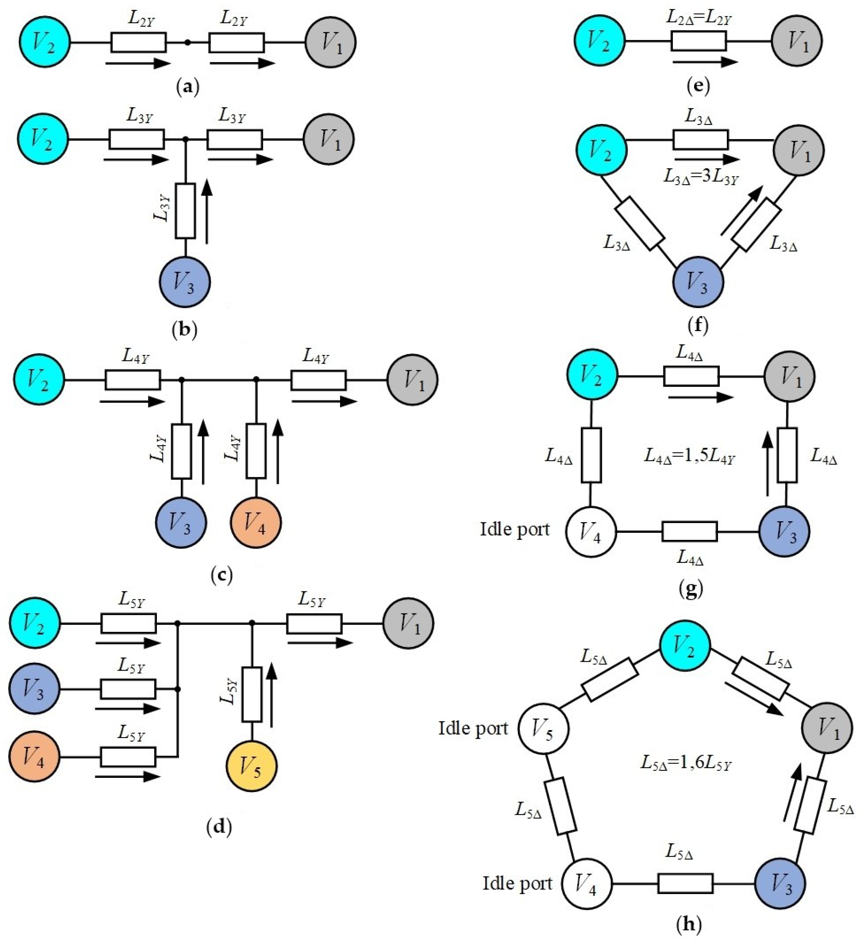
Figure 6 demonstrates an example of a flow diagram of a galvanic isolation module for one phase of an SST based on an MAB DC-DC PEC, as the most common PEC topology.
Power in the MAB converter is transmitted through star-connected multiple active H-bridges and/or delta-connected multiple active H-bridges on the MV side [77]. Electricity transmission from the MV network to the LV network can rely on a star-connected multiple active H-bridge, while electricity transmission only from adjacent H-bridges can be carried out using a delta-connected multiple active H-bridge, as shown in Figure 7.
Increasing the number of active bridges on the MV or LV side raises the percentage of transmitted power from 62% for DAB (achieving 81% for triple active bridge (TAB) and 93% for quad active bridge (QAB)) to 100% for penta active bridge (PAB).
When using DAB, the transmission of active power from the MV winding to the LV winding of the SST is ensured based on the pulse-width modulation (PWM) control method with a single-phase shift:
P DAB 12 = 1 4 V 1 V 2 f sw L 2 Y D 1     D ,
where V1 and V2 are effective values of input and output voltage of the DAB-based galvanic isolation module; D = ϕ/π is the PWM duty cycle, where ϕ is the phase shift; and fsw is the switching frequency.
However, for TAB, the value of active power transmitted from the MV network to the LV network is calculated using Formulas (2) and (3):
P TAB 12 = 1 6 V 1 V 2 f sw L 3 Y D 1 D ,
P TAB 13 = 1 6 V 1 V 3 f s w L 3 Y D 1 D ,
Given the conditionally positive direction in Figure 7d, the total active power supplied to the LV H-bridge is determined by summing up PTAB12 and PTAB13, which equals:
P TAB 1 = 1 6 V 1 ( V 2   +   V 3 ) f sw L 3 Y D 1     D ,
Similarly, the total power supplied to the SST LV network is determined for the QAB and PAB, using Formulas (5) and (6):
P QAB 1 = 3 16 V 1 ( V 2   +   V 3 ) f sw L 4 Y D 1     D ,
P PAB 1 = 1 5 V 1 ( V 2 +   V 3 ) f sw L 5 Y D 1 D
The dynamic control equations are discussed in detail in [78].
In addition to PWM with a single-phase shift, the DAB and MAB can be controlled by other types of PWM with an extended-phase shift and a dual-phase shift [79]. An extended-phase shift is used to reduce the reverse power flow that occurs with PWM operating with a single-phase shift. In the case of an extended-phase shift, the switches on the transmitting side are switched by an extended waveform.
The reactive power and the current flowing through the source are reduced through PWM control with a dual-phase shift. In a dual-phase shift control scheme, the phase is shifted on the primary and secondary sides of the SST galvanic isolation module. The phase shift between the branches of the MHFT primary winding is internal, while between the DABs, it is external. Thus, the primary and secondary voltages represent a quasi-meander, since both bridges operate with a phase shift. Operation of PWM with a dual-phase shift enables transmission of more power than with a single-phase shift and an extended-phase shift.
In addition to “hard” switching in DAB, “soft” switching of all switches can be implemented throughout the entire operating time, i.e., at zero voltage. To this end, a series resonant circuit is used. The series resonant circuit utilized in DAB or MAB increases the voltage conversion coefficient and the efficiency of PEC (up to 1%), minimizing the current load [80].
The results of the analysis of the main features of the PWM control methods of SSTs are summarized in Table 1 [78].
An analysis of Table 1 shows that the choice of a specific SST control method is based on a trade-off between complexity, cost, and efficiency. For simple and reliable solutions, single-phase-shift PWM is preferred. Despite its complexity, dual-phase-shift PWM is used to improve the efficiency and specific performance of the SST. Sinusoidal PWM is the standard for achieving a pure low-frequency sine wave at the SST output, but not for its high-frequency section, which is controlled using phase-shift keying (PSK), which generates a stable high-frequency signal in the galvanic isolation module.
Depending on the topology and purpose of the SST, different control objectives can be set alongside different initial data and parameters that need to be controlled. SSTs are widely used in distribution networks with DER for connecting MV and LV networks of both AC and DC. Coordination of SST control in the event of islanding is not required, since the system will behave like a normal distribution network with AC and DC microgrids [81].
At their core, SSTs implement a direct DC interface, facilitating the efficient integration and operation of DERs in distribution networks. Therefore, SSTs are widely used in distribution networks to connect electric charging stations. When using SSTs in distribution networks with DERs, increased requirements are placed on SSTs for network stability, power regulation quality, and power quality. This allows for additional benefits in the form of high SST efficiency and the ability to control power flows [82]. When using SSTs to connect electric vehicle charging infrastructure, SSTs are required to quickly deliver active power (fast charging), stabilize DC bus voltage, and ensure bidirectional power flow [83], which is possible through the use of DAMs that form a stable DC bus [84].
In this case, the SST parameters to be controlled encompass the following: LV active/reactive power—PLV/QLV; voltage of LV AC/DC—uLV/VLV; LV AC—iLV; MV active/reactive power—PMV/QMV; MV AC—iMV; DC voltage of the galvanic isolation module on the MV side—VMV; DC current of the galvanic isolation module on the MV side—iMV [85].
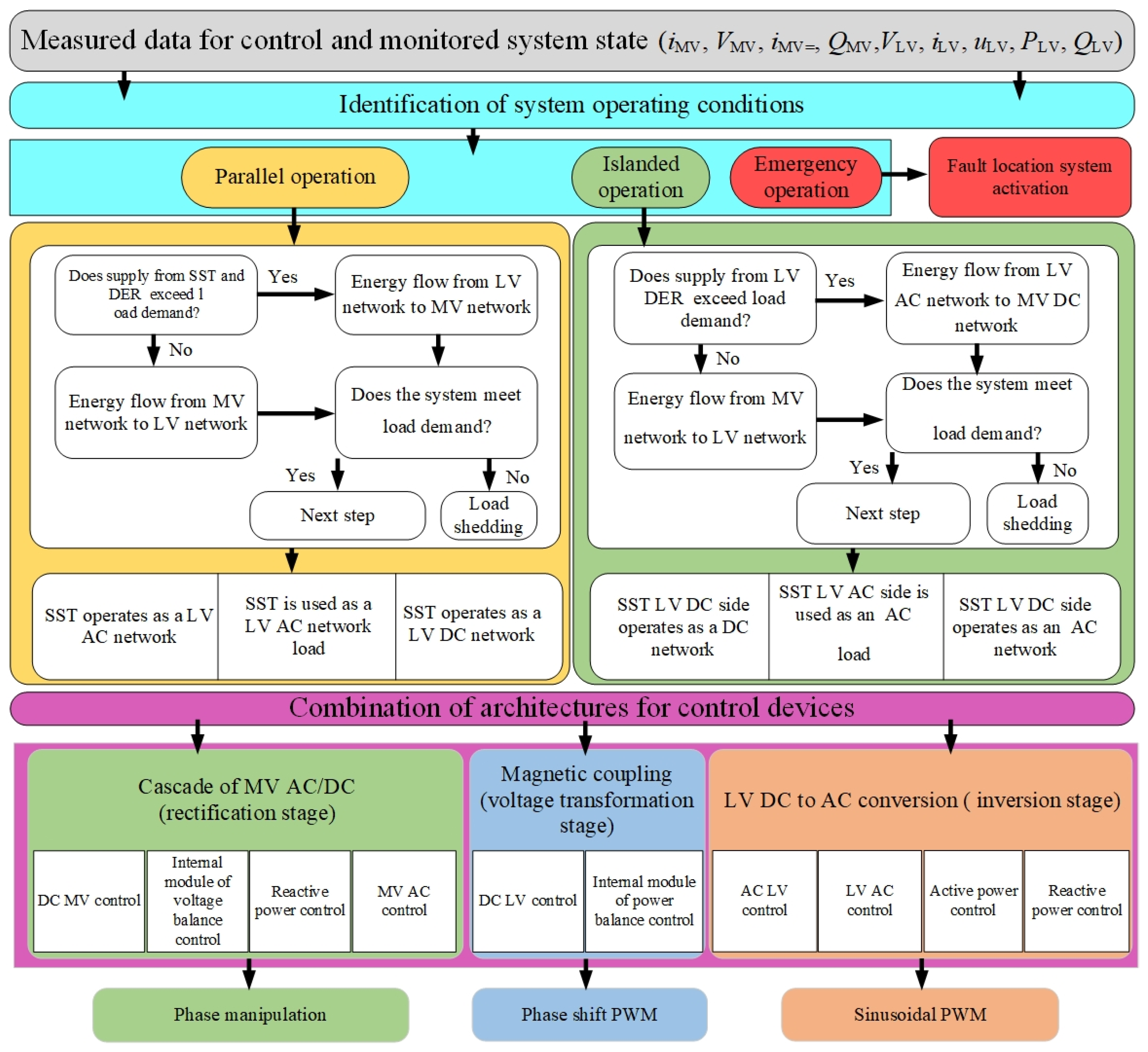
Figure 8 shows the coordinated architecture of the control system for the distribution network with SST.
Figure 8 shows the architecture of a coordinated SST controller, consisting of four control levels. The first level collects data from the distribution network and generates reference control signals, which determine the SST operating mode: network mode, island mode, or emergency mode. Upon identifying a fault, the controller automatically activates the SST’s built-in fault localization system. In the event of a non-critical fault, the SST can continue to operate in network mode; otherwise, the SST will operate only in island mode. The second control level determines the power flow direction and the SST control method depending on the load magnitude. The third control level is the primary one, as it makes decisions about the use of a combination of SST controllers. The fourth level generates control signals in accordance with the decisions made at the previous three levels.
The development of control systems for distribution networks with SST relies on vector control methods based on a synchronously rotating dq-coordinate system. By regulating the voltage in the low-frequency (for example, u1 and u2) and medium-frequency (for example, uMV(n+1) and uLV1) loops of the SST, it is possible to control the power transmitted between the MV and LV sides. Therefore, organizing the SST control involves considering processes in the low-frequency and medium-frequency loops to maintain the power balance [86].
Consequently, the SST is controlled at three levels:
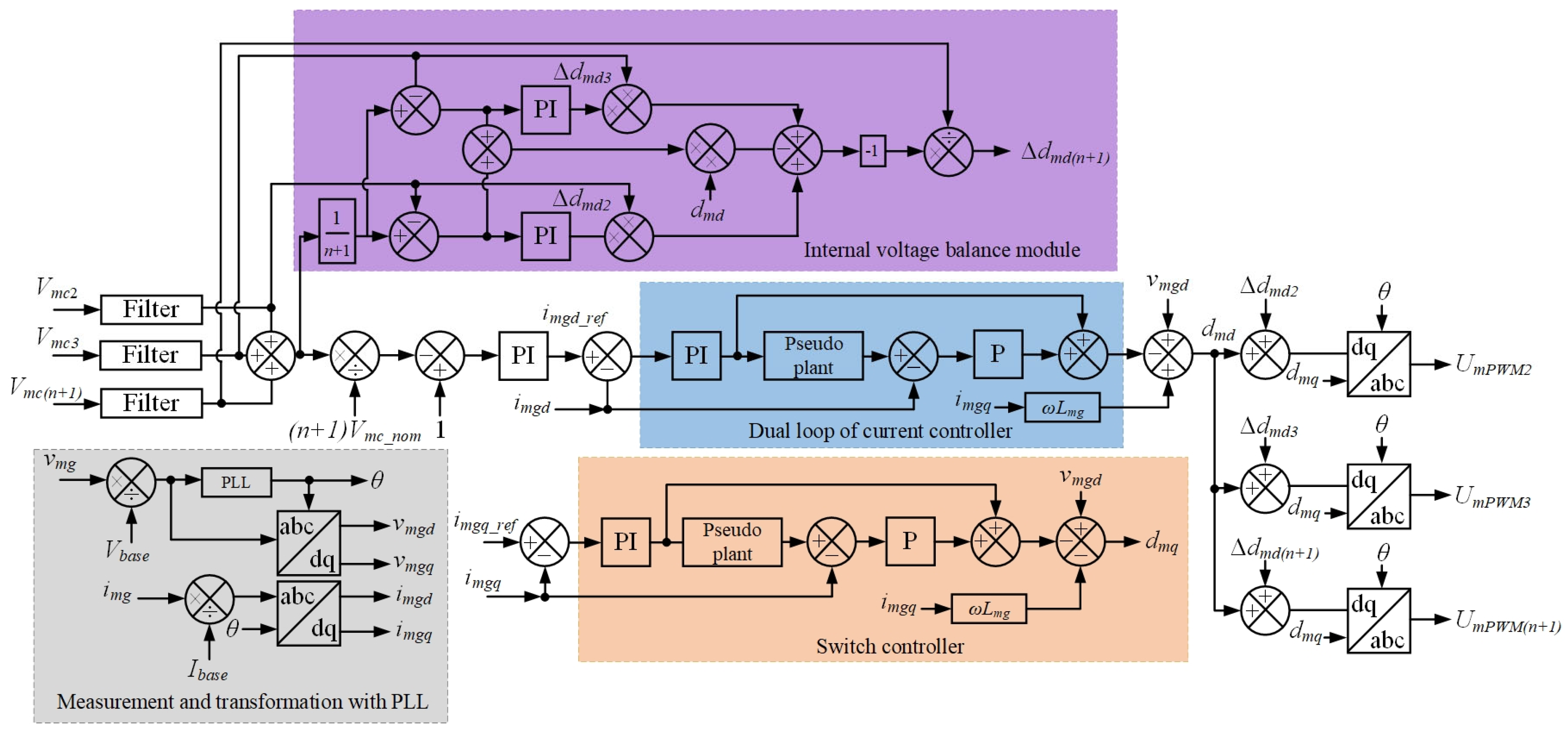
  • the input module controller, which is responsible for the control of cascaded PECs with a dual-loop current control and the internal power balance module regulator during rectification (Figure 9);
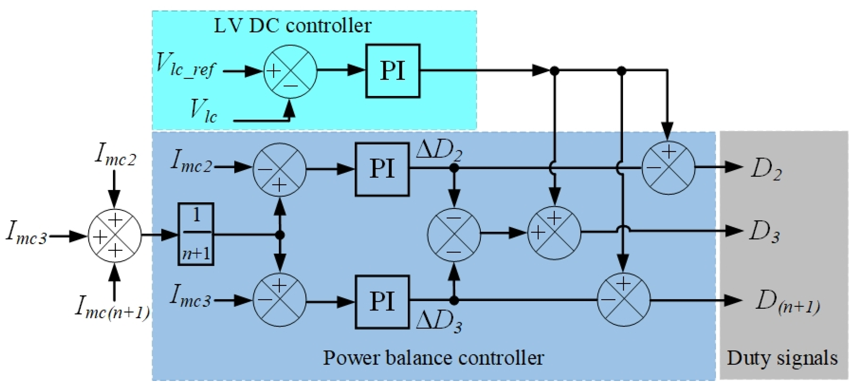
  • the galvanic isolation module controller, which controls electric power conversion, through the use of MHFT and PEC for DC-to-DC conversion (Figure 10);
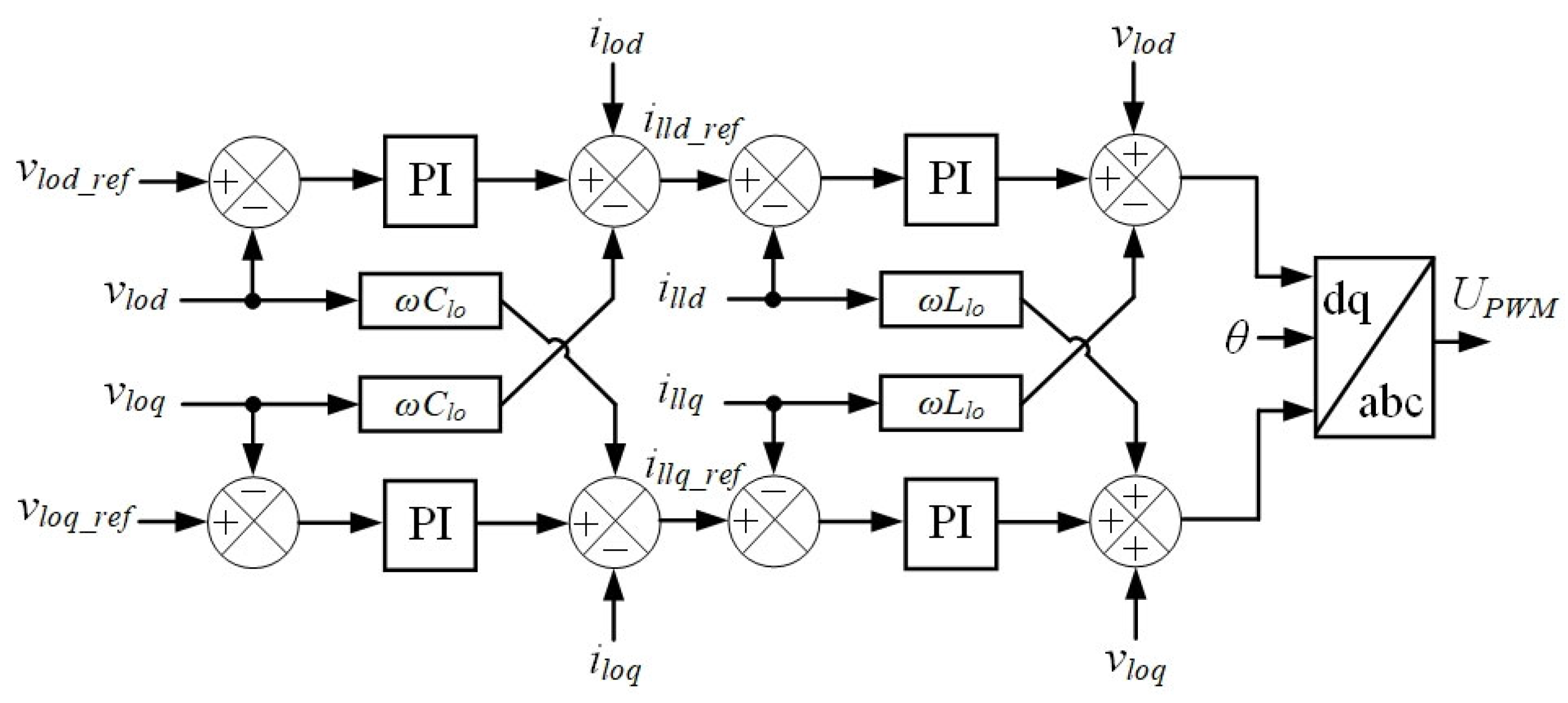
  • the output module controller, which controls cascaded PECs for converting low-voltage DC into low-voltage AC (Figure 11).
Figure 9 shows the architecture of a cascade rectifier with a dual-loop current regulator and a voltage balance regulator. Using a dual-loop current regulator instead of a PI controller minimizes higher harmonic components, while the additional use of a voltage balance regulator eliminates voltage imbalances between SST cells [87]. Using this architecture of a cascade rectifier controller allows for high current loop bandwidth (approximately 160 Hz), ensuring high dynamic performance and SST control quality.
Figure 10 shows the architecture of the SST galvanic isolation module’s DC/DC converter, in which the power regulator simultaneously balances the voltage (with a gain of 0.0001) to maintain (with an integral gain of 0.002) a specified voltage level on the LV side of the SST. A current regulator with a proportional gain ensures a uniform current on the MV side of the SST. The use of a narrow bandwidth allows for the use of high frequencies for power transmission from MV to LV distribution networks and vice versa, reducing the weight and size of the SST.
Figure 11 shows the controller for a low-voltage DC-AC converter. The LV SST output must operate both in power distribution mode in the MV distribution networks and in load supply mode on the LV side. In load supply mode, the LV inverter must provide both active and reactive power. This controller is similar to a dual-loop current controller (Figure 9), but without a voltage balance controller between modules, as the current drive components are generated by the active and reactive power controller, not the voltage regulator. This controller architecture allows for the use of a high bandwidth (198 Hz) and contributes to a significant reduction in the magnitude of higher harmonic current components.
Various architectures of the SST control system allow solving specific SST control problems. An architecture of the SST control system with switching at a frequency of 50 Hz is proposed in [88]. It consists of five control stages:
  • maintaining the voltage VLV at a given reference value on the LV side of the SST;
  • balancing the cells for regulating the voltage on the DC bus of cascaded H-bridges, which allows the cells of the H-bridge to switch at the grid frequency without any additional voltage balance control;
  • switching the cells of the cascaded H-bridges at the grid frequency with such switching angles of the H-bridge cells that the AC voltage inversion stages correspond to the input voltage of the SST (u1 or u2), and that the voltage conversion errors are minimal;
  • switching in the galvanic isolation module at a high-frequency (40 kHz) to eliminate instantaneous voltage conversion errors introduced by the H-bridge cells and to yield a sinusoidal voltage waveform with a higher switching frequency on the SST MV side;
  • using recirculating logic to minimize the unevenness of voltage and power distribution between the cells of the cascaded H-bridges to minimize losses in semiconductors arising due to switching on the SST MV side at a frequency of 50 Hz. In this case, switching at high frequencies is carried out only in the galvanic isolation module of the SST to increase its efficiency.
The use of the considered SST architecture allows the use of traditional silicon (Si)-based insulated gate bipolar transistors (IGBTs) instead of expensive silicon carbide (SiC)-based metal-oxide-semiconductor field-effect transistors (MOSFETs) [89,90]. This lowers the cost of the SST PEC by 46%, while providing almost the same efficiency as that achieved by relying on SiC-based MOSFETs (the PEC efficiency is 95.4%) [91]. Depending on the purpose of the SST and the architecture of its control system, the principles, algorithms, and stages of control may differ from those discussed above.

5. SST Control Methods

Normally, the SST control system employs traditional proportional (P), proportional-integral (PI), and proportional-resonance (PR) methods [92,93,94]. These methods are implemented by three blocks. Their independent control affects the stability and dynamic response parameters of the entire SST [95]. Traditional voltage control methods have disadvantages, such as integral saturation and tuning difficulties. As a result, the speed of the SST’s dynamic response to load fluctuations and voltage changes on the DC bus declines, reaction slows down, and power pulsations increase. Highly demanded control strategies based on the concept of coordinated SST control are explored in [96]. The study [97] proposes a method for SST power control that addresses the interaction between the rectifier block and the DC block to enhance controllability and stability. An SST control system proposed in [98] is based on the concept of compound control, integrating feedforward and feedback control strategies. Its application improves the dynamic characteristics of voltage changes on the MV and LV DC buses and enhances the performance of the SST.
In hybrid AC-DC networks, the SST PECs, which convert the direct current of DABs, operate under stochastic load fluctuations in the DC network. Therefore, it is important to have a fast dynamic response of the SST to these changes [99]. One of the solutions is the application of predictive voltage control for MAB to improve the dynamic characteristics and power balance [100].
The Finite Control Set Model Predictive Control (FCS-MPC) method operates by enumerating all possible voltage vectors, performing a one-to-two-step-ahead prediction, and calculating a cost function, a process requiring 50–200 Million Instructions Per Second (MIPS) [101]. While this method benefits from straightforward implementation and an inherent limitation on switching frequency, it is accompanied by significant drawbacks, including high current ripple, a variable switching frequency, and increasing complexity with a higher number of converter levels [102]. In contrast, the Triple-Vector MPC method solves two to three optimization problems to calculate required time intervals, demanding a higher computational performance of 200–500 MIPS [103]. This approach enables a reduction in current ripple and maintains a constant switching frequency, thereby improving output voltage and current quality. However, these advantages come at the cost of a more complex implementation, significantly higher computational demands, and a reliance on an accurate system model [104]. Thus, the FCS-MPC method is used when it is necessary to reduce costs and quickly develop a CS with a small number of states. When high power quality (low ripple; low non-sinusoidality) is required, the Triple-Vector MPC method should be used.
In [105], consideration is given to coordinated modeling of a small-signal DAB model based on the method of fast control, relying on an adaptive PI controller. However, the application of this method has significant difficulties.
In [106], a virtual power control method is proposed to derive the control variable from the DAB power model. This scheme does not require a current sensor on the inductor for power control, providing a fast dynamic response with a simple implementation. In [107], various predictive control methods used in the SST control module are presented.
Most of the known SST control methods employ individual control for each level of PEC to achieve the set goals. With this approach to control, the DC bus voltage changes in transient processes in the external network and in the internal processes within the SST. This affects the dynamic characteristics and stability of the entire SST control system.
Integrated control of all SST blocks is an effective way to improve its dynamic characteristics. Existing integrated SST control methods are based on traditional voltage control methods [108]. Further enhancement of the dynamic characteristics of the SST control systems necessitates the use of predictive control methods. Predictive control methods are characterized by simple consideration of nonlinearities and limitations, alongside fast response achieved through the principle of maintaining power balance [109]. They can also be implemented relying on the finite set method, which factors in the finiteness of the input values of control signals generated by semiconductor switches and on the three-vector predictive control model.
The finite set method transforms the control problem into an optimization problem. This method suggests selecting the optimal voltage vector by minimizing the cost function. Since the number of selected voltage vectors is limited to eight, the direction and amplitude of the voltage vectors are fixed. The use of this method causes significant current pulsations and a variable switching frequency, which complicates the design of filters and worsens the performance of the SST control system [110]. Furthermore, a high sampling frequency is essential to ensure the required control quality.
The application of a three-vector predictive control model of the SST is described in [98]. Its implementation relies on the use of power on the LV side of the network and voltage at the SST output, as well as a predictive model for PEC control on the MV and LV sides. In this case, two active vectors are found, and their execution time is calculated. After that, two active vectors and a zero vector are synthesized to implement the PEC switching. Thus, the three-vector model uses three vectors in one control cycle and factors in a combination of different switching states of the PEC. Compared with the finite set method, the three-vector model is more effective in suppressing harmonic components and interference. It reduces the switching frequency and maintains its fixed value.
The approaches considered the complexity of the SST control system, selected control parameters, and enhanced the dynamic characteristics of the DC link [111]. A direct power line, when used to combine the rectifier and the MAB block, enables a more effective power control of the SST, improving its dynamic response. The use of the direct predictive control method with a dual-phase shift facilitates a more precise phase shift angle selection, leading to improved power balance and faster speed of response when controlling the SST output voltage.
A strategy for predictive direct control of the SST power presented in [112] relies on the static nature of the ESS with a P–V2 characteristic, as well as on the predictive control of the DAB and the rectifier power. Figure 12 illustrates an example of this strategy’s implementation.
The presented model predictive control of SST, in comparison with traditional PI regulation, allows for an effective suppression of voltage fluctuations on the LV DC bus and contributes to the improvement in the dynamic characteristics of SST. It is important to note that the SST control system should be integrated into the control system of the distribution network with DER to gain maximum technical and economic effects from the use of SST.

6. Discussion

SSTs are not a single technology for DER integration but rather represent an evolution of the distribution network development with DERs. The reasons for this include limitations in the transmission of reverse power flows through older-generation power transformers; high energy losses when using full-scale power converters used in hybrid power transformers; the impossibility of integrating RES into distribution networks without the use of PECs; the efficiency of using DC distribution networks; and the possibility of using various approaches to managing distribution networks with DERs through the use of communication channels, as well as various types of local DER controllers in the form of DC/DC PECs.
The development of hybrid MV and LV distribution networks with DER is a promising strand for their evolution in the short and medium term. This stems from the large-scale introduction of various DER, including those relying on renewable energy sources, by industrial, commercial, and residential consumers. The widespread use of photovoltaic systems requires the creation of LV DC distribution networks [113]. In the context of the mass integration of DER into existing distribution networks, it is essential to improve the controllability of power flows [114]. This can be achieved through the reconstruction of passive distribution networks with a change in their configuration and the use of modern SSTs of various topologies.
This article examines the basic designs of SSTs based on H-bridges, DABs, and HBs. The choice of which depends on the method of power transmission via overhead or cable power lines. Using half-bridges in SSTs can be inefficient due to the discharge of capacitors onto the load connected via overhead power lines. To improve efficiency, H-bridges with large capacitors are used instead of half-bridges in SSTs. Half-bridge-based SSTs are used to connect loads via cable power lines with their own charging capacity, while H-bridge-based SSTs are used to connect loads via overhead power lines. When using SSTs to connect electric charging stations, DABs are preferred.
This review highlights the impact of the number of converter levels on the energy density transmitted through SSTs. When using DAB, the maximum power does not exceed 62%, while using PAB, it is possible to achieve 100% conversion of the energy supplied to the SST input.
PEC SSTs have a variety of topologies. Systematizing the key elements of H-bridge, DAB, and HB and determining the feasibility of their use depending on the characteristics of distribution networks and the SST purpose will allow further research to focus on the technical and economic impact of their application. The PAB-based SST topology can be used as the basic SST topology. This review does not consider direct matrix SST topologies, as they cannot be used to create DC distribution networks, and indirect matrix converters have fewer control capabilities, although they can create DC buses.
The use of active bridges simplifies the design of SST modules. Each SST module has its own optimal PWM implementation methods, discussed in this review, which improve the efficiency of the TTT.
The predictive control methods used in SSTs can be implemented using either FCS-MPC or Triple-Vector MPC, which solve different problems. FCS-MPC is the simplest SST control method, requiring no additional optimization depending on the specifics of distribution networks. However, its use does not improve power quality, which is achieved with Triple-Vector MPC due to precise optimization and a significantly higher computational load.
The review demonstrates that SSTs have different topologies. The choice of SST topology depends on its intended application, while the intended application determines the goals of control. Various initial data can be used to control SSTs, allowing for the selection of parameters that need to be controlled in accordance with the pace of the process [115].
The use of SSTs in hybrid MV and LV distribution networks allows addressing a large number of urgent problems in the power flow control for both AC and DC networks. SSTs contribute to compensation for voltage dips, fluctuations, and interruptions; regulation of voltage, current, frequency, and power factor in low-voltage networks, while also reducing the level of harmonic components in both currents and voltages.
Currently, SSTs cannot become a full-fledged replacement for power transformers, which are widely used in passive MV AC distribution networks, since their capital cost and energy loss indicators are worse. The use of SSTs, however, is fully justified when it is necessary to establish a low-voltage DC network to integrate DER and organize interaction with DC microgrids. SSTs are cost-effective for a hybrid distribution network (50% DC and 50% AC). The presence of a DC link in the SST enables a relatively simple integration of DER that generates DC power, without intermediate conversion to AC [116].
The use of PEC in SSTs solely to convert AC into AC significantly reduces their cost-effectiveness, which is associated with the significant cost of high-voltage power semiconductor switches for high currents. Choosing a specific flow diagram for PEC on the MV side and on the LV side should be guided by the intended PEC application and should take place during the design stage.
At present, SSTs are not widely used in existing MV distribution networks. However, SSTs have been in trial operation in some countries for over 10 years. Their serial production will enable manufacturers to optimize their topologies and cost indicators.
A wider implementation of SST in hybrid MV and LV distribution networks with DER requires collecting and summarizing the experience of operating SSTs of various topologies, considering their specific features and operating conditions. In addition, it is crucial to summarize the experience of using SST control systems and integrating them into control systems of hybrid distribution networks with DER. This will allow power grid companies to plan the use of SSTs in implementing the projects for new hybrid distribution networks and in upgrading the existing MV and LV distribution networks. The introduction of SSTs should aim to improve the quality of electricity and boost the reliability of power supply to consumers in various topological and operational scenarios.
Complex projects that involve the introduction of SSTs, SST control systems, and control systems of hybrid distribution networks with DER will offer practical experience in their application, evaluate their actual technical and economic effects, and inform decisions on replication of these technologies.

Prospective Areas for Research and Development

The development of SSTs together with their control systems is essential to address specific pressing issues while minimizing both capital and operating costs. This concept stems from the understanding that not every project requires the full capabilities of SST or its control system. A serially manufactured line of SSTs with integrated control systems will make it easier for design organizations to select them for the required functionality.
It is crucial to develop methodological recommendations for the design of new distribution networks with DER using SST and reconstruction of existing ones. This is important for design institutions that perform these types of work. Methodological recommendations should contain information on both the selection of SSTs with integrated control systems and the integration of SST control systems into the control systems of MV distribution networks.
Utilizing SSTs is most promising for islanded operation of microgrids with DER under emergency scenarios in MV AC distribution networks. It is necessary to develop standard technical solutions for the power supply to cottage villages with various numbers of households and levels of power consumption.
The integration of SSTs in distribution networks with DER introduces challenges in the organization of protection, since the fault feeding currents from SSTs slightly exceed the nominal values. The protection of LV distribution networks with DER, which are fed through SST, is not presented in this review.

7. Conclusions

This review contains the results of a comprehensive analysis of the design features of CSs and SSTs for use in hybrid distribution networks with DERs. The presented results enable design staff to select the most effective principles and control methods for SSTs of various designs to accelerate CS development and implementation.
When establishing hybrid MV and LV distribution networks, it is effective to use solid-state transformers, given their complete controllability due to power electronic converters. An analysis of international experience reveals that SSTs are widely used in distribution networks with diverse distributed energy resources for connecting MV and LV networks of both alternating and direct current.
The review presents the main SST topologies, detailing the principles of SST construction and the control strategies implemented for SST. It also highlights the development of STT control systems using a configuration of active bridges, simplified to dual active bridges within power electronic converters.
The development of SST control systems for different SST topologies will facilitate solving the required set of problems while eliminating redundant solutions that lead to a significant increase in their cost. The advancement of the SST control systems, coupled with their integration into the control systems of hybrid distribution networks with DER, will significantly enhance the controllability of the MV and LV distribution networks. This is particularly crucial in the context of large-scale integration of diverse DER into LV networks of both alternating and direct current.

Author Contributions

Conceptualization, P.I. and V.V.; methodology, P.I. and K.S.; software, V.V.; validation, K.S.; formal analysis, P.I.; investigation, P.I., V.V. and K.S.; resources, V.V.; data curation, P.I.; writing—original draft preparation, P.I. and V.V.; writing—review and editing, P.I., V.V. and K.S.; visualization, V.V.; supervision, P.I.; project administration, K.S.; funding acquisition, P.I. and K.S. All authors have read and agreed to the published version of the manuscript.

Funding

The research was carried out at ERI RAS at the expense of a grant from the Russian Science Foundation No. 21-79-30013-P, https://rscf.ru/project/21-79-30013/, accessed on 10 October 2025.

Data Availability Statement

The original contributions presented in the study are included in the article. Further inquiries can be directed to the corresponding author.

Conflicts of Interest

The authors declare no conflict of interest. The funders had no role in the design of the study; in the collection, analyses, or interpretation of data; in the writing of the manuscript; or in the decision to publish the results.

References

  1. Di Silvestre, M.L.; Favuzza, S.; Sanseverino, E.R.; Zizzo, G. How Decarbonization, Digitalization, and Decentralization are changing key power infrastructures. Renew. Sustain. Energy Rev. 2018, 93, 483–498. [Google Scholar] [CrossRef]
  2. Muhanji, S.O.; Schoonenberg, W.C.H.; Farid, A.M. Transforming the Grid’s Architecture: Enterprise Control, the Energy In-ternet of Things, and Heterofunctional Graph Theory. IEEE Power Energy Mag. 2019, 17, 71–81. [Google Scholar] [CrossRef]
  3. Voropai, N. Electric Power System Transformations: A Review of Main Prospects and Challenges. Energies 2020, 13, 5639. [Google Scholar] [CrossRef]
  4. Florkowski, M.; Hayashi, H.; Matsuda, S.; Moribe, H.; Moriwaki, N.; Jones, D.; Pauska, J. Digitally Boosted Resilience: Digitalization to Enhance Resilience of Electric Power System. IEEE Power Energy Mag. 2024, 22, 100–109. [Google Scholar] [CrossRef]
  5. Boyko, E.; Byk, F.; Ilyushin, P.; Myshkina, L.; Suslov, K. Methods to Improve Reliability and Operational Flexibility by Inte-grating Hybrid Community Mini-Grids into Power Systems. Energy Rep. 2023, 9, 481–494. [Google Scholar] [CrossRef]
  6. Sidorov, D.; Panasetsky, D.; Tomin, N.; Karamov, D.; Zhukov, A.; Muftahov, I.; Dreglea, A.; Liu, F.; Li, Y. Toward Zero-Emission Hybrid AC/DC Power Systems with Renewable Energy Sources and Storages: A Case Study from Lake Baikal Region. Energies 2020, 13, 1226. [Google Scholar] [CrossRef]
  7. Burger, S.P.; Jenkins, J.D.; Huntington, C.S.; Pérez-Arriaga, I.J. Why Distributed?: A Critical Review of the Tradeoffs Between Centralized and Decentralized Resources. IEEE Power Energy Mag. 2019, 17, 16–24. [Google Scholar] [CrossRef]
  8. Ilyushin, P.; Filippov, S.; Kulikov, A.; Suslov, K.; Karamov, D. Intelligent Control of the Energy Storage System for Reliable Operation of Gas-Fired Reciprocating Engine Plants in Systems of Power Supply to Industrial Facilities. Energies 2022, 15, 6333. [Google Scholar] [CrossRef]
  9. Altamirano Flores, E.; Tinco Curi, V.; Tamayo Mattos, S.M.; Cáceres Cayllahua, E.; Quiroz Quezada, P.R. La Generación Distribuida como Complemento para la Confiabilidad del Suministro Eléctrico: Para el Desarrollo Económico Social Peruano. Cent. Sur 2025, 9, 15–26. [Google Scholar] [CrossRef]
  10. Ilyushin, P.V.; Filippov, S.P. Under-frequency load shedding strategies for power districts with distributed generation. In Proceedings of the 2019 International Conference on Industrial Engineering, Applications and Manufacturing (ICIEAM), Sochi, Russia, 25–29 March 2019. [Google Scholar] [CrossRef]
  11. Čaušević, S.; Warnier, M.; Brazier, F.M. Self-determined distribution of local energy resources for ensuring power supply during outages. Energy Inform. 2019, 2, 6. [Google Scholar] [CrossRef]
  12. Blasi, T.M.; de Aquino, C.C.C.B.; Pinto, R.S.; de Lara Filho, M.O.; Fernandes, T.S.P.; Vila, C.U.; Aoki, A.R.; dos Santos, R.B.; Tabarro, F.H. Active Distribution Networks with Microgrid and Distributed Energy Resources Optimization Using Hierar-chical Model. Energies 2022, 15, 3992. [Google Scholar] [CrossRef]
  13. Jia, Q.; Jiao, W.; Chen, S.; Yan, Z.; Sun, H. A Trustworthy Cloud-Edge Collaboration Framework for Scheduling Distributed Energy Resources in Distribution Networks. IEEE Trans. Smart Grid 2025, 16, 2691–2694. [Google Scholar] [CrossRef]
  14. Zapparoli, L.; Oneto, A.; Parajeles Herrera, M.; Gjorgiev, B.; Hug, G.; Sansavini, G. Future Deployment and Flexibility of Distributed Energy Resources in the Distribution Grids of Switzerland. Sci. Data 2015, 12, 1491. [Google Scholar] [CrossRef]
  15. Guo, Y.; Wang, S.; Chen, D. A Time- and Space-Integrated Expansion Planning Method for AC/DC Hybrid Distribution Networks. Sensors 2025, 25, 2276. [Google Scholar] [CrossRef]
  16. Cai, Y.; He, H.; Wen, Y.; Gao, Y.; Zhang, Q.; Zhang, S.; Lin, G. Optimal Scheduling Method of Medium and Low Voltage AC-DC Hybrid Distribution Network Based on Edge Cloud Cooperation. Recent Adv. Electr. Electron. Eng. 2025, 18, e23520965339482. [Google Scholar] [CrossRef]
  17. Mehdi, A.; Hassan, S.J.U.; Haider, Z.; Kim, H.-Y.; Hussain, A. Communication-Less Data-Driven Coordination Technique for Hybrid AC/DC Transmission Networks. Energies 2025, 18, 1416. [Google Scholar] [CrossRef]
  18. Mokgonyana, L.; Smith, K.; Galloway, S. Reconfigurable Low Voltage Direct Current Charging Networks for Plug-In Electric Vehicles. IEEE Trans. Smart Grid 2019, 10, 5458–5467. [Google Scholar] [CrossRef]
  19. Deng, M.; Zhao, J.; Huang, W.; Wang, B.; Liu, X.; Ou, Z. Optimal Layout Planning of Electric Vehicle Charging Stations Con-sidering Road–Electricity Coupling Effects. Electronics 2025, 14, 135. [Google Scholar] [CrossRef]
  20. Zhang, X.; Liu, J. Distributed Power, Energy Storage Planning, and Power Tracking Studies for Distribution Networks. Electronics 2025, 14, 2833. [Google Scholar] [CrossRef]
  21. Volnyi, V.; Ilyushin, P.; Suslov, K.; Filippov, S. Approaches to Building AC and AC–DC Microgrids on Top of Existing Passive Distribution Networks. Energies 2023, 16, 5799. [Google Scholar] [CrossRef]
  22. Garcia, I.; Santana, R. Unified Framework for the Analysis of the Effect of Control Strategies on On-Load Tap-Changer’s Automatic Voltage Controller. IEEE Trans. Autom. Sci. Eng. 2024, 21, 1539–1548. [Google Scholar] [CrossRef]
  23. McGrath, A. Advances in MV voltage regulators. In Proceedings of the 2013 48th International Universities’ Power Engineering Conference (UPEC), Dublin, Ireland, 2–5 September 2013; pp. 1–4. [Google Scholar] [CrossRef]
  24. Astashev, M.G.; Lunin, K.A.; Panfilov, D.I.; Petrov, M.I.; Rashitov, P.A. Semiconductor Voltage Regulators-Stabilizers for Distribution Networks. Power Technol. Eng. 2021, 55, 310–313. [Google Scholar] [CrossRef]
  25. Mishra, M.K. Power Electronics in Energy Systems: Enhancing Efficiency and Quality in Electrical Energy Conversion and Distribution. J. Data Sci. Inf. Technol. 2024, 1, 24–31. [Google Scholar] [CrossRef]
  26. Jarret, K.; Hedgecock, J.; Gregory, R.; Warham, T. Technical Guide to the Connexion of Generation to the Distribution Network; Department of Trade and Industry: London, UK, 2004. [Google Scholar]
  27. Schneider, L.; Pehnt, M. Embedding Micro Cogeneration in the Energy Supply System. In Micro Cogeneration; Springer: Berlin/Heidelberg, Germany, 2006. [Google Scholar] [CrossRef]
  28. Buchholz, B.M.; Styczynski, Z. Smart Grids—Fundamentals and Technologies in Electricity Networks; Springer: Berlin/Heidelberg, Germany; New York, NY, USA; Dordrecht, The Netherlands; London, UK, 2014; 396p. [Google Scholar]
  29. Electricity NIC Submission: SP Energy Networks—LV Engine, Nov 2017. Available online: https://www.ofgem.gov.uk/publications/electricity-nic-submission-sp-energy-networks-lv-engine (accessed on 26 August 2025).
  30. Syed, I.; Khadkikar, V.; Zeineldin, H.H. Loss Reduction in Radial Distribution Networks Using a Solid-State Transformer. IEEE Trans. Ind. Appl. 2018, 54, 5474–5482. [Google Scholar] [CrossRef]
  31. Kala, H.; Rawat, M.S.; Uniyal, A. Optimal allocation and technoeconomic analysis of solid state transformer in distribution network. Comput. Electr. Eng. 2025, 125, 110417. [Google Scholar] [CrossRef]
  32. Zhang, Y.; Li, D.; Gan, J.; Ren, Q.; Yu, H.; Zhao, Y.; Zhang, H. A Cooperative Operation Optimization Method for Medium- and Low-Voltage Distribution Networks Considering Flexible Interconnected Distribution Substation Areas. Processes 2025, 13, 1123. [Google Scholar] [CrossRef]
  33. Xu, L.; Zeng, H.; Lin, N.; Yang, Y.; Guo, Q.; Poor, H.V. Risk-aware electricity dispatch with large-scale distributed renewable integration under climate extremes. Proc. Natl. Acad. Sci. USA 2025, 122, e2426620122. [Google Scholar] [CrossRef]
  34. Makanju, T.D.; Hasan, A.N.; Famoriji, O.J.; Shongwe, T. An Intelligent Technique for Coordination and Control of PV Energy and Voltage-Regulating Devices in Distribution Networks Under Uncertainties. Energies 2025, 18, 3481. [Google Scholar] [CrossRef]
  35. Ilyushin, P.V. Emergency and post-emergency control in the formation of micro-grids. E3S Web Conf. 2017, 25, 02002. [Google Scholar] [CrossRef]
  36. Kulikov, A.L.; Ilyushin, P.V.; Suslov, K.V.; Karamov, D.N. Coherence of Digital Processing of Current and Voltage Signals at Decimation for Power Systems with a Large Share of Renewable Power Stations. Energy Rep. 2022, 8, 1464–1478. [Google Scholar] [CrossRef]
  37. Aoun, A.; Adda, M.; Ilinca, A.; Ghandour, M.; Ibrahim, H.; Salloum, S. Efficient Modeling of Distributed Energy Resources’ Impact on Electric Grid Technical Losses: A Dynamic Regression Approach. Energies 2024, 17, 2053. [Google Scholar] [CrossRef]
  38. Iqbal, H.; Stevenson, A.; Sarwat, A.I. Impact Analysis and Optimal Placement of Distributed Energy Resources in Diverse Distribution Systems for Grid Congestion Mitigation and Performance Enhancement. Electronics 2025, 14, 1998. [Google Scholar] [CrossRef]
  39. Kulikov, A.L.; Shepovalova, O.V.; Ilyushin, P.V.; Filippov, S.P.; Chirkov, S.V. Control of Electric Power Quality Indicators in Distribution Networks Comprising a High Share of Solar Photovoltaic and Wind Power Stations. Energy Rep. 2022, 8, 1501–1514. [Google Scholar] [CrossRef]
  40. Kulikov, A.; Ilyushin, P.; Suslov, K.; Filippov, S. Organization of Control of the Generalized Power Quality Parameter Using Wald’s Sequential Analysis Procedure. Inventions 2023, 8, 17. [Google Scholar] [CrossRef]
  41. IEEE Std C57.12.00-2015 (Revision of IEEE Std C57.12.00-2010); IEEE Standard for General Requirements for Liquid-Immersed Distribution, Power, and Regulating Transformers. IEEE: New York, NY, USA, 2016; 74p.
  42. IEC 60076-1:2011; Power Transformer—Part 1: General. IEC: New York, NY, USA, 2011; 147p.
  43. GOST 30830-2002 (IEC 60076-1-93); Power Transformers. Part 1. General Provisions. IPK Publishing House of Standards: Moscow, Russia, 2003; 28p. (In Russian)
  44. Tenyenhuis, G. Reverse Power Flow Impacts for Legacy Power Transformers; CIGRE: Paris, France, 2022. [Google Scholar]
  45. Cipcigan, L.; Taylor, P.C. Investigation of the reverse power flow requirements of high penetrations of small-scale embedded generation. Renew. Power Gener. 2007, 1, 160–166. [Google Scholar] [CrossRef]
  46. Majeed, I.B.; Nwulu, N.I. Impact of Reverse Power Flow on Distributed Transformers in a Solar-Photovoltaic-Integrated Low-Voltage Network. Energies 2022, 15, 9238. [Google Scholar] [CrossRef]
  47. Cheng, D.; Mather, B.A.; Seguin, R.; Hambrick, J.; Broadwater, R.P. Photovoltaic (PV) Impact Assessment for Very High Penetration Levels. IEEE J. Photovolt. 2016, 6, 295–300. [Google Scholar] [CrossRef]
  48. Eltawil, M.A.; Zhao, Z. Grid-connected photovoltaic power systems: Technical and potential problems—A review. Renew. Sustain. Energy Rev. 2010, 14, 112–129. [Google Scholar] [CrossRef]
  49. Huber, J.E.; Kolar, J.W. Solid-State Transformers: On the Origins and Evolution of Key Concepts. IEEE Ind. Electron. Mag. 2016, 10, 19–28. [Google Scholar] [CrossRef]
  50. Rehman, A.; Imran-Daud, M.; Haider, S.K.; Rehman, A.U.; Shafiq, M.; Eldin, E.T. Comprehensive Review of Solid State Transformers in the Distribution System: From High Voltage Power Components to the Field Application. Symmetry 2022, 14, 2027. [Google Scholar] [CrossRef]
  51. Bala, S.; Das, D.; Aeloiza, E.; Maitra, A.; Rajagopalan, S. Hybrid distribution transformer: Concept development and field demonstration. In Proceedings of the 2012 IEEE Energy Conversion Congress and Exposition (ECCE), Raleigh, NC, USA, 15–20 September 2012; pp. 4061–4068. [Google Scholar] [CrossRef]
  52. Kopacz, R.; Menzi, D.; Krismer, F.; Rąbkowski, J.; Kolar, J.W.; Huber, J. New single-stage bidirectional three-phase ac-dc solid-state transformer. Electron. Lett. 2024, 60, e13084. [Google Scholar] [CrossRef]
  53. Brooks, J.L. Solid State Transformer Concept Development; Naval Construction Battalion Center: Port Hueneme, CA, USA, 1980; 51p. [Google Scholar]
  54. Adhikari, B.; Ghassemi, M. A Review of Electrical Insulation Challenges in Medium Voltage High-Frequency Transformers for Solid State Transformers. In Proceedings of the 2025 IEEE Kansas Power and Energy Conference (KPEC), Manhattan, KS, USA, 24–25 April 2025; pp. 1–5. [Google Scholar] [CrossRef]
  55. Yi, Z.; Sun, K.; Liu, H.; Cao, G.; Lu, S. Design and Optimization of the Insulation of Medium-Voltage Medium-Frequency Transformers for Solid-State Transformers. IEEE J. Emerg. Sel. Top. Power Electron. 2022, 10, 3561–3570. [Google Scholar] [CrossRef]
  56. Nirea, H.L.; Zhang, J.; Zhou, J.; Shi, G.; Luo, J.; Chen, G. A Novel Cascaded Multilevel Inverter and Modular Multilevel DC Transformer-Based Solid-State Transformer for Distribution Networks. In Proceedings of the 2025 IEEE 16th International Symposium on Power Electronics for Distributed Generation Systems (PEDG), Nanjing, China, 22–25 June 2025; pp. 73–78. [Google Scholar] [CrossRef]
  57. Chivenkov, A.I.; Sosnina, E.N.; Lipuzhin, I.A.; Trofimov, I.M.; Aleshin, D.A. Development and Research of Low-Voltage Solid-State Transformer. Russ. Electr. Engin. 2024, 95, 819–825. [Google Scholar] [CrossRef]
  58. Nila-Olmedo, N.; Mendoza-Mondragon, F.; Espinosa-Calderon, A.M. ARM+FPGA platform to manage solid-state-smart transformer in smart grid application. In Proceedings of the 2016 International Conference on ReConFigurable Computing and FPGAs (ReConFig), Cancun, Mexico, 30 November–2 December 2016; pp. 1–6. [Google Scholar]
  59. Avdeev, B.; Vyngra, A.; Chernyi, S. Improving the Electricity Quality by Means of a Single-Phase Solid-State Transformer. Designs 2020, 4, 35. [Google Scholar] [CrossRef]
  60. Manjrekar, M.D.; Kieferndorf, R.; Venkataramanan, G. Power electronic transformers for utility applications. In Proceedings of the Conference Record of the 2000 IEEE Industry Applications Conference. Thirty-Fifth IAS Annual Meeting and World Con-ference on Industrial Applications of Electrical Energy (Cat. No.00CH37129), Rome, Italy, 8–12 October 2000; Volume 4, pp. 2496–2502. [Google Scholar] [CrossRef]
  61. Eroshenko, S.A.; Ilyushin, P.V. Features of implementing multi-parameter islanding protection in power districts with dis-tributed generation units. In Proceedings of the 2018 IEEE 59th International Scientific Conference on Power and Electrical Engineering of Riga Technical University (RTUCON), Riga, Latvia, 12–14 November 2018. [Google Scholar] [CrossRef]
  62. Ilyushin, P.V.; Pazderin, A.V. Requirements for power stations islanding automation an influence of power grid parameters and loads. In Proceedings of the 2018 International Conference on Industrial Engineering, Applications and Manufacturing (ICIEAM), Moscow, Russia, 15–18 May 2018. [Google Scholar] [CrossRef]
  63. Al-Mahdawi, E.; Butler, A. Solid-State Transformers: A Game-Changer for Off- Grid and Emergency Power Systems. Int. J. Recent Technol. Eng. 2025, 14, 23–30. [Google Scholar] [CrossRef]
  64. Hang, M.; Xing, J.; Cheng, Y.; Yu, P. Multi-source Collaborative Optimal Scheduling Platform for Flexible Interconnected AC/DC Hybrid Distribution Networks. In Energy Power and Automation Engineering. ICEPAE 2023; Lecture Notes in Electrical Engineering; Yadav, S., Arya, Y., Muhamad, N.A., Sebaa, K., Eds.; Springer: Singapore, 2024; Volume 1118, pp. 353–362. [Google Scholar] [CrossRef]
  65. Zhang, B.; Zhang, L.; Tang, W.; Li, G.; Wang, C. Optimal Planning of Hybrid AC/DC Low-Voltage Distribution Networks Considering DC Conversion of Three-Phase Four-Wire Low-Voltage AC Systems. J. Mod. Power Syst. Clean Energy 2024, 12, 141–153. [Google Scholar] [CrossRef]
  66. Ilyushin, P.V.; Pazderin, A.V.; Seit, R.I. Photovoltaic power plants participation in frequency and voltage regulation. In Proceedings of the 17th International Ural Conference on AC Electric Drives (ACED), Ekaterinburg, Russia, 26–30 March 2018. [Google Scholar] [CrossRef]
  67. Chen, H.; Prasai, A.; Moghe, R.; Chintakrinda, K.; Divan, D. A 50-kVA Three-Phase Solid-State Transformer Based on the Minimal Topology: Dyna-C. IEEE Trans. Power Electron. 2016, 31, 8126–8137. [Google Scholar] [CrossRef]
  68. Valedsaravi, S.; El Aroudi, A.; Martínez-Salamero, L. Review of Solid-State Transformer Applications on Electric Vehicle DC Ultra-Fast Charging Station. Energies 2022, 15, 5602. [Google Scholar] [CrossRef]
  69. Kadandani, N.B.; Abubakar, I. On exploring the power quality enhancement capability and other ancillary functionalities of solid state transformer application in the distribution system. Bayero J. Eng. Technol. 2023, 18, 28–39. [Google Scholar]
  70. Abu-Siada, A.; Budiri, J.; Abdou, A.F. Solid State Transformers Topologies, Controllers, and Applications: State-of-the-Art Literature Review. Electronics 2018, 7, 298. [Google Scholar] [CrossRef]
  71. Faiad, A.A.; Hebala, O.M.; Hamad, M.S.; Abdel-Khalik, A.S. A Modular Multilevel Converter Based Solid State Transformer (MMC-SST) for High Power Wind Generators. In Proceedings of the 22nd International Middle East Power Systems Conference (MEPCON), Assiut, Egypt, 14–16 December 2021; pp. 631–636. [Google Scholar] [CrossRef]
  72. Predescu, D.-M.; Roșu, Ș.-G. Solid State Transformers: A Review—Part I: Stages of Conversion and Topologies. Technologies 2025, 13, 74. [Google Scholar] [CrossRef]
  73. Khan, S.; Rahman, K.; Tariq, M.; Hameed, S.; Alamri, B.; Babu, T.S. Solid-State Transformers: Fundamentals, Topologies, Applications, and Future Challenges. Sustainability 2022, 14, 319. [Google Scholar] [CrossRef]
  74. Huber, J.; Ortiz, G.; Krismer, F.; Widmer, N.; Kolar, J.W. η-ρ Pareto optimization of bidirectional half-cycle discontinu-ous-conduction-mode series-resonant DC/DC converter with fixed voltage transfer ratio. In Proceedings of the 2013 Twenty-Eighth Annual IEEE Applied Power Electronics Conference and Exposition (APEC), Long Beach, CA, USA, 17–21 March 2013; pp. 1413–1420. [Google Scholar] [CrossRef]
  75. Zhang, J.; Wang, Z.; Shao, S. A Three-Phase Modular Multilevel DC–DC Converter for Power Electronic Transformer Applications. IEEE J. Emerg. Sel. Top. Power Electron. 2017, 5, 140–150. [Google Scholar] [CrossRef]
  76. Shadfar, H.; Pashakolaei, M.G.; Foroud, A.A. Solid-state transformers: An overview of the concept, topology, and its applications in the smart grid. Int. Trans. Electr. Energy Syst. 2021, 31, e12996. [Google Scholar] [CrossRef]
  77. Rahman, M.A.; Islam, M.R.; Muttaqi, K.M.; Sutanto, D. Modeling and Control of SiC-Based High-Frequency Magnetic Linked Converter for Next Generation Solid State Transformers. IEEE Trans. Energy Convers. 2020, 35, 549–559. [Google Scholar] [CrossRef]
  78. Rahman, M.A.; Islam, M.R.; Muttaqi, K.M.; Sutanto, D. Modeling, Design, and Control of Solid-State Transformer for Grid Integration of Renewable Sources. In Emerging Power Converters for Renewable Energy and Electric Vehicles; CRC Press: Boca Raton, FL, USA, 2021; 36p. [Google Scholar]
  79. Bhajana, V.V.S.K.; Jarzyna, W.; Fatyga, K.; Zielinski, D.; Kwaśny, L. Performance of a SiC mosfet based isolated dual active bridge DC-DC converter for electro-mobility applications. Rev. Roum. Des Sci. Tech. 2019, 64, 383–390. [Google Scholar]
  80. Chakraborty, S.S.; Bhawal, S.; Hatua, K. Minimization of Low Frequency Current Oscillation in Resonant Link of a Solid State Transformer by Passive Filters. In Proceedings of the 2022 IEEE International Conference on Power Electronics, Smart Grid, and Renewable Energy (PESGRE), Trivandrum, India, 2–5 January 2022; pp. 1–6. [Google Scholar] [CrossRef]
  81. Ilyushin, P.V.; Pazderin, A.V. Approaches to Organization of Emergency Control at Isolated Operation of Energy Areas with Distributed Generation. In Proceedings of the 2018 International Ural Conference on Green Energy (UralCon), Chelyabinsk, Russia, 4–6 October 2018; pp. 149–155. [Google Scholar] [CrossRef]
  82. Coelho, S.; Dionizio, A.; Cunha, J.; Monteiro, V.; Afonso, J.L. Solid-state transformer: The catalyst for resilient and sustainable smart grids. Energy 2025, 327, 136321. [Google Scholar] [CrossRef]
  83. Tu, H.; Feng, H.; Srdic, S.; Lukic, S. Extreme fast charging of electric vehicles: A technology overview. IEEE Transac. Transp. Electrif. 2019, 5, 861–878. [Google Scholar] [CrossRef]
  84. Zentani, A.; Almaktoof, A.; Kahn, M.T. A Comprehensive Review of Developments in Electric Vehicles Fast Charging Technology. Appl. Sci. 2024, 14, 4728. [Google Scholar] [CrossRef]
  85. Rahman, M.A.; Islam, M.R.; Muttaqi, K.M.; Sutanto, D. Data-Driven Coordinated Control of Converters in a Smart Solid-State Transformer for Reliable and Automated Distribution Grids. IEEE Trans. Ind. Appl. 2020, 56, 4532–4542. [Google Scholar] [CrossRef]
  86. Zhao, T.; Wang, G.; Bhattacharya, S.; Huang, A.Q. Voltage and Power Balance Control for a Cascaded H-Bridge Converter-Based Solid-State Transformer. IEEE Trans. Power Electron. 2013, 28, 1523–1532. [Google Scholar] [CrossRef]
  87. Nie, J.; Yuan, L.; Wen, W.; Duan, R.; Shi, B.; Zhao, Z. Communication-independent power balance control for solid state transformer interfaced multiple power conversion systems. IEEE Trans. Power Electron. 2019, 35, 4256–4271. [Google Scholar] [CrossRef]
  88. Bhawal, S.; Patel, H.; Hatua, K.; Vasudevan, K.; Bhattacharya, S. Solid-State Transformer Based on Naturally Cell Balanced Series Resonant Converter with Cascaded H-Bridge Cells Switched at Grid Frequency. IEEE Trans. Power Electron. 2023, 38, 8208–8222. [Google Scholar] [CrossRef]
  89. Li, Y.; Sun, Q.; Qin, D.; Cheng, K.; Li, Z. Power Control of a Modular Three-Port Solid-State Transformer with Three-Phase Unbalance Regulation Capabilities. IEEE Access 2020, 8, 72859–72869. [Google Scholar] [CrossRef]
  90. Cao, L.; Tang, Y.; Liu, W.; Wang, X.; Bai, Y.; Li, X.; Ding, J.; Tian, X.; Hao, J.; Liu, X. A novel four-terminal SiC MOSFET with improved single-event effect performance. Semicond. Sci. Technol. 2025, 40, 075008. [Google Scholar] [CrossRef]
  91. Madhusoodhanan, S.; Tripathi, A.; Patel, D.; Mainali, K.; Kadavelugu, A.; Hazra, S.; Bhattacharya, S.; Hatua, K. Solid State Transformer and MV grid tie applications enabled by 15 kV SiC IGBTs and 10 kV SiC MOSFETs based multilevel converters. In Proceedings of the 2014 International Power Electronics Conference (IPEC-Hiroshima 2014—ECCE ASIA), Hiroshima, Japan, 18–21 May 2014; pp. 1626–1633. [Google Scholar] [CrossRef]
  92. Zheng, L.; Han, X.; Kandula, R.P.; Kandasamy, K.; Saeedifard, M.; Divan, D. 7.2 kV Three-Port Single-Phase Single-Stage Modular Soft-Switching Solid-State Transformer with Active Power Decoupling and Reduced DC-Link. In Proceedings of the 2020 IEEE Applied Power Electronics Conference and Exposition (APEC), New Orleans, LA, USA, 15–19 March 2020; pp. 1575–1581. [Google Scholar] [CrossRef]
  93. Jakka, V.N.S.R.; Shukla, A.; Demetriades, G.D. Dual-Transformer-Based Asymmetrical Triple-Port Active Bridge (DT-ATAB) Isolated DC–DC Converter. IEEE Trans. Ind. Electron. 2017, 64, 4549–4560. [Google Scholar] [CrossRef]
  94. Wang, L.; Zhang, D.; Wang, Y.; Wu, B.; Athab, H.S. Power and Voltage Balance Control of a Novel Three-Phase Solid-State Transformer Using Multilevel Cascaded H-Bridge Inverters for Microgrid Applications. IEEE Trans. Power Electron. 2016, 31, 3289–3301. [Google Scholar] [CrossRef]
  95. Ding, C.; Zhang, H.; Chen, Y.; Pu, G. Research on Control Strategy of Solid State Transformer Based on Improved MPC Method. IEEE Access 2023, 11, 9431–9440. [Google Scholar] [CrossRef]
  96. Ji, Z.; Sun, Y.; Jin, C.; Wang, J.; Zhao, J. A coordinated DC voltage control strategy for cascaded solid state transformer with star configuration. Turk. J. Electr. Eng. Comput. Sci. 2019, 27, 634–648. [Google Scholar] [CrossRef]
  97. Mao, X.; Falcones, S.; Ayyanar, R. Energy-based control design for a solid state transformer. In Proceedings of the IEEE PES General Meeting, Minneapolis, MN, USA, 25–29 July 2010; pp. 1–7. [Google Scholar] [CrossRef]
  98. Ge, J.; Zhao, Z.; Yuan, L.; Lu, T. Energy Feed-Forward and Direct Feed-Forward Control for Solid-State Transformer. IEEE Trans. Power Electron. 2015, 30, 4042–4047. [Google Scholar] [CrossRef]
  99. Shamshuddin, M.A.; Rojas, F.; Cardenas, R.; Pereda, J.; Diaz, M.; Kennel, R. Solid State Transformers: Concepts, Classification, and Control. Energies 2020, 13, 2319. [Google Scholar] [CrossRef]
  100. Kadandani, N.B.; Hassan, S.; Abubakar, I. Solid State Transformer (SST) and the Challenges of the Future Grid. FUDMA J. Sci. 2023, 7, 330–335. [Google Scholar] [CrossRef]
  101. Nardoto, A.F.; Amorim, A.E.A.; Encarnação, L.F.; Santos, W.M.; Bueno, E.J.; Blanco, D.M. Model predictive control for solid state transformer. Electr. Power Syst. Res. 2023, 223, 109658. [Google Scholar] [CrossRef]
  102. Baier, C.R.; Ramirez, R.O.; Marciel, E.I.; Hernández, J.C.; Melín, P.E.; Espinosa, E.E. FCS-MPC Without Steady-State Error Applied to a Grid-Connected Cascaded H-Bridge Multilevel Inverter. IEEE Trans. Power Electron. 2021, 36, 11785–11799. [Google Scholar] [CrossRef]
  103. Li, Y.; Han, J.; Cao, Y.; Li, Y.; Xiong, J.; Sidorov, D.; Panasetsky, D. A modular multilevel converter type solid state transformer with internal model control method. Int. J. Electr. Power Energy Syst. 2017, 85, 153–163. [Google Scholar] [CrossRef]
  104. Disfani, V.R.; Fan, L.; Miao, Z.; Ma, Y. Fast model predictive control algorithms for fast-switching modular multilevel converters. Electr. Power Syst. Res. 2015, 129, 105–113. [Google Scholar] [CrossRef]
  105. Wang, X.; Liu, J.; Ouyang, S.; Xu, T.; Meng, F.; Song, S. Control and Experiment of an H-Bridge-Based Three-Phase Three-Stage Modular Power Electronic Transformer. IEEE Trans. Power Electron. 2016, 31, 2002–2011. [Google Scholar] [CrossRef]
  106. Song, W.; Hou, N.; Wu, M. Virtual Direct Power Control Scheme of Dual Active Bridge DC–DC Converters for Fast Dynamic Response. IEEE Trans. Power Electron. 2018, 33, 1750–1759. [Google Scholar] [CrossRef]
  107. Liu, X.; Zhou, L.; Wang, J.; Gao, X.; Li, Z.; Zhang, Z. Robust Predictive Current Control of Permanent-Magnet Synchronous Motors with Newly Designed Cost Function. IEEE Trans. Power Electron. 2020, 35, 10778–10788. [Google Scholar] [CrossRef]
  108. Feng, G.; Zhao, Z.; Yuan, L.; Li, K. Combined DC voltage control scheme for three-port energy router based on instantaneous energy balance. In Proceedings of the 2016 IEEE Energy Conversion Congress and Exposition (ECCE), Milwaukee, WI, USA, 18–22 September 2016; pp. 1–7. [Google Scholar] [CrossRef]
  109. Fuentes, C.; Chavez, H.; Paternina, M.R.A. Predictive Control-Based NADIR-Minimizing Algorithm for Solid-State Trans-former. Energies 2022, 15, 73. [Google Scholar] [CrossRef]
  110. Yang, Y.; Wen, H.; Li, D. A Fast and Fixed Switching Frequency Model Predictive Control with Delay Compensation for Three-Phase Inverters. IEEE Access 2017, 5, 17904–17913. [Google Scholar] [CrossRef]
  111. Zhang, Y.; Xie, W.; Li, Z.; Zhang, Y. Low-Complexity Model Predictive Power Control: Double-Vector-Based Approach. IEEE Trans. Ind. Electron. 2014, 61, 5871–5880. [Google Scholar] [CrossRef]
  112. Sun, Q.; Li, Y.; Ma, D.; Zhang, Y.; Qin, D. Model Predictive Direct Power Control of Three-Port Solid-State Transformer for Hybrid AC/DC Zonal Microgrid Applications. IEEE Trans. Power Deliv. 2022, 37, 528–538. [Google Scholar] [CrossRef]
  113. Lazanyuk, I.; Ratner, S.; Revinova, S.; Gomonov, K.; Modi, S. Diffusion of Renewable Microgeneration on the Side of End-User: Multiple Case Study. Energies 2023, 16, 2857. [Google Scholar] [CrossRef]
  114. Karamov, D.N.; Ilyushin, P.V.; Suslov, K.V. Electrification of Rural Remote Areas Using Renewable Energy Sources: Literature Review. Energies 2022, 15, 5881. [Google Scholar] [CrossRef]
  115. Wei, T.; Cervone, A.; Dujic, D. Active Power Decoupling for Single-Phase Input–Series–Output–Parallel Solid-State Trans-formers. IEEE Trans. Power Electron. 2024, 39, 5636–5648. [Google Scholar] [CrossRef]
  116. Ramírez, J.C.; Gómez-Luna, E.; Vasquez, J.C. Technical and Economic Feasibility Analysis to Implement a Solid-State Trans-former in Local Distribution Systems in Colombia. Energies 2025, 18, 3723. [Google Scholar] [CrossRef]
Figure 1. Solid-state transformer: (a) single-phase design; (b) three-phase design; (c) generalized topology.
Applsci 15 10970 g001
Figure 2. Components of the SST PEC: (a) half-bridge (HB); (b) full-bridge (H-bridge); (c) dual active bridge (DAB); (d) matrix converter; (e) matrix converter using a reverse blocking IGBT; (f) matrix converter with a fixed neutral point; (g) matrix converter with a floating capacitor; (h) cascaded H-bridges; (i) branch of a modular multilevel converter (MMC).
Applsci 15 10970 g002
Figure 3. Main SST topologies: (a) cascaded H-bridges; (b) HB- and DAB-based MMC.
Applsci 15 10970 g003
Figure 4. An SST topology based on bidirectional MMC.
Applsci 15 10970 g004
Figure 5. Simplified diagram of the SST galvanic isolation module.
Applsci 15 10970 g005
Figure 6. Flow diagram of the single-phase galvanic isolation module of an SST based on the MAB DC-DC PEC: n is the number of H-bridges; u2/n = Vn+1 is the DC voltage of the MV (n + 1) H-bridge; VMVn + 1 is the voltage on the MV winding of the MHFT of the (n + 1)-th H-bridge; Cn + 1 is the stabilization capacitor on the MV side; Rn + 1 and Ln + 1 are the winding resistance and the leakage inductance of the MHFT of the (n + 1)-th H-bridge; R1 and L1 are the winding resistance and the leakage inductance of the MHFT of the first H-bridge; VLV is the voltage on the LV winding of the MHFT; C0 is the smoothing filter; and VLV is the output voltage.
Applsci 15 10970 g006
Figure 7. Equivalent circuits of MAB: (a) star-connected DAB; (b) star-connected triple active bridge (TAB); (c) star-connected quad active bridge (QAB); (d) star-connected penta active bridge (PAB); (e) delta-connected DAB; (f) delta-connected TAB; (g) delta-connected QAB; (h) delta-connected PAB.
Applsci 15 10970 g007
Figure 8. Coordinated architecture of a control system for a distribution network with SST.
Applsci 15 10970 g008
Figure 9. The SST input module controller.
Applsci 15 10970 g009
Figure 10. The SST galvanic isolation module controller.
Applsci 15 10970 g010
Figure 11. The SST output module controller.
Applsci 15 10970 g011
Figure 12. Model predictive direct power control of SST.
Applsci 15 10970 g012
Table 1. Main features of PWM control methods of SSTs.
PWM Control MethodFeaturesAdvantagesDisadvantagesApplication Areas
Single-phase shiftPhase shift between bridge armsSimplicity and
natural switching (zero voltage switching—ZVS)
Limited ZVS and high circulating currentsBasic and low-cost systems with a stable load
Extended shiftAdditional shiftFlexibility and wider ZVS rangeIncreased control complexityHigh-efficiency systems
Dual phase shiftMulti-level voltage
(two shifts)
High efficiency, wide ZVS range, and low interferenceHigh computational loadHigh-efficiency and high-dispersion systems
Phase shift
keying
DC voltage level regulationClean RF waveform and simple inverterLow efficiency and slow responseSystems with high requirements for voltage sinusoidality
Sinusoidal PWMFormation of a 50/60 Hz
sine wave
High output voltage qualityHigh losses and not suitable for RF applicationsOutput stage for generating line voltage
Disclaimer/Publisher’s Note: The statements, opinions and data contained in all publications are solely those of the individual author(s) and contributor(s) and not of MDPI and/or the editor(s). MDPI and/or the editor(s) disclaim responsibility for any injury to people or property resulting from any ideas, methods, instructions or products referred to in the content.