Abstract
To address the challenges of short dwell time near top dead center (TDC) and uneven heat release, this paper presents a comprehensive analysis of the effects of different ignition schemes on combustion characteristics, flame formation and development, and emissions. A three-dimensional model of coupled reaction’s kinetic mechanism was established using Converge 3.0 and validated by experimental data. The results show that ignition position, whether synchronous or asynchronous changes, significantly influence pressure. The pressure in synchronous cases can reach up to 62.5 bar, representing a 10.8% increase, exhibiting a distinct upward trend with advanced ignition position. In asynchronous cases, the pressure variation shows a distinct nonlinear characteristic due to the negative effects of in-cylinder airflow and flame core collision. When the ignition position is advanced, the ignition delay increases for both synchronous and asynchronous strategies. However, for synchronous cases, the combustion duration is reduced by up to 1.5 ms, whereas for asynchronous cases, the reduction is only 0.135 ms. Regardless of the schemes, the layout and the strong counterclockwise swirl lead to the flame core gradually developing from right to left, ultimately engulfing the left-side flame core. Compared then to that case, the left and right flame kernels may collide prematurely, leading to incomplete local combustion and consequently reducing combustion efficiency. Compared to synchronous changes, the emission differences during asynchronous changes are smaller and maintained at a relatively low level.
    1. Introduction
As environmental pollution and energy shortages become increasingly severe, developing and improving novel hybrid power devices and related technologies have become important research topics in internal combustion engines [,,]. The Free Piston Engine Generator (FPEG), a new power device that eliminates the traditional crankshaft-connecting rod mechanism and camshaft-valve mechanism, integrates a free piston engine with a linear generator structure []. The working principle of the FPEG involves the high-temperature and high-pressure gases generated during the combustion process within the free-piston engine’s cylinder driving an actuator (including a piston assembly connected to the generator’s working rod), with the linear generator converting a portion of the actuator’s kinetic energy into electrical energy [,].
Compared to traditional internal combustion engines, the FPEG design effectively avoids the significant friction losses between the piston and the cylinder wall caused by the crankshaft-connecting rod mechanism, as well as the substantial mechanical losses caused by numerous moving parts. Therefore, it can be applied in supercharged electric vehicles, hybrid power systems, and various outdoor power applications. It is one of the most feasible solutions to the increasingly serious environmental pollution and energy shortage problems [,]. However, due to its unique “slow compression, fast expansion” piston motion trajectory, the short residence time of the piston near TDC is not conducive to achieving fast and stable combustion in the cylinder. As a result, the potential theoretical advantages of high thermal efficiency, large specific power, ease of modularization, and low pollutant emissions [,,] have not yet been fully realized. Achieving rapid combustion within the FPEG cylinder would not only enhance performance but also facilitate its broader application.
Due to the absence of the conventional crankshaft and connecting rod mechanism, the Free Piston Engine Generator exhibits distinct piston motion patterns and combustion processes that differ significantly from traditional internal combustion engines. Christopher M. Atkinson and his research team from West Virginia University developed numerical models to simulate the compression, combustion, expansion, and scavenging processes of the FPEG []. Their study demonstrated that the piston motion in a free piston engine is not mechanically predefined; instead, it emerges from a complex interplay of factors, including cylinder pressure, temperature, and the thermodynamic history of the previous cycle. Additionally, their analysis explored the effects of various system parameters, such as piston mass, load coefficient, and ignition duration on the performance. Similarly, Mikalsen and Roskilly from Newcastle University investigated the characteristics of the free piston engine and its operational implications, comparing it to conventional engines []. Their findings revealed that, compared to traditional internal combustion engines, the free piston engine facilitates faster combustion. Notably, their research demonstrated that by increasing the ignition delay, it is possible to effectively reduce nitrogen oxide (NOx) emissions in the free piston engine [].
Currently, rapid combustion in spark-ignition engines can be achieved through a variety of design techniques, including the optimization of system parameters [,,], novel combustion technologies [,,,], and various advanced strategies [,,,]. Some of these methods have already been applied and further improved in Free Piston Engine Generators (FPEGs). For example, Xu studied the combustion and emission characteristics of FPEG under different fuel and compression ratio conditions []. The results showed that for ethanol/RP-3 and n-propanol/RP-3 fuel blends, the combustion duration of each fuel decreased further with an increase in the alcohol volume fraction and compression ratio. Wang et al. conducted an in-depth analysis of changes in hydrogen fuel FPE in-cylinder aerodynamics and combustion characteristics in response to variations in injection timing. Their findings indicate that pilot ignition in diesel engines promotes fuel mixing, and increasing the distance between the injection timing and top dead center has a positive impact on combustion performance while helping to reduce soot emissions []. Wang and Xu employed a high-energy ignition method, combined with computational fluid dynamics simulations, to investigate the impact of different ignition energies on engine performance, while also analyzing the ignition timing []. The results showed that as ignition energy increased, the flame kernel size grew larger, the flame propagation speed accelerated, and the amount of air–fuel mixture involved in the combustion process also increased. Furthermore, the study found that without any post-treatment devices, NO emissions were reduced to below 20 ppm, with no other pollutants detected.
In addition, Chiang et al. from the National Taiwan University of Science and Technology developed and analyzed a dynamic physical model to study three different combustion modes of FPEG [,]. The results indicated that when using a spark ignition combustion mode, FPEG could achieve higher power output at a relatively high fuel consumption rate. In contrast, in the HCCI (Homogeneous Charge Compression Ignition) combustion mode, FPEG was able to achieve higher indicated thermal efficiency and higher peak temperatures. However, due to the longer stroke of the engine, both the operating frequency and power output were reduced. Liu et al. were the first to apply a semi-direct injection system (SDI) on FPEG []. The study found that, compared to PFI (Port fuel injection), SDI reduced the quiescent period by 10.9% and advanced the combustion center by 16.7%. It was also observed that SDI effectively reduced HC (Hydrocarbon) emissions and lowered NOx emission levels. In contrast to other technologies that are structurally more complex and less stable, dual-spark plug ignition technology offers a simpler engineering implementation while generating more stable and repeatable flame cores in spark ignition engines. This configuration significantly increases the flame front area, accelerates the combustion rate, and reduces the flame propagation distance within the cylinder. Chang et al. investigated the effects of synchronous and asynchronous variations in ignition timing on combustion and emissions in a dual-spark rotary engine with direct injection. They discovered that advancing the ignition timing of the trailing spark plug, compared to changes in synchronous ignition timing, enhanced the combustion process. However, excessively advancing the leading spark plug led to irregular flame front behavior []. Li utilized lean-burn and EGR technologies in a natural gas engine, comparing the impacts of single-spark and dual-spark synchronous ignition on engine performance. The results indicated that dual-spark synchronous ignition effectively shortened the ignition delay and combustion duration while further enhancing the engine’s lean-burn limit []. Zhang et al. conducted experimental investigations on the methane-air premixed combustion characteristics using different ignition strategies in a near-spherical, closed, constant-volume combustion chamber test bench. By analyzing various flame front shapes and propagation rates, they found that under asynchronous ignition strategies, flame stability deteriorated gradually as the ignition intervals increased. They concluded that synchronous ignition is a strategy that can both ensure flame stability and enhance combustion velocity [].
In short, due to the lack of a crank linkage, the free-piston engine generator has a slower compression process and faster expansion stroke [], i.e., “slow compression, fast expansion” piston operation law. This characteristic has a significant bearing on the combustion process within the cylinder. The short residence time of the piston near TDC is not favorable for achieving rapid and stable combustion. In the existing research work, although there are some numerical and experimental studies on the performance of dual spark plugs or spark plugs in an ignition FPEG. However, the current studies on FPEG ignition position and ignition strategy are mainly focused on single spark plugs and there are fewer studies on dual spark plugs with different asynchronous ignition strategies. Therefore, it is of great significance to optimize the combustion process of FPEG by exploring a suitable dual-spark plug ignition strategy for FPEG through a comprehensive study of ignition position and ignition strategy.
2. Materials and Methods
Based on the real combustion chamber structure of the FPEG, this study develops a three-dimensional motion model and utilizes CFD techniques coupled with detailed combustion mechanisms to numerically simulate the FPEG’s operation within the cylinder. The model’s accuracy is validated against experimental data.
2.1. Experimental Bench
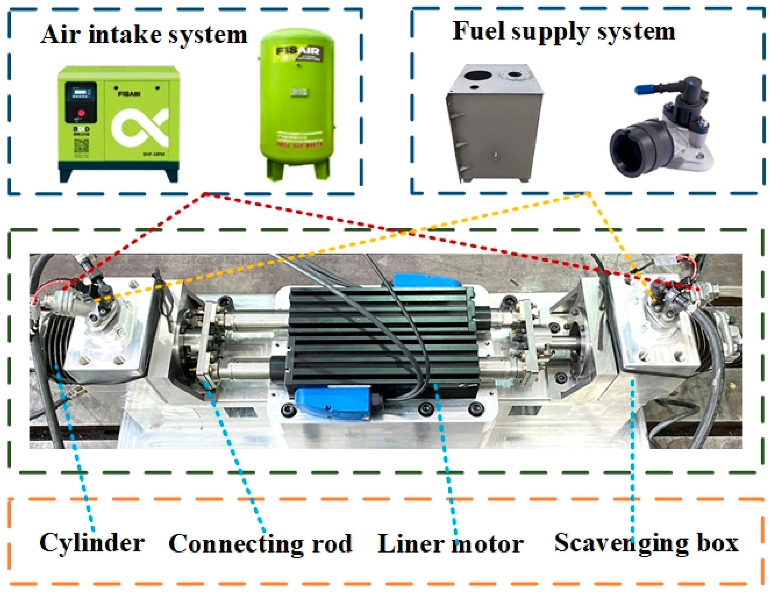
The two-cylinder spark plug ignition FPEG experimental bench designed in this paper is shown in Figure 1. The FPEG is drag-started by two motors arranged in the center, the free piston engines are symmetrically arranged on both sides of the linear motor, and the actuator replaces the crank-linkage mechanism and connecting rods of the linear motor. The free-piston engine is a two-stroke engine that uses port fuel injection for fuel supply. The main parameters of the prototype are listed in Table 1. The compression ratio is defined as the ratio of the maximum total volume of the cylinder when the piston is at bottom dead center to the minimum volume of the cylinder when the piston is at top dead center (i.e., the combustion chamber volume). The equivalent ratio refers to the ratio of the mass ratio of fuel to air in the actual supplied fuel/air mixture to the mass ratio of fuel to air in the theoretical stoichiometric mixture.
      
    
    Figure 1.
      Dual-cylinder spark ignition FPEG prototype test bench diagram.


    Table 1.
    The main parameters of the dual-cylinder ignition FPEG prototype for the experiment are as follows:
  
Figure 2 shows the schematic diagram of the experimental bench, which comprises the FPEG and other sub-systems, such as the oil supply system, air intake system, ignition system, control system, and data acquisition system. During the startup and operation stages of the prototype, the control system sends commands through the set parameters. The air compressor compresses the fresh air stored in the air cylinder, which is filtered and throttled by the filter and throttle valve before entering the scavenging air box. Simultaneously, the filtered fuel is transported by the oil pump and sprayed into the scavenging air box through the injector. The scavenging air box evenly mixes fresh air and fuel before entering the cylinder. The cylinder is then ignited by the spark plug fixed on the cylinder head. Displacement sensors mounted on the piston are coupled with the injectors and spark plugs to inject or ignite the fuel when the piston reaches a fixed displacement. The experimental rig’s data, including cylinder pressure, displacement, temperature, and air–fuel ratio, are collected by the information acquisition system. This data is used to test the prototype’s operation and facilitate subsequent data processing. The main parameters of the specific testing instruments are shown in Table 2.
      
    
    Figure 2.
      Schematic diagram of the structure and sub-systems of the experimental stand.


    Table 2.
    The technical specifications of the main test instruments are as follows.
  
2.2. Principle of Operation
For the FPEG, it is not possible to describe the ignition moment using the conventional ignition timing method due to the lack of a crank-link mechanism. Therefore, for ease of understanding, this paper chooses to use the piston displacement during ignition timing to describe the ignition state of FPEG. The intermediate displacement of the piston from BDC to TDC is specified as the zero point of displacement, labeled as 0. The displacement of the piston during upward travel is positive, and the displacement during downward travel is negative. Assuming an ignition displacement of 26 mm, this means that the spark plug fires when the piston is displaced to 26 mm from zero in the upward phase.
Figure 3 shows the practical working cycle of a two-stroke FPEG. The whole cycle can be roughly divided into a scavenge phase, a compression phase, and an in-cylinder combustion phase. Generally, the exhaust and intake phases of a two-stroke engine are referred to as the scavenging phase, which lasts from the moment the exhaust port opens to the moment the exhaust port closes.
      
    
    Figure 3.
      Two-stroke FPEG work cycle.
  
The specific operation of the scavenging phase is shown in the following sub-stages;
- (a)
 - Free scavenging phase: The exhaust port opened until the intake port opened. Following the in-cylinder combustion stage, the gas within the cylinder is at high temperature and pressure, causing the residual exhaust gases to be rapidly expelled through the exhaust port. As the exhaust port gradually opens, the pressure and temperature inside the cylinder decrease, leading to a gradual reduction in the flow rate of the residual exhaust gases.
 - (b)
 - Forced scavenging phase: The inlet port transitions from being fully open to closed. During this phase, both the intake and exhaust ports are fully open, allowing a substantial amount of fresh air from the scavenging box to flow into the cylinder, effectively sweeping out residual exhaust gases. Simultaneously, this fresh air replenishes the cylinder in preparation for the upcoming combustion phase. The forced air scavenging phase greatly enhances the efficiency of the engine’s air-sweeping process, thereby improving overall engine performance.
 - (c)
 - Final scavenging phase: The intake port remains closed while the exhaust port is closed. During this phase, fresh air from the scavenging air box is not injected into the cylinder. As the piston moves towards TDC, the cylinder gas is also compressed, and the pressure inside the cylinder increases. Once this pressure surpasses that in the exhaust, the gas in the cylinder is expelled through the exhaust port.
 
When the scavenging phase is complete and the exhaust port is closed, the FPEG proceeds to the compression phase. The cylinder gas is compressed under the action of the piston, and the pressure in the cylinder rises continuously. When the piston is about to reach TDC, the spark plug fires to start the in-cylinder combustion stage.
2.3. The CFD Model of FPEG and Simulation Strategies
Based on the dual-cylinder spark plug ignition FPEG prototype studied in this paper, a three-dimensional combustion simulation model of FPEG is established based on the three-dimensional CFD simulation software Converge 3.0, as shown in Figure 4. Among these, the M inlet is the main inlet port, while the R intake is the rear inlet port.
      
    
    Figure 4.
      Three-dimensional model of FPEG.
  
The numerical model developed in this study incorporates a series of reasonable simplifications while ensuring accurate capture of core physical mechanisms. First, in geometric modeling, we neglected minute features in the solid model, such as chamfers, fillets, and surface roughness. This simplification is based on preliminary analysis indicating that these features exert negligible influence on the overall mechanical response, while significantly reducing mesh complexity and computational cost. Additionally, in boundary condition settings, we employ a quasi-static assumption, simplifying complex transient conditions in real environments into equivalent steady-state variables. This approach enhances computational efficiency and model convergence while effectively revealing the fundamental patterns of the investigated problem. The specific parameters such as boundary conditions of the models used in this study are shown in Table 3.
       
    
    Table 3.
    Boundary conditions for free-piston engine.
  
Meanwhile, the simulations are based on the following mathematical models and reaction mechanisms: Turbulence simulation employs the RNG *k*-ε model, which effectively accounts for turbulent rotational effects and exhibits high predictive accuracy for high velocity gradient flow fields []. For the combustion model, the SAGE model can provide a detailed chemical reaction model, which imposes no restrictions on the number of reaction components or steps, enabling a detailed description of reaction pathways and component concentration evolution during combustion []. The SAGE combustion model is coupled with a detailed chemical reaction mechanism that comprises 74 components and 312 reactions []. Furthermore, to effectively handle near-wall flow and heat transfer while maintaining computational accuracy, the wall function method is employed []. For NOx emissions analysis, the Extended Zeldovich model is used []. A series of studies have verified the mathematical model and reaction mechanism used in the 3D model, as shown in Table 4.
       
    
    Table 4.
    Mathematical models and chemical mechanism.
  
Since there is no crank-link mechanism in FPEG, so this paper chooses time-based modeling in Converge software.
This paper primarily investigates dual ignition strategies: synchronous ignition (fixed ignition interval) and asynchronous ignition (variable ignition interval), with specific ignition timings set (as shown in Table 5), aiming to analyze their effects on FPEG performance. The experiment used the initial condition “L-26 mm/R-24 mm” as the benchmark for performance comparison. Based on this benchmark, researchers systematically varied the ignition parameters: For the synchronous strategy, they maintained constant intervals for the spark plug ignition while either collectively advancing (e.g., +4 mm, +2 mm) or retarding (e.g., −2 mm, −4 mm, −6 mm) the overall ignition timing. This approach aimed to observe its impact on combustion processes. For the asynchronous strategy, one of the ignition positions was fixed, and the other position was varied. This adjustment created different ignition intervals between the left and right spark plugs. Specific phase differences of −4 mm, −2 mm, +2 mm, and +4 mm were established, with negative values indicating that the left side ignited first and positive values indicating that the right side ignited first. This setup aimed to investigate the effects of differing ignition intervals and flame propagation. It is particularly noteworthy that the baseline condition inherently has a 2 mm ignition phase difference. As a result, one synchronous strategy (A3) and one asynchronous strategy (B3) within the experimental framework share the same ignition timing.
       
    
    Table 5.
    Specific ignition timing of double spark plugs.
  
2.4. Model Verification
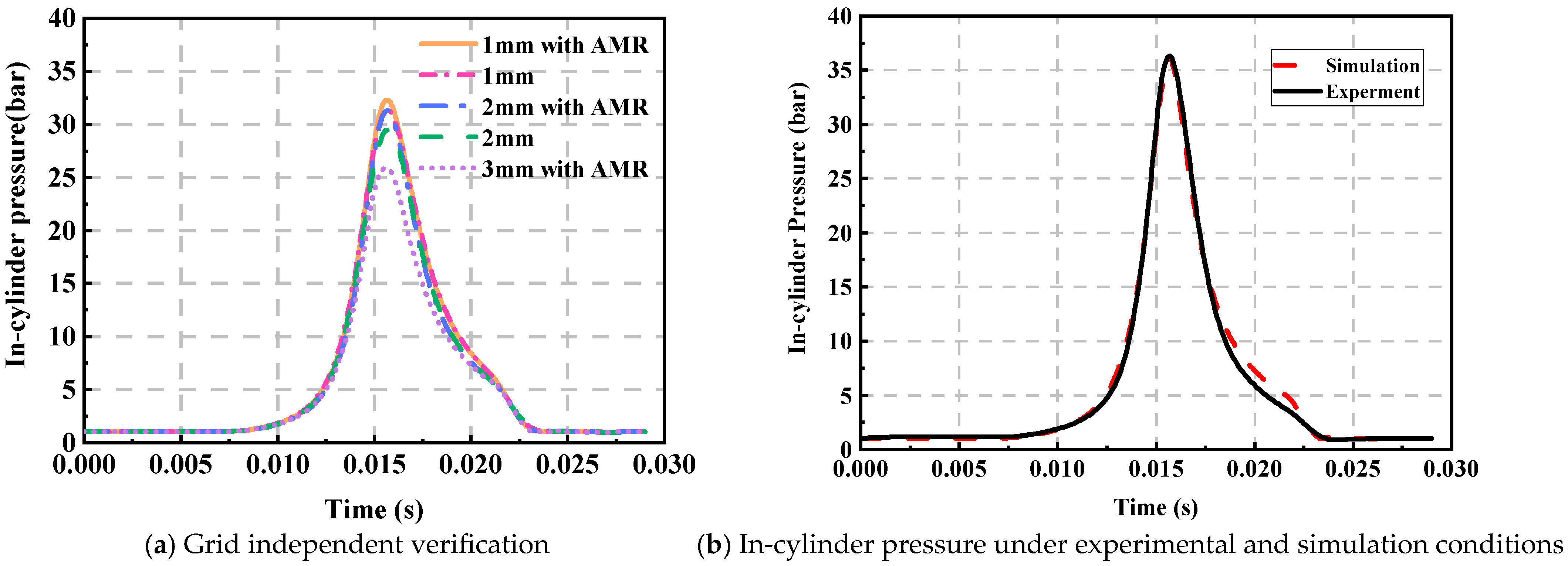
The mesh size critically influences simulation outcomes, where finer grids provide superior accuracy at the expense of a substantial increase in computational time, while coarser grids reduce duration but introduce significant errors, necessitating a mesh independence study. This work evaluates three base grid sizes for cylinder pressure analysis and further verifies them using adaptive meshes generated by Converge’s Adaptive Mesh Refinement (AMR). Figure 5a indicates that results from the 2 mm and 3 mm base grids with AMR show notable deviations from the 1 mm AMR reference, whereas the discrepancy between the 1 mm and 2 mm AMR cases is minimal. Consequently, the 2 mm grid with AMR was chosen as the optimal compromise between computational accuracy and cost.
      
    
    Figure 5.
      Grid independent verification and in-cylinder pressure verification.
  
To further illustrate the reliability of the free-piston engine model, the mean cylinder pressure was verified based on experimental data. The in-cylinder pressure curves in the experiment and simulation are shown in Figure 5, from which it can be seen that the peak cylinder pressure and the corresponding phases, as well as the trend of pressure, are highly consistent. Only in the downward phase of the piston due to the difference in sealing conditions, there is an acceptable error, and the vast majority of regions’ errors do not exceed 5%. The results show that the simulation model established in this paper can accurately simulate the in-cylinder mixture formation and combustion process and meet the subsequent simulation study. To ensure the accuracy of subsequent studies, the boundary conditions and initial conditions used in the following research are presented in Table 3 and Table 5.
3. Results and Discussion
3.1. Effect of Synchronous and Asynchronous Changes on Combustion Characteristics
Figure 6a presents the variations in in-cylinder pressure and heat release rate (HRR) for different ignition positions within the synchronized dual spark plug scheme. This setup maintains the ignition interval between spark plugs at 2 mm. As the ignition position of the R-side spark plug is advanced from 30 mm to 22 mm before the TDC, a marked increase in peak in-cylinder pressure is observed, along with an advancement in the corresponding piston position at which peak pressure occurs. However, further advancing the ignition position leads to a decrease in peak pressure. This decrease occurs because an earlier ignition point leads to a less homogeneous air–fuel mixture. This inhomogeneity, in turn, results in lower in-cylinder pressure and temperature, which impairs the initial ignition and flame kernel development. When the ignition position is set at 30 mm, the peak pressure reaches only 31 bar, mainly due to the ignition occurring too late, causing the peak of the HRR to be delayed. In this case, the majority of heat release takes place well after TDC, which hampers efficient heat release and thus diminishes the engine’s ability to drive the piston effectively. Conclusively, appropriately advancing the ignition position can enhance combustion within the cylinder, optimize the timing of the peak HRR, and promote an increase in in-cylinder pressure.
      
    
    Figure 6.
      In-cylinder pressure and heat release rate (HRR) under different schemes.
  
Figure 6b illustrates the variation in in-cylinder pressure and HRR for different ignition positions within the asynchronous dual spark plug scheme. In this scheme, the ignition interval between the spark plugs is adjusted at increments of −4 mm, −2 mm, 2 mm, and 4 mm, while maintaining all other parameters constant. The findings demonstrate that the ignition interval influences in-cylinder pressure. Generally, advancing the ignition position tends to elevate the peak in-cylinder pressure. Notably, in the B3 scheme, where the interval is 2 mm, the peak pressure reaches its highest value at approximately 56.4 bar. In contrast, in the B2 scheme, where the interval is −2 mm, the peak pressure only attains 52.7 bar, reflecting a decrease of 6.56%. This indicates that advancing the ignition position of the R-side spark plug has a more pronounced effect on in-cylinder pressure.
Further comparison of the difference in in-cylinder pressure between schemes shows that the ignition configuration significantly affects the combustion process even at the same ignition position. Specifically, in the B1 configuration, the ignition position of the L-side spark plug is advanced. Comparison to the B2 configuration, the ignition interval is extended, effectively increasing the in-cylinder pressure. This may be because a larger ignition interval improves the interaction between the airflow and the fire core, resulting in a more uniform combustion process, which in turn boosts the pressure. However, the results of the B3 and B4 schemes are different. In the case of R-side ignition advance, the larger ignition interval instead led to a decrease in in-cylinder pressure. This phenomenon may be related to the direction of airflow in the cylinder. Since the airflow usually flows from the right side to the left side, a large ignition interval may make the pushing effect of the airflow interfere with the combustion prematurely, leading to premature combustion of the mixture on the right side, thus affecting the uniformity of combustion. In that case, the fire nuclei on the left and right sides may meet prematurely, resulting in incomplete local combustion or even negative effects, which may have an adverse impact.
Figure 7 presents the in-cylinder peak pressure corresponding to different ignition strategies. By adjusting the ignition position, the peak pressure can reach up to 62.5 bar, representing a 10.8% increase compared to the base condition. Compared to the asynchronous ignition configuration, the synchronous ignition configuration with the same ignition interval exhibits greater variation under the influence of ignition timing, with a noticeable increasing trend as the ignition timing is advanced. In contrast, the asynchronous strategy with different ignition intervals is influenced by the in-cylinder airflow, resulting in significant nonlinear characteristics in pressure and differs from the trend of the synchronous.
      
    
    Figure 7.
      Peak in-cylinder pressure under different schemes.
  
It is essential to analyze the combustion process within the cylinder to facilitate a more intuitive comparison of the speed of heat release between the different spark plug schemes. The whole combustion process is commonly divided into three stages: ignition delay, flame propagation, and flame termination. The ignition delay period refers to the time from the spark position (SP) to 10% of the mass burn fraction (MBF), known as SP-10% combustion duration. The flame propagation period covers the time from 10% MBF position to 90% MBF position. The flame termination period refers to the duration in which the remaining fuel continues to burn in the cylinder. The duration from 10% MBF position to 50% MBF position is also used to characterize the time for the flame front to reach the edge of the combustion chamber in the simulation experiments.
As illustrated in Figure 8, the ignition delay periods of two ignition strategies are compared. Due to the staggered ignition position, the ignition strategies in scenarios A3 and B3 are identical. The figure reveals that as the ignition position and intervals are advanced, both the synchronous and asynchronous ignition schemes show an increasing trend in SP-10% combustion duration. This phenomenon primarily results from the earlier formation of the fire nucleus triggered by the advancement of the ignition position. At this stage, the piston is still on its upward trajectory, and the temperature inside the cylinder remains low, the mixture distribution inside the cylinder is poor, which hinders the development and propagation of the flame, consequently leading to a longer ignition delay period. The different performances observed under 2 mm and 4 mm ignition intervals in the asynchronous scheme (such as B2, B3 vs. B1, B4) can be explained by the effects of in-cylinder airflow and the negative impact of flame kernel collisions. Specifically, in the B1 and B2 schemes, the flame propagation needs to overcome disturbances caused by the in-cylinder airflow, while in the B3 and B4 schemes, the airflow aids the process. However, in the B3 and B4 schemes, the collision between the two flame cores may result in more severe negative effects, further impacting the combustion process.
      
    
    Figure 8.
      Ignition delay period under different schemes.
  
Figure 9 illustrates the variations in the time of 10–50% combustion duration and 10–90% combustion duration under different ignition strategies. As shown in Figure 9a, under the synchronous ignition strategy, both the 10–50% combustion duration and 10–90% combustion duration initially decrease and then increase as the ignition location advances. This observed phenomenon may be attributed to the earlier ignition igniting more fuel before reaching the TDC, while the piston is still in the upward motion, leading to an increase in cylinder pressure. This elevated pressure, in turn, partially hampers further flame propagation. Additionally, the faster initial flame expansion may cause the flame front to collide, and the interaction between flame cores could influence the flame propagation process. In contrast, Figure 9b indicates that under the asynchronous ignition strategy, there is an increase in the 10–50% combustion duration and 10–90% combustion duration. While the 10–50% combustion duration and 10–90% combustion duration are higher than the synchronous one, the differences gradually diminish with changes in the ignition configuration. For the synchronous strategy, advancing the ignition position results in a maximum reduction in combustion duration of 1.5 ms, while in the asynchronous strategy, the reduction is only 0.135 ms due to the different setups of the ignition scheme.
      
    
    Figure 9.
      Combustion duration under different schemes.
  
Figure 10 shows the power and thermal efficiency under different ignition strategies. In the synchronous ignition strategy, continuous adjustments to the ignition position allowed Case A4 to achieve the highest indicated thermal efficiency (37.5%) and indicated power (3.05 kW), reflecting an 11.3% improvement over previous studies []. In this case, both advancing and delaying the ignition position result in a deterioration of performance. Advancing the ignition position causes the cylinder pressure to rise too quickly, leading to significant negative work during the compression phase. On the other hand, delaying the ignition position slows the combustion rate, extends the combustion duration, and decreases the peak pressure, all of which contribute to a reduction in both indicated thermal efficiency and indicated power. In the asynchronous ignition strategy, advanced L-side spark plug ignition positions, such as B1 and B2, show better performance. Among them, B2 achieves an indicated thermal efficiency of 37.6% and an indicated power of 3.06 kW, which is attributed to the shorter combustion duration.
      
    
    Figure 10.
      Indicated power and indicated thermal efficiency under different schemes.
  
3.2. Effects of Synchronous and Asynchronous Ignition Strategies on Flame Development and Flame Propagation
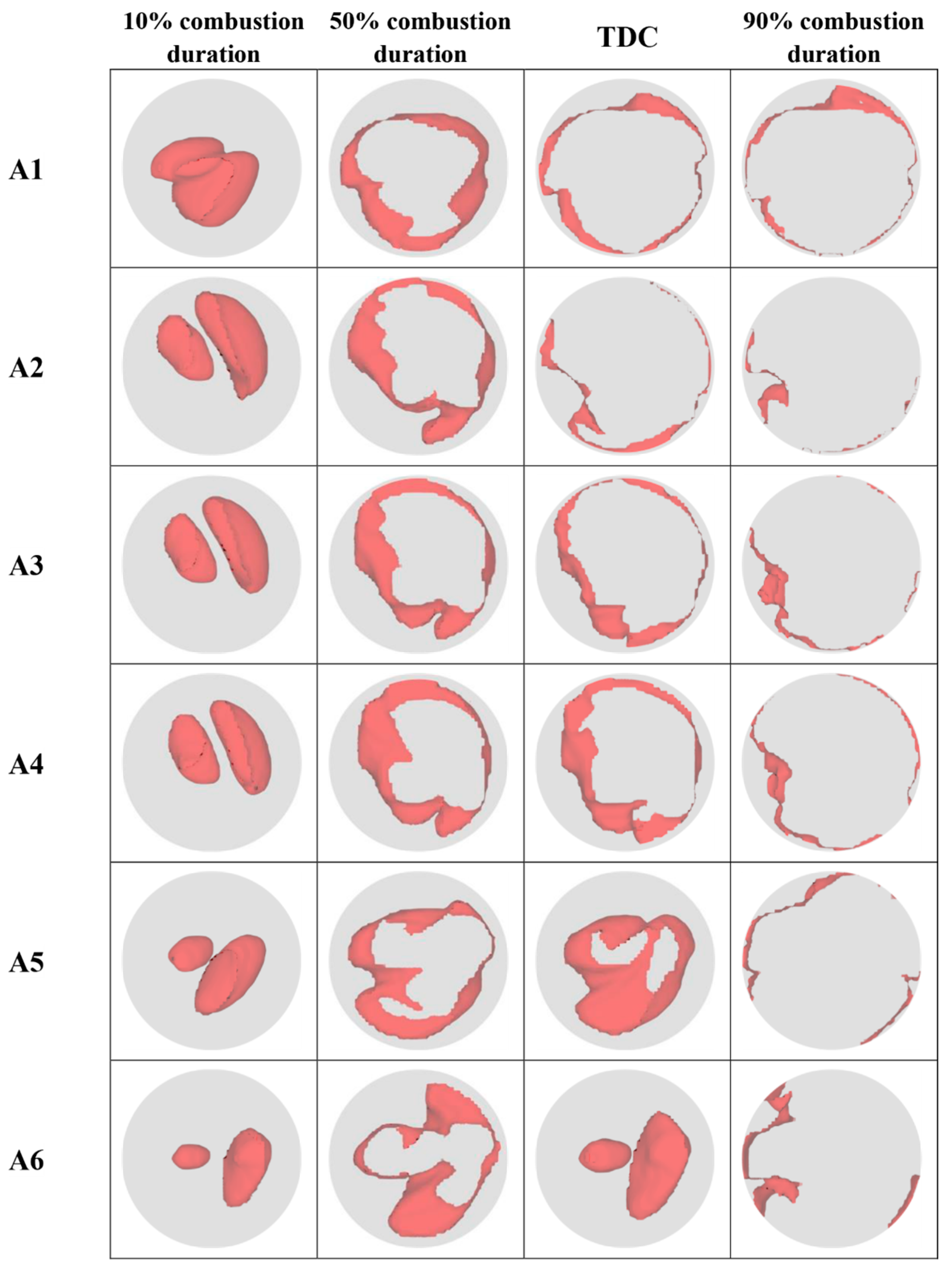
To study the process of flame formation and development in the cylinder more intuitively, Figure 11 and Figure 12 illustrate the combustion diffusion cloud maps of the FPEG under different strategies. In these figures, the red-shaded areas represent the position of the 2000 K flame front and its propagation throughout the combustion chamber. Technically, using dual spark plugs inevitably leads to forming two independent flame cores, each developing through the combustion of the fuel–air mixture. As a result, the combustion area between the unburned and burned gases increases, significantly accelerating the heat and mass transfer between the flame fronts, thereby enhancing the combustion rate and promoting the faster spread of the flame within the combustion chamber. The results show that the two independent flame cores formed by the dual spark plugs move along with the in-cylinder flow regardless of the configuration. The turbulent flow strongly distorts and stretches the two independent flame fronts. This is primarily due to the design of the FPEG’s intake and exhaust ports (as shown in Figure 4), which generates a strong counterclockwise recirculating motion within the cylinder, increasing the swirl ratio around the combustion chamber and further facilitating the growth and development of the flame cores.
      
    
    Figure 11.
      Combustion process corresponding to the synchronous change.


    Figure 12.
      Combustion process corresponding to the asynchronous change.
  
Based on the synchronized and asynchronous ignition strategies in this study, we observe the ignition delay period (10% combustion duration), combustion centroid (50% combustion duration), the flame propagation cessation point (90% combustion duration) (i.e., 10%, 50%, and 90% of the combustion mass fraction), and the variations and characteristics of the flame front at the TDC.
Figure 11 illustrates the flame propagation process when the ignition positions vary synchronously. At 10% combustion duration, only the flame front from configuration A1 comes into contact, leading to an interaction between the flame fronts, which results in interference and causes a longer ignition delay period (as shown in Figure 8). In addition, the flame fronts in the other configurations exhibit significant stretching, distortion, and wrinkling at this stage, which increases the combustion area and accelerates the combustion rate. Since the initial conditions are the same, the size of the flame cores formed by the spark plugs is identical at the initial ignition stage. However, due to the different ignition positions, the radius of the flame core on the right side is larger than that on the left side in case A1–A6. Furthermore, influenced by the in-cylinder airflow, the flame mainly develops from the right side toward the left, with the right-side flame core gradually engulfing the left side. At 50% combustion duration, except for A6, the other cases exhibit nearly circular flame propagation, with a larger contact area between the flame and the unburned air–fuel mixture in the cylinder. As the combustion progresses, the flame propagation speed increases, which helps achieve rapid combustion.
At TDC, the flame fronts in A1–A4 have already contacted the cylinder wall and been quenched, further accelerating the combustion rate. In contrast, the two flame cores in A6 have not yet interacted, and the 50% combustion duration occurs significantly earlier than TDC, which causes a substantial portion of the fuel to start burning only after reaching the top dead center, thus slowing down the combustion rate and reducing the concentration of heat release within the cylinder. As shown in Figure 9b, the 10–50% and 10–90% combustion durations for Case A6 are significantly higher than the other options.
Figure 12 shows the flame propagation process when the ignition positions vary asynchronously. At 10% combustion duration, only the two flame cores in case B3 have not yet made contact, while the flame front areas in B1 and B2 are nearly identical. Comparing B1 and B4, it is proved that advancing the ignition position of the R-side spark plug can better play the role of promoting the in-cylinder airflow and further accelerate the combustion of the in-cylinder premix. Notably, although advancing the ignition on the right side enlarges the flame propagation area in the early ignition stage and accelerates combustion, the flame front in the later stages of combustion expands more slowly, leading to a longer overall combustion duration. As shown in Figure 9a, the B4 scheme has a shorter 10–50% combustion duration but a longer 50–90% combustion duration, resulting in an overall increase in combustion duration compared to the B1 scheme. At 50% combustion duration and TDC, the flame contour in the asynchronous ignition configurations displays more uniform propagation characteristics, with the flame front becoming nearly circular, indicating a more uniform and stable flame propagation process.
3.3. Effects of Synchronous and Asynchronous Changes on Emissions
During the combustion process, the in-cylinder temperature is closely related to the generation of emissions. As shown in Figure 13, the mean in-cylinder temperatures are given under different schemes. Regardless of whether the ignition position changes synchronously or asynchronously, advancing the ignition position leads to a higher peak in-cylinder temperature, but the increase tends to decrease gradually. In the synchronous scheme, the peak in-cylinder temperature reaches a maximum of 2700 k at case A2, at which point further advancement of the ignition position decreases the peak temperature instead. In contrast, under the asynchronous ignition scheme, the change in peak temperature follows an opposite trend concerning the ignition position. Specifically, as the ignition position is advanced, Case B1 shows an increase in peak temperature compared to B2, while Case B4 shows a decrease compared to B3. This may be due to a combination of the negative effects of cylinder airflow effects and fire core collisions as described earlier. Additionally, there is a strong correlation between the peak temperature and the corresponding piston position. This is because the peak temperature represents the degree of heat release in the cylinder, higher peak temperatures indicate more concentrated heat release, so the piston is closer to the TDC.
      
    
    Figure 13.
      Mean in-cylinder temperature under different strategies.
  
In this paper, the hot-state NOx generation model (Extended Zeldovich Model), is used to study the formation of NOx inside the cylinder. The main reaction equation is as follows:


Both Type (1) and Type (3) are strongly endothermic reactions that can only proceed at high temperatures of 1800 K; hence, they are also referred to as thermal NOx formation models. In the hot-state NOx generation model, the cylinder temperature directly affects the formation of NOx. Figure 14 shows the generation curves of NOx over time under different conditions. Although the mole fraction of NOx increases rapidly in all cases before remaining essentially constant, the peak values of the NOx mass fraction differ. As shown in Figure 14a, as the ignition position advances, the combustion inside the cylinder accelerates and the exothermic heat of the combustion reaction increases in a short period, leading to an increase in the cylinder temperature. As a result, the NOx generation rate increases, and the NOx mole fraction increases, reaching a peak (0.444%) under A2 operating conditions. However, when the ignition position was delayed to 30 mm, the temperature in the cylinder decreased to a minimum value of 2100 K, while the NOx mole fraction decreased to a minimum (0.107%). It can be attributed to the fact that the delayed ignition leads to an incomplete combustion process, with the temperature peaking approximately 9.2 mm after the upper stop, resulting in an environment that fails to achieve sufficiently high-temperature conditions. As a result, NOx production is significantly reduced at lower temperatures. This can also be found in the comparison of B2 and B4.
      
    
    Figure 14.
      NOx mole fraction versus time.
  
Whereas, as shown in Figure 14b, the trend of in-cylinder NOx generation under the asynchronous scheme is similar to that of the synchronous. As the ignition interval changes, the peak in-cylinder temperature and the NOx mole fraction change. Furthermore, compared to the synchronous scheme, the NOx generation rate in the asynchronous scheme is more consistent, with a difference of only 0.032%. It is worth noting that, although Figure 13. shows that the peak cylinder temperatures of A4 and B4 are almost the same, the NOx mole fraction differs. This is largely because combustion temperature is not the only factor affecting NOx emissions; the reaction time inside the cylinder also plays a role []. The extended Zeldovich mechanism primarily governs NOx emissions. This mechanism involves a series of elementary reactions between atmospheric nitrogen and oxygen, characterized by high activation energies and thus high temperature sensitivity. According to the reaction mechanism of high-temperature NOx, the three essential factors for NOx formation are high temperature, oxygen enrichment, and sufficient reaction time. Since NOx formation occurs much more slowly than other pollutants (such as CO, CO2, and HC), and the in-cylinder combustion process in FPEG engines is rapid, NOx often fails to reach the equilibrium concentration of the reaction equation by the end of combustion. Therefore, under identical temperature conditions, longer reaction times naturally result in greater NOx production. As a result, at the same high temperature, a longer reaction time leads to greater NOx formation. The combustion duration in the B4 scheme is longer, providing more reaction time, thus leading to higher NOx emissions. In contrast, A4 has a faster response with a shorter reaction time, less conducive to NOx generation.
The reaction OH + CO ⇔ H + CO2 is the main step in CO oxidation [,], which is an exothermic reaction in the combustion of hydrocarbon fuels. CO is oxidized to CO2 in the later stages of combustion, releasing a significant amount of heat. Therefore, during combustion, CO is mainly produced as an intermediate product and can be intuitively represented by its mole fraction to reflect the combustion intensity. Figure 15 presents the CO generation curves over time under different conditions. As shown in Figure 15a, the highest peak CO mole fraction occurs in Case A2 reached 1.89%, which also corresponds to the highest peak pressure and peak temperature inside the cylinder, indicating the most intense combustion at this condition. Compared to other cases, Case A6 exhibits a lower CO mole fraction, which can be attributed to the delayed ignition position, leading to a milder combustion reaction and a reduction in both cylinder pressure and temperature. From Figure 14b, it can be observed that the CO mole fraction variation in the asynchronous scheme is relatively small, reflecting the equilibrium and stability of the combustion process. The curves for B1 and B4 are almost identical, and the peak values for B2 and B3 are also nearly the same, with only a phase difference between them. In addition, the CO measured at valve opening is considered the actual exhaust emissions. Under A6 conditions, the actual CO value is 0.3%, significantly higher than in other operating conditions. For asynchronous conditions, except for B3, the values are approximately 0.104%.
      
    
    Figure 15.
      CO mole fraction versus time.
  
By examining the in-cylinder CO distribution under different ignition strategies, as shown in Figure 16, the variations in CO distribution within the cylinder become more intuitive. As shown in Figure 16a, the high-concentration CO region (red) at 2 mm ATDC gradually contracts toward the spark plug as ignition timing is retarded, with its distribution range significantly decreasing. This phenomenon primarily stems from locally sub-stoichiometric conditions (equivalence ratio < 1.0) resulting from the uneven spatial distribution of the fuel–air mixture during actual combustion. Under oxygen-deficient conditions, incomplete combustion occurs, leading to concentrated CO formation in the flame propagation core region—specifically around the spark plug. By 10 mm ATDC, noticeable residual CO regions remain observable in modes A4–A6, indicating incomplete combustion and weak late-stage oxidation reactions that fail to effectively eliminate earlier-formed products of incomplete combustion. In contrast, Figure 16b shows that asynchronous ignition enhances in-cylinder gas flow, improving fuel–air mixing uniformity and thereby suppressing the formation of locally lean or rich zones. Consequently, CO exhibits greater consistency than the synchronous scheme at both 2 mm BTDC and 10 mm ATDC. More critically, asynchronous ignition concentrates primary exothermic processes near TDC, creating combustion temperatures and oxidation conditions more favorable for late-stage CO oxidation. By 10 mm ATDC, CO oxidation within the cylinder is largely complete, with overall molar fractions maintained at low levels (predominantly blue regions).
      
    
    Figure 16.
      In-cylinder CO distribution under different strategies.
  
Finally, Figure 17 presents the HC mole fraction curves over time under different conditions. The results show that the HC mole fraction curve is a good reflection of the combustion consumption rate inside the cylinder, which in turn indicates the combustion speed. As combustion progresses, regardless of the scheme used, the HC mole fraction rapidly decreases after the ignition point. In the later stages of combustion, except for Case A6, the HC emissions for the other schemes are essentially the same. Additionally, during combustion, the HC emissions are more consistent in the asynchronous schemes compared to the synchronous ones.
      
    
    Figure 17.
      HC mole fraction of HC versus time.
  
4. Conclusions
In this research, a detailed three-dimensional kinetic model was built based on a real FPEG combustion chamber. Numerical simulations of the FPEG were carried out using CFD techniques combined with detailed combustion mechanisms and verified in comparison with experimental data. On this basis, the effect of dual-spark-plug FPEG on the combustion process under synchronous and asynchronous changes was investigated to improve the combustion performance of the FPEG system. The main research results can be summarized as follows;
- (1)
 - Whether employing synchronous or asynchronous ignition, changing the ignition position considerably impacts the in-cylinder pressure. Under Case A2, the peak pressure achieved by the synchronous scheme can reach up to 62.5 bar, reflecting a 10.8% improvement over the base case and showing a significant growth trend as the ignition position is advanced. In contrast, the asynchronous scheme exhibits significant nonlinear characteristics in its pressure variations, due to the negative effects of in-cylinder airflow action and fire core collision, and the trend is quite different from that of the synchronous ignition scheme.
 - (2)
 - As the ignition position continues to advance, the ignition delay period for both the synchronous and asynchronous schemes shows an increasing trend. In the synchronous ignition scheme, the combustion duration shows a trend of decreasing and then increasing, with a maximum shortening of 1.5 ms. The combustion duration of the asynchronous scheme increases compared with that of the synchronous, and the difference in the cases gradually decreases with the change in the ignition position, with a maximum shortening of 0.135 ms. When the ignition is set to L-24 mm/R-26 mm, the indicated thermal efficiency reaches a peak of 37.6%.
 - (3)
 - Regardless of the ignition scheme employed, the two separate flame cores formed by the spark plugs are affected by the ignition arrangement and the strong counterclockwise return flow within the cylinder, and the flame cores gradually develop from the right side to the left side. In this process, the right-side flame core will gradually engulf the left-side flame core. At 50% combustion duration and TDC moment, the flame cloud map of the asynchronous ignition scheme shows more uniform propagation characteristics, and the flame front tends to be round.
 - (4)
 - Delaying the synchronized ignition to L-32 mm/R-30 mm, the NOx mole fraction reaches its lowest value due to the lower temperature in the cylinder. However, CO and HC emissions increased significantly due to incomplete combustion. Compared to the synchronous schemes, the asynchronous schemes showed less difference in emissions and did not exhibit significant emission fluctuations, and the overall emissions were low.
 
Author Contributions
Conceptualization, X.H. and H.F.; methodology, X.H.; software, C.L. and L.X.; validation, C.L., Q.L. and Y.W.; formal analysis, B.J.; investigation, H.F.; resources, B.J. and L.X.; writing—original draft preparation, X.H.; writing—review and editing, C.L.; supervision, B.J.; project administration, H.F. and Y.W.; All authors have read and agreed to the published version of the manuscript.
Funding
This research received no external funding.
Institutional Review Board Statement
Not applicable.
Informed Consent Statement
Not applicable.
Data Availability Statement
The original contributions presented in the study are included in the article, and further inquiries can be directed to the corresponding author.
Conflicts of Interest
The authors declare no conflicts of interest.
Abbreviations
The following abbreviations are used in this manuscript:
      
| FPEG | Free piston engine generator | 
| OSFPG | Opposed single-cylinder free piston generator | 
| CFD | Computational fluid dynamics | 
| TDC | Top dead center | 
| BDC | Bottom dead center | 
| ATDC | After top dead center | 
| NOx | Nitrogen oxide | 
| HCCI | Homogeneous charge compression ignition | 
| SDI | Semi-direct injection system | 
| PFI | Port fuel injection | 
| HC | Hydrocarbon | 
| HRR | Heat release rate | 
| AMR | Adaptive mesh refinement | 
| SP | Spark position | 
| MBF | Mass burn fraction | 
References
- Gao, J.; Chen, H.; Li, Y.; Chen, J.; Zhang, Y.; Dave, K.; Huang, Y. Fuel consumption and exhaust emissions of diesel vehicles in worldwide harmonized light vehicles test cycles and their sensitivities to eco-driving factors. Energy Convers. Manag. 2019, 196, 605–613. [Google Scholar] [CrossRef]
 - Meng, H.; Ji, C.; Xin, G.; Yang, J.; Chang, K.; Wang, S. Comparison of combustion, emission and abnormal combustion of hydrogen-fueled Wankel rotary engine and reciprocating piston engine. Fuel 2022, 318, 123675. [Google Scholar] [CrossRef]
 - Gao, J.; Tian, G.; Sorniotti, A.; Karci, A.E.; Di Palo, R. Review of thermal management of catalytic converters to decrease engine emissions during cold start and warm up. Appl. Therm. Eng. 2019, 147, 177–187. [Google Scholar] [CrossRef]
 - Guo, C.; Zuo, Z.; Feng, H.; Jia, B.; Roskilly, T. Review of recent advances of free-piston internal combustion engine linear generator. Appl. Energy 2020, 269, 115084. [Google Scholar] [CrossRef]
 - Guo, C.; Feng, H.; Jia, B.; Zuo, Z.; Guo, Y.; Roskilly, T. Research on the operation characteristics of a free-piston linear generator: Numerical model and experimental results. Energy Convers. Manag. 2017, 131, 32–43. [Google Scholar] [CrossRef]
 - Feng, H.; Guo, C.; Jia, B.; Zuo, Z.; Guo, Y.; Roskilly, T. Research on the intermediate process of a free-piston linear generator from cold start-up to stable operation: Numerical model and experimental results. Energy Convers. Manag. 2016, 122, 153–164. [Google Scholar] [CrossRef]
 - Hung, N.B.; Lim, O. A review of free-piston linear engines. Appl. Energy 2016, 178, 78–97. [Google Scholar] [CrossRef]
 - Hanipah, M.R.; Mikalsen, R.; Roskilly, A.P. Recent commercial free-piston engine developments for automotive applications. Appl. Therm. Eng. 2015, 75, 493–503. [Google Scholar] [CrossRef]
 - Guo, C.; Zuo, Z.; Feng, H.; Roskilly, T. Advances in free-piston internal combustion engines: A comprehensive review. Appl. Therm. Eng. 2021, 189, 116679. [Google Scholar] [CrossRef]
 - Zhao, Z.; Wang, S.; Zhang, S.; Zhang, F. Thermodynamic and energy saving benefits of hydraulic free-piston engines. Energy 2016, 102, 650–659. [Google Scholar] [CrossRef]
 - Atkinson, C.M.; Petreanu, S.; Clark, N.N.; Atkinson, R.J.; McDaniel, T.I.; Nandkumar, S.; Famouri, P. Numerical Simulation of a Two-Stroke Linear Engine-Alternator Combination. In Proceedings of the International Congress & Exposition, Detroit, MY, USA, 1–4 March 1999; pp. 1416–1430. [Google Scholar]
 - Mikalsen, R.; Roskilly, A.P. A review of free-piston engine history and applications. Appl. Therm. Eng. 2007, 27, 2339–2352. [Google Scholar] [CrossRef]
 - Mikalsen, R.; Roskilly, A.P. A computational study of free-piston diesel engine combustion. Appl. Energy 2009, 86, 1136–1143. [Google Scholar] [CrossRef]
 - Nigro, A.; Algieri, A.; De Bartolo, C.; Bova, S. Fluid dynamic investigation of innovative intake strategies for multivalve internal combustion engines. Int. J. Mech. Sci. 2017, 123, 297–310. [Google Scholar] [CrossRef]
 - Zhang, S.; Duan, X.; Liu, Y.; Guo, G.; Zeng, H.; Liu, J.; Lai, M.-C.; Talekar, A.; Yuan, Z. Experimental and numerical study the effect of combustion chamber shapes on combustion and emissions characteristics in a heavy-duty lean burn SI natural gas engine coupled with detail combustion mechanism. Fuel 2019, 258, 116130. [Google Scholar] [CrossRef]
 - Feng, H.; Lai, K.; Zheng, Z.; Lin, S.; Wu, X.; Tang, Q. Effects of methanol direct injection and high compression ratio on improving the performances of a spark-ignition passenger car engine. Fuel 2024, 357, 130052. [Google Scholar] [CrossRef]
 - Yilmaz, I.T. The effect of hydrogen on the thermal efficiency and combustion process of the low compression ratio CI engine. Appl. Therm. Eng. 2021, 197, 117381. [Google Scholar] [CrossRef]
 - Calam, A. An experimental research on the determination of the combustion characteristics of ABE fuel in a port injection HCCI engine. Energy Convers. Manag. 2024, 321, 119087. [Google Scholar] [CrossRef]
 - Wang, B.; Xie, F.; Hong, W.; Du, J.; Chen, H.; Su, Y. The effect of structural parameters of pre-chamber with turbulent jet ignition system on combustion characteristics of methanol-air pre-mixture. Energy Convers. Manag. 2022, 274, 116473. [Google Scholar] [CrossRef]
 - Wang, B.; Xie, F.; Hong, W.; Du, J.; Chen, H.; Li, X. Extending ultra-lean burn performance of high compression ratio pre-chamber jet ignition engines based on injection strategy and optimized structure. Energy 2023, 282, 128433. [Google Scholar] [CrossRef]
 - Duan, X.; Zhang, S.; Liu, Y.; Li, Y.; Liu, J.; Lai, M.-C.; Deng, B. Numerical investigation the effects of the twin-spark plugs coupled with EGR on the combustion process and emissions characteristics in a lean burn natural gas SI engine. Energy 2020, 206, 118181. [Google Scholar] [CrossRef]
 - Chang, K.; Ji, C.; Wang, S.; Yang, J.; Meng, H.; Wang, H.; Xin, G. Comparative study on different spark plug positions of a rotary engine with gasoline port and direct injection. Fuel 2022, 310, 122376. [Google Scholar] [CrossRef]
 - Duan, H.; Hu, W.; Wang, J.; Yin, X.; Hu, E.; Zeng, K. Effects of diesel pilot-injection strategy on a methanol/diesel dual-direct injection engine. Appl. Therm. Eng. 2024, 261, 125106. [Google Scholar] [CrossRef]
 - Yu, J.; Zhou, F.; Fu, J.; Huang, D.; Wu, C.; Liu, J. Research on the influence of injection strategies on the in-cylinder combustion process and emissions of methanol. Biomass Bioenergy 2024, 188, 107340. [Google Scholar] [CrossRef]
 - Xu, L.; Wei, Y.; Liu, C.; Jia, B.; Zhang, Z.; Qin, S.; Hu, X.; Feng, H.; Zuo, Z. Research on the implementation of free piston engine generator at various compression ratios and combustion performance of multiple fuels. Energy 2024, 313, 133690. [Google Scholar] [CrossRef]
 - Wang, J.; Zhou, J.; Kong, L.; Qin, Z.; Zhang, H.; Li, T.; Xu, Z.; Zhang, W. Effect of injection position on in-cylinder airflow motion and combustion in a diesel-ignited hydrogen free-piston engine. Case Stud. Therm. Eng. 2025, 74, 106960. [Google Scholar] [CrossRef]
 - Wang, Y.; Xu, Z.; Zhang, C.; Liu, L. Combustion optimization of a hydrogen free-piston engine with high-energy ignition. Int. J. Hydrogen Energy 2024, 49, 483–494. [Google Scholar] [CrossRef]
 - Chiang, C.-J.; Yang, J.-L.; Lan, S.-Y.; Shei, T.-W.; Chiang, W.-S.; Chen, B.-L. Dynamic modeling of a SI/HCCI free-piston engine generator with electric mechanical valves. Appl. Energy 2013, 102, 336–346. [Google Scholar] [CrossRef]
 - Chiang, C.J.; Yang, J.L.; Lan, S.Y.; Shei, T.W.; Chiang, W.S.; Chen, B.L. Dynamic modeling of SI/HCCI free-piston engine generators. In Proceedings of the 6th IEEE Conference on Industrial Electronics and Applications (ICIEA 2011), Beijing, China, 21–23 June 2011; pp. 1615–1620. [Google Scholar]
 - Liu, C.; Zhang, Z.; Ren, P.; Wei, Y.; Jia, B.; Zuo, Z.; Wang, W.; Feng, H. Application of semi-direct fuel injection system to free piston engine generator for better performance: Simulation approach with validation results. Energy 2024, 298, 131362. [Google Scholar] [CrossRef]
 - Chang, K.; Ji, C.; Wang, S.; Yang, J.; Wang, H.; Meng, H.; Liu, D. Numerical investigation of the synchronous and asynchronous changes of ignition timing in a double spark plugs direct injection rotary engine. Energy 2023, 268, 126688. [Google Scholar] [CrossRef]
 - Li, Y.; Yang, F.; Linxun, X.; Liu, J.; Wang, J.; Duan, X. Influences of the control parameters and spark plug configurations on the performance of a natural gas spark-ignition engine. Fuel 2022, 324, 124728. [Google Scholar] [CrossRef]
 - Li, Y.; Zhang, X.; Wang, Y.; Sun, J.; Fan, X. Experimental study on premixed combustion characteristics of methane-air under dual spark plug ignition strategy in a closed spherical chamber. Fuel 2022, 314, 123093. [Google Scholar] [CrossRef]
 - Mikalsen, R.; Roskilly, A.P. The design and simulation of a two-stroke free-piston compression ignition engine for electrical power generation. Appl. Therm. Eng. 2008, 28, 589–600. [Google Scholar] [CrossRef]
 - Raj, A.G.S.; Mishra, C.S. Simulation and experimental data resemblance of darmstadt spark ignition engine with different turbulence models–A computational fluid dynamics cold flow data. Data Brief 2022, 43, 108340. [Google Scholar] [CrossRef]
 - Akhlaghi, H.; Roohi, E.; Stefanov, S. On the consequences of successively repeated collisions in no-time-counter collision scheme in DSMC. Comput. Fluids 2018, 161, 23–32. [Google Scholar] [CrossRef]
 - Mehl, M.; Pitz, W.J.; Westbrook, C.K.; Curran, H.J. Kinetic modeling of gasoline surrogate components and mixtures under engine conditions. Proc. Combust. Inst. 2011, 33, 193–200. [Google Scholar] [CrossRef]
 - Ihsan Shahid, M.; Rao, A.; Farhan, M.; Liu, Y.; Ma, F. Comparative analysis of different heat transfer models, energy and exergy analysis for hydrogen-enriched internal combustion engine under different operation conditions. Appl. Therm. Eng. 2024, 247, 123004. [Google Scholar] [CrossRef]
 - Benim, A.C.; Korucu, A. Computational investigation of non-premixed hydrogen-air laminar flames. Int. J. Hydrogen Energy 2023, 48, 14492–14510. [Google Scholar] [CrossRef]
 - Wang, J.; Duan, X.; Liu, Y.; Wang, W.; Liu, J.; Lai, M.-C.; Li, Y.; Guo, G. Numerical investigation of water injection quantity and water injection timing on the thermodynamics, combustion and emissions in a hydrogen enriched lean-burn natural gas SI engine. Int. J. Hydrogen Energy 2020, 45, 17935–17952. [Google Scholar] [CrossRef]
 - Glassman, I.; Yetter, R.A. Combustion; Elsevier Inc.: Waltham, MA, USA, 2008. [Google Scholar]
 - Siegmund, T.; Gollmer, C.; Scherzinger, M.; Kaltschmitt, M. A review of CO emissions during solid biofuel combustion–Formation mechanisms and fuel-related reduction measures. J. Energy Inst. 2024, 116, 101762. [Google Scholar] [CrossRef]
 
Disclaimer/Publisher’s Note: The statements, opinions and data contained in all publications are solely those of the individual author(s) and contributor(s) and not of MDPI and/or the editor(s). MDPI and/or the editor(s) disclaim responsibility for any injury to people or property resulting from any ideas, methods, instructions or products referred to in the content.  | 
© 2025 by the authors. Licensee MDPI, Basel, Switzerland. This article is an open access article distributed under the terms and conditions of the Creative Commons Attribution (CC BY) license (https://creativecommons.org/licenses/by/4.0/).