Abstract
This study addresses robust trajectory tracking for quadrotor unmanned aerial vehicles (QUAVs) under partial state measurements and bounded external disturbances. To this end, a control framework is introduced that integrates backstepping sliding mode control (BSMC) with a super-twisting observer (STO). In this scheme, only position and attitude are directly measured while the STO reconstructs the linear and angular velocities in real time. The estimated states are then fed into the control law, enabling accurate trajectory tracking and robust performance without full-state feedback or explicit disturbance compensation. The approach is validated through three simulation scenarios: nominal full-state feedback, observer-based control without disturbances, and observer-based control under bounded time-varying perturbations. Quantitative metrics confirm consistent tracking accuracy and closed-loop stability across all scenarios. These results demonstrate the effectiveness of the integrated BSMC–STO framework for QUAV operations in sensor-limited and disturbance-prone environments.
1. Introduction
Unmanned aerial vehicles (UAVs), particularly quadrotor UAVs (QUAVs), have attracted significant attention in recent years due to their mechanical simplicity, high maneuverability, and versatility across a wide range of civil and military applications [1]. Their capabilities for vertical takeoff and landing (VTOL), hovering, and precise trajectory tracking make them ideal platforms for tasks such as surveillance, mapping, and delivery [2]. However, their widespread adoption remains limited by inherent dynamic characteristics, including underactuation, strong coupling between translational and rotational subsystems, and high sensitivity to model uncertainties and external disturbances. These challenges have driven extensive research efforts to develop control algorithms that ensure robust stability and tracking performance under real-world operational conditions [3].
To address these challenges, various control approaches have been investigated, ranging from classical linear controllers such as PID and LQR to more advanced nonlinear and hybrid techniques [4]. Although linear controllers are straightforward to implement and tune, their performance is often inadequate when dealing with the nonlinear behaviors and unpredictable disturbances encountered during agile or high-speed flight [5]. In contrast, nonlinear strategies such as feedback linearization [6], model predictive control (MPC) [7], and adaptive control [8] have demonstrated improved effectiveness by explicitly incorporating the system’s dynamic complexities into the control design. Among these, the backstepping technique has been widely adopted due to its recursive structure, which enables stepwise stabilization of cascaded nonlinear subsystems, making it particularly suitable for underactuated systems as QUAVs [9].
Despite its theoretical soundness, the backstepping method exhibits notable limitations in practical implementations. Specifically, its performance deteriorates in the presence of modeling inaccuracies and time-varying disturbances. Moreover, it typically relies on the assumption that all state variables are available for feedback, which is rarely met in low-cost or constrained QUAV platforms [10]. To address these limitations, various robust control strategies have been investigated. Among them, sliding mode control (SMC) has attracted considerable attention due to its inherent robustness against bounded disturbances [11].
First-order SMC ensures convergence to a sliding surface in finite time but suffers from the well-known chattering phenomenon, which can reduce actuator lifespan and degrade control smoothness [12]. Second-order sliding mode methods, such as the super-twisting algorithm (STA), address this drawback by generating continuous control signals while preserving robustness and finite-time convergence [13]. Higher-order SMC approaches further extend these benefits without requiring higher-order derivatives of system outputs. However, they still depend on full-state measurements, which are often impractical for QUAVs operating with limited sensing capabilities [14].
This limitation has motivated the integration of state observers into robust control schemes to estimate unmeasured states in real time [15]. Observers such as the extended Kalman filter (EKF), high-gain observers, and finite-time estimators have been applied to UAVs with varying degrees of success [16]. However, many of these approaches rely on linearization, precise noise modeling, or high observer gains, which may limit their robustness. The super-twisting observer (STO), based on second-order sliding mode theory, has become a particularly appealing option because of its finite-time convergence, robustness to bounded disturbances, and capacity to avoid output differentiation [17].
Recent works have explored various STA-based designs in QUAVs. For example, [18] proposed a globally finite-time stable STO-based extended state observer to estimate bounded lumped disturbances without increasing the observer order. This observer was combined with a super-twisting sliding mode controller to ensure asymptotic attitude convergence while reducing chattering. In [19], Cano-González et al. introduced a continuous super-twisting controller combined with a high-order sliding mode observer (SMO) for altitude control, providing Lyapunov-based stability conditions and demonstrating reduced control effort compared to other methods. Cui et al. [20] developed a fixed-time dual closed-loop attitude control method incorporating an adaptive fast super-twisting disturbance observer, achieving robustness under asymmetric tracking constraints. More recently, Zhan et al. [21] combined the STA with adaptive terminal sliding mode backstepping to improve fault tolerance and disturbance rejection in position–attitude control loops.
In parallel, several fixed-time strategies have been developed in the robotics field, including adaptive neural network–based controllers [22], adaptive disturbance observer–based tracking schemes [23], and faster fixed-time adaptive controllers with input saturation [24]. Although originally proposed for robotic manipulators, these methods provide valuable insights that could be extended to QUAV control.
Furthermore, recent research has advanced adaptive backstepping and sliding mode strategies for QUAVs. Early studies explored adaptive backstepping and non-singular sliding mode control schemes for QUAVs, addressing unknown time-varying uncertainties and robust performance [25,26]. For instance, an adaptive backstepping sliding mode control (ABSMC) scheme was introduced to handle actuator faults and external disturbances, effectively improving fault tolerance while reducing the chattering typical of traditional SMC methods [27]. Likewise, adaptive neural network backstepping controllers combined with barrier Lyapunov functions have been developed to manage internal uncertainties, output constraints, and input saturation, resulting in high tracking accuracy in complex operational environments [28]. Additional research has focused on integrating robust controllers with finite-time observers. A notable example is the adaptive nonsingular fast terminal SMC with a finite-time disturbance observer, which ensures rapid convergence and strong robustness against unknown perturbations [29].
Although these approaches demonstrate notable advances, they also present limitations. Most rely on prior knowledge of disturbance bounds, model uncertainties, or constraint limits, which are difficult to determine in practice. In addition, they typically assume ideal sensing conditions and impose restrictive requirements on gain selection. More critically, their stability analyses generally neglect the explicit influence of observer estimation errors on closed-loop performance.
The present study addresses this gap by proposing a nonlinear control framework that integrates backstepping sliding mode control (BSMC) with a super-twisting observer (STO) for trajectory tracking in QUAVs operating under partial state information and bounded external disturbances. In the proposed architecture, only position and orientation are directly measured, while both linear and angular velocities are reconstructed in real time by the STO. The estimated states are then fed into the BSMC, resulting in a robust tracking scheme that maintains the performance despite sensing constraints and bounded disturbances.
In contrast to previous work, the proposed BSMC–STO architecture provides the following contributions:
- An integrated nonlinear control framework in which the STO dynamics are explicitly incorporated into the backstepping sliding mode control law, enabling seamless interaction between state estimation and control action.
- A Lyapunov-based stability proof for the combined BSMC–STO scheme, explicitly accounting for bounded disturbances, observer estimation errors, and their influence on gain selection.
- A robust partial-state feedback strategy that requires only position and orientation measurements, while both linear and angular velocities are reconstructed in finite time by the STO, ensuring accurate trajectory tracking and disturbance robustness without explicit compensation mechanisms.
To evaluate the effectiveness of the proposed control scheme, three simulation scenarios are conducted to assess tracking accuracy and robustness under different operating conditions: (i) BSMC with full-state feedback in the absence of disturbances, (ii) BSMC with partial state feedback using the STO, without disturbances, and (iii) BSMC with partial state feedback via the STO in the presence of bounded, time-varying external perturbations. A comparison with a standard super-twisting controller (STC) is also performed. The simulation results demonstrate that the integrated BSMC–STO architecture preserves closed-loop stability, achieves accurate trajectory tracking, and maintains robust performance despite sensor limitations and external disturbances.
The remainder of this paper is structured as follows. Section 2 introduces the nonlinear dynamic model of the QUAV. Section 3 details the design of the super-twisting observer. Section 4 presents the development of the BSMC integrated with the STO feedback. Section 5 shows the simulation results. Section 6 provides a comparative discussion of the results. Finally, Section 7 presents the conclusions.
2. Quadrotor Unmanned Aerial Vehicle
This section presents a detailed description of the quadrotor unmanned aerial vehicle (QUAV) used in this study. First, the physical structure and the state variables governing its motion in three-dimensional space are introduced. Subsequently, the nonlinear dynamic model of the QUAV is derived, providing the basis for the subsequent controller and observer design.
2.1. Description of the QUAV
The QUAV is a multivariable nonlinear system propelled by four rotors, capable of hovering as well as flying at both high and low speeds. Since it has six degrees of freedom but only four control inputs, the QUAV is classified as an underactuated system [30].
The structure of the QUAV, shown in Figure 1, is simple yet efficient. It consists of four rotors mounted on a rigid, cross-shaped frame, with each rotor operating independently. The vehicle is primarily affected by five forces: the gravitational force and the thrust forces generated by each rotor, all acting along the z-axis in the body-fixed reference frame (refer to Figure 1). The index denotes the corresponding rotor.
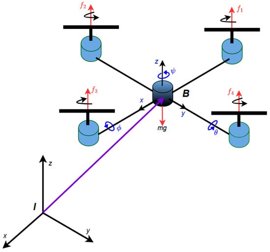
Figure 1.
Configuration of the quadrotor unmanned aerial vehicle (QUAV).
The translational dynamics of the QUAV are formulated with respect to two reference frames: the inertial reference frame (I), fixed relative to the Earth and serving as the global reference for position and orientation, and the body-fixed frame (B), which moves with the QUAV and is centered at its center of mass [31].
In a QUAV, thrust and torque control are produced by four fixed-pitch propellers arranged in two opposing pairs. Propellers 1 and 3 rotate clockwise, whereas propellers 2 and 4 rotate counterclockwise, counteracting the net torque to maintain stability. Control actions are achieved by modulating the rotational speeds of the propellers: altering the speed of opposite pairs governs pitch and roll; yaw control is obtained by introducing speed differentials between the clockwise and counterclockwise propellers; and vertical motion is regulated by simultaneously increasing or decreasing the speed of all four propellers, thereby adjusting the total thrust [31].
2.2. Mathematical Model of the QAUV
The dynamic behavior of QUAVs has been investigated in previous studies using various modeling approaches [32]. In this study, the dynamics are derived based on the Euler–Lagrange formulation, considering the QUAV as a rigid body moving in three-dimensional space under the action of a primary thrust force and three torque components, as illustrated in Figure 1 [31]. Accordingly, the generalized coordinates of the QUAV are defined as follows
where represents the position of the center of mass of the QUAV relative to a fixed inertial frame (translational coordinates) and denotes the Euler angles—yaw (), pitch (), and roll ()—which represent the orientation (rotational coordinates) of the QUAV [33].
By definition, the Lagrangian of the system is expressed as
where represents the global kinetic energy, is the potential energy, and the translational and rotational kinetic energy are defined as and , respectively. Consequently, Equation (2) can be rewritten as follows
where denotes the QUAV altitude, is the mass of the QUAV, is the acceleration due to gravity, and acts as the inertia matrix for the full-rotational kinetic energy of the QUAV, which is a function of the generalized coordinates .
The complete dynamic model of the QUAV is derived from the Euler–Lagrange equations, including the effect of external generalized forces, as follows
where denotes the generalized moments (i.e., yaw, pitch, and roll moments) and denotes the generalized translational force applied to the QUAV, which is generated by the control inputs.
The generalized translational force generated by the control inputs can be expressed as
where is the transformation matrix that defines the orientation of the QUAV relative to the fixed inertial frame , and is given by
where C and S denote the trigonometric functions and , respectively. And , with as the principal control input or principal force in the direction of the axis given by
where is the force produced by each motor (with ), is a constant and is the angular velocity of the motor.
The generalized moments on the yaw, pitch, and roll axes are defined as
where is the distance from the motors to the center of gravity.
Due to the absence of cross terms in the kinetic energy involving both translational and rotational generalized speeds. The Euler-Lagrange Equation (4) can be partitioned into the translations () and the rotational () dynamics as
By solving the translational and rotational Euler–Lagrange Equations (9) and (10), we obtain
where , , and the matrix contains the Coriolis terms due to the gyroscopic and centrifugal effects associated with the rotational generalized coordinate and is defined as
The elements of the matrix are defined as
And the inertia matrix is given by
To reduce the complexity of the QUAV dynamic model, we focus on flight paths that do not involve abrupt changes in position or orientation, as these are the primary scenarios of interest for the proposed control design [31]. Under this condition, the Euler angles approach zero (i.e., , , and ) for which
and
These relations correspond to the standard small-angle approximations, which are valid for hover and moderate maneuvers where roll, pitch, and yaw angles remain small. Such assumptions are widely used in QUAV modeling because they significantly reduce model complexity while retaining the essential nonlinear behavior. It is important to note, however, that when larger attitude deviations occur, the resulting mismatch can be interpreted as additional bounded uncertainties. Since the proposed BSMC–STO controller explicitly accounts for bounded disturbances and observer estimation errors in the stability analysis, the validity and robustness of the control framework are preserved beyond the strict range of these approximations. Nevertheless, it should be noted that extreme maneuvering conditions are beyond the scope of this work.
Therefore, using the above assumption and by substituting the generalized translational force , the generalized moments , the Coriolis matrix , and the inertia matrix in Equations (11) and (12). The complete mathematical model of the QUAV is as follows
where in the horizontal plane, the coordinates and define the position, while the vertical position is represented by the coordinate , is the yaw angle around axis, is the pitch angle around axis, and is the roll angle around axis. denotes the mass of the quadrotor, is the acceleration due to gravity, , , and are the moments of inertia along the , , and axes, respectively. and represent the trigonometric functions cosine and sine, respectively. The control inputs , , , and correspond to the total thrust and the angular moments (torques) around the yaw, pitch, and roll axes, respectively.
To facilitate both controller and observer design, the QUAV model is expressed in state-space form. The state vector is defined as , and the corresponding state-space representation is formulated as follows
where denotes the state vector, denotes thrust force and the yaw, pitch, and roll torques, respectively. represents the nonlinear system dynamics, which is defined as
And the parameters of the model are defined as follows
In the state-space representation of the QUAV, the functions for , denote time-dependent external disturbances acting on the QUAV system. These disturbances include aerodynamic effects, such as wind gusts and turbulence, as well as external forces arising from payload variations or environmental factors. The inclusion of these terms allows for a more realistic assessment of the controller’s robustness under non-ideal operating conditions [34].
It is important to note that, in practical scenarios, only a subset of the system states—typically position and orientation—can be measured directly. The remaining states, particularly the linear and angular velocities, must be estimated to enable full-state feedback control. Moreover, the presence of disturbances further increases the challenge of obtaining reliable state information [35]. To address this challenge, a robust observer capable of providing accurate state estimates is required. The design of a super-twisting observer (STO), a second-order sliding mode algorithm known for its finite-time convergence and strong robustness properties, is presented in the following section [36].
3. Super-Twisting Observer
The super-twisting observer (STO) is a second-order sliding mode algorithm widely recognized for its capability to achieve finite-time convergence of estimation errors. This property provides strong robustness against bounded disturbances and model uncertainties in dynamic systems. Compared to conventional sliding mode observers, the STO effectively mitigates chattering, yielding smoother and more accurate state estimates. Moreover, it does not require knowledge of the derivatives of the measured outputs, which simplifies its practical implementation in real-time applications [37]. In this section, the design methodology of the STO is presented.
Consider a second-order system described in state-space form as
where and denote the system states, denotes the control input, is a smooth nonlinear function representing the known system dynamics, and represents an unknown but bounded time-dependent disturbance.
The proposed STO for the system in Equation (22) is defined as
where denote the estimated states, and the correction signals , and are the output injection terms defined as
with denote the observer gains, selected to ensure the finite-time convergence of the estimation errors.
Defining the estimation errors as and , the error dynamics can be expressed as
with
Under the assumption that the system state remains bounded, there exists a constant such that the inequality
holds for any admissible values of , and , with . In accordance with the guidelines proposed in [37], the observer gains can be chosen as and .
Remark 1.
Equation (27) formalizes the boundedness assumption typically required in super-twisting observer design. Here,
does not indicate a specific numerical value but rather a known constant upper bound on the nonlinear function and external disturbances acting on the QUAV. This assumption is standard in sliding-mode observer theory [37], and is justified by the fact that the physical parameters of the QUAV and the external perturbations (e.g., wind gusts, payload variations) are bounded in practice. In this work, disturbances are explicitly modeled as bounded sinusoidal signals, which validates the existence of such an upper bound. The choice of observer gains ensures that the super-twisting correction terms dominate this bound, thereby enforcing finite-time convergence of the estimation errors.
Super-Twisting Observer for the QUAV
In this subsection, the STO methodology presented above is adapted to the nonlinear dynamics of the QUAV. The STO is used to estimate the velocity states in the presence of external disturbances. It is assumed that only the position coordinates and attitude angles are directly measurable. These correspond to the state variables , , , , , and in the mathematical model defined in Equation (19).
To facilitate the design of the STO, the QUAV model (as presented in Equation (19)) is reformulated to explicitly separate measurable and non-measurable states while incorporating the external disturbance terms. The corresponding adapted QUAV model is as follows
where denotes the measured states, denotes the unmeasurable states, corresponds to external disturbances, and encapsulates the system dynamics as
The STO for the QUAV is designed as
where are the observer states, and , are the correction signals defined as
with , and as the gain vectors of the STO, and the function is defined as
Defining the estimation errors as and , the dynamics of the errors can be expressed as
According to the result in [37], the convergence of the estimation error is guaranteed in finite time, provided that the nonlinear function is locally Lipschitz and the uncertainty term satisfies a uniform upper bound, i.e., , for some known vector constant . Accordingly, the observer gains are chosen as and , ensuring that the super-twisting correction terms dominate the uncertainties and enforce the finite-time convergence.
4. Backstepping Sliding Mode Control for a QUAV
The control of quadrotor unmanned aerial vehicles (QUAVs) is challenging due to their intrinsic nonlinearities, strong coupling between degrees of freedom, and sensitivity to external disturbances. In this context, the backstepping control approach provides a systematic framework for designing stabilizing control laws for nonlinear systems. This method recursively constructs virtual control inputs for a sequence of interconnected subsystems, ensuring the overall system stability through Lyapunov-based analysis [38].
Sliding mode control (SMC), on the other hand, is well known for its robustness against external disturbances and model uncertainties. When integrated into the backstepping framework, SMC enhances the resilience of the control architecture against disturbances, such as wind gusts and parametric uncertainties. The sliding mode component further contributes to maintaining stable flight and accurate trajectory tracking, even under adverse operating conditions [39].
The proposed backstepping sliding mode control (BSMC) strategy, thus, combines the advantages of both methods: the backstepping component provides structured controller development and guarantees convergence of system states, while the sliding mode component contributes robustness and improved tracking performance in uncertain and challenging conditions. Consequently, the BSMC approach offers a reliable and precise solution for QUAV control in realistic operational scenarios.
4.1. Design of the Backstepping-Sliding Mode Controller
The BSMC is designed based on the nonlinear state-space representation of the QUAV, which is decomposed into translational and rotational subsystems, as presented in Equation (18). Backstepping is applied to systematically construct stabilizing control laws for position and attitude dynamics, ensuring asymptotic convergence to the desired trajectory [40]. At each recursive step, a sliding mode component is incorporated to enhance robustness against external disturbances. The control inputs are computed from virtual control laws obtained through the backstepping framework and augmented with sliding mode terms to mitigate the effects of perturbations.
It should be noted that the linear and angular velocity states are not directly measurable and must therefore be estimated. To this end, the super-twisting observer (STO) introduced in Section 3 is employed to provide real-time estimates of these unmeasured states. The estimated velocities are subsequently used in the design of the backstepping sliding mode controller (BSMC), ensuring accurate full-state feedback and robustness against external disturbances.
The control design procedure is organized as follows.
Step 1. Define the position and orientation tracking errors.
To design the control law, the tracking errors between the desired and actual states of the QUAV are first defined. Let the desired trajectories for roll, pitch, yaw, and Cartesian positions () be denoted by , and , respectively. The corresponding tracking errors are then defined as
Step 2. Compute the time derivatives of the position and orientation tracking errors.
In this step, the time derivatives of the tracking errors for position and orientation are computed as the difference between the desired time-varying references and the corresponding velocity components of the QUAV state vector
In this study, the linear and angular velocity components of the QUAV state vector, corresponding to and are considered unmeasurable due to the practical limitations of standard onboard sensors. To overcome this, the STO, introduced in Section 3, is employed to reconstruct these unmeasurable velocity states. The STO is selected for its proven robustness against bounded disturbances and its ability to guarantee finite-time convergence of estimation errors under appropriate gain selection [37].
Once the STO reaches the sliding mode regime, the estimated velocities converge to the true values, i.e., for , where denotes the STO-based estimate of the jth velocity state. This convergence enables the substitution of the unmeasurable velocity components in Equation (35) with their observer-based estimates, preserving the accuracy of the control strategy. Accordingly, under the sliding regime, the time derivatives of the tracking errors can be expressed as
Step 3. Define the sliding surfaces.
In this step, the sliding surfaces are constructed based on the previously defined tracking errors. The sliding surfaces are defined as
where is a scalar gain that define the convergence rate of the sliding surface. The terms , , , , , and represent the sliding manifolds associated with the attitude and position errors of the QUAV. Driving these surfaces to zero ensures asymptotic convergence of both the tracking errors and their derivatives, thereby guaranteeing accurate trajectory tracking even in the presence of external disturbances.
Step 4. Define the sliding surface dynamics.
To ensure that the sliding manifolds are attractive—an essential condition for guaranteeing the stability of the proposed control scheme—their time derivatives are defined as
with ensuring finite-time convergence of the sliding variables.
Step 5. Define Lyapunov candidate functions.
The Lyapunov candidate functions are formulated to assess the stability of each subsystem associated with the position and orientation tracking errors. Each function combines the squared tracking error and the corresponding sliding surface, yielding positive definite expressions.
Step 6. Derive the control laws.
The control inputs for the position and orientation of the QUAV are formulated to ensure the asymptotic stability of the closed-loop system. The design procedure follows Lyapunov stability theory, ensuring that the time derivatives of the Lyapunov candidate functions remain strictly negative. To this end, the system dynamics and the sliding surface definitions are substituted into the Lyapunov derivatives. The control laws are then constructed to eliminate destabilizing terms while introducing stabilizing components that drive the system states toward the desired references. The resulting expressions are given by
4.2. Stability Analysis
In this subsection, the stability of the proposed BSMC–STO scheme is analyzed using Lyapunov theory. The analysis is conducted under explicitly stated assumptions on disturbances and estimation errors to ensure a clear and rigorous formulation.
Assumption 1.
The external disturbances affecting the translational and rotational dynamics of the quadrotor are bounded. That is, there exists a known constant such that
Assumption 2.
The estimation errors introduced by the super-twisting observer (STO) are bounded in finite time. Specifically, there exists a constant such that
Proposition 1.
(Uniform ultimate boundedness).
Under Assumptions 1 and 2, if the controller gains satisfy
Then the closed-loop roll subsystem of the quadrotor is uniformly ultimately bounded in the sense of Lyapunov. Moreover, if due to the finite-time convergence of the STO and , then the tracking errors and converge asymptotically to zero.
Proof.
Let the roll position tracking error be defined as
And the corresponding velocity error as
The sliding surface for the roll dynamics is selected as
Consider the Lyapunov candidate function
Taking the time derivative and using yields
From the roll dynamics of the QUAV, we have
where denotes the lumped perturbation satisfying Assumption 1.
The control input is designed as
where and are the state estimates from the super-twisting observer (STO).
Define the estimation error as
which satisfies Assumption 2. That is . Here, denotes an unknown but bounded constant representing the maximum estimation error of the STO under bounded disturbances. While its exact value is not required, the existence of such a bound is guaranteed by the finite-time convergence properties of the STO [37]. This assumption allows that the estimation error remains uniformly bounded during operation. Therefore, substituting (54)–(56) into (53) yields
Using
And Young’s inequality, for ,
We obtain
Therefore,
The terms involving can be rearranged and bounded using the known limits of disturbances and estimation errors as follows
Finally, combining all terms, the derivative of the Lyapunov function is bounded as
And if the controller gains satisfy
Then,
which guarantees that remains uniformly bounded, and the roll subsystem is stable in the sense of Lyapunov. Moreover, suppose the STO achieves its finite-time convergence so that and external disturbance vanished (), then both and converge asymptotically to zero.
Remark 2.
The above stability proof has been presented for the roll dynamics. The same reasoning applies to the pitch, yaw, and translational subsystems, thereby establishing the stability of the complete quadrotor dynamics under the proposed BSMC–STO framework.
The control design procedure outlined in this section establishes a robust framework for the trajectory tracking of the QUAV under external disturbances and partial state measurement conditions. By integrating the STO with the BSCM scheme, reliable velocity state estimation and disturbance rejection are achieved, ensuring the system’s stability and performance. The subsequent section presents simulation results that demonstrate the effectiveness of the proposed control strategy.
5. Results
This section presents a numerical evaluation of the proposed backstepping sliding mode control (BSMC) strategy integrated with a super-twisting observer (STO) for a QUAV. Three simulation scenarios are conducted to assess the performance and robustness of the control system under progressively challenging conditions. In the first case, the BSMC is tested under nominal conditions assuming full-state feedback, serving as a reference for ideal performance. The second case also considers nominal conditions but employs the STO to estimate the velocity states, thereby demonstrating the controller’s effectiveness under partial state measurement. The third case introduces bounded external disturbances affecting the translational and rotational dynamics of the QUAV, enabling the evaluation of the disturbance rejection capability of the observer-based control scheme. The goal is to verify whether the observer-based control maintains stability and precision when only partial state information is available and the system is subject to bounded external perturbations.
5.1. Simulation Setup
The proposed BSMC using an STO is tasked with following a three-dimensional helical trajectory designed to simultaneously challenge both the translational and rotational subsystems. This trajectory reflects agile and realistic aerial maneuvers typical in practical missions such as autonomous inspection and surveillance. By requiring concurrent horizontal and vertical displacements, it tests the controller’s capability to maintain stability, precision, and robustness in dynamic conditions. The desired trajectory of the angles and positions in the simulation study, it is chosen as .
The model and control algorithm are implemented using the Euler integration method with a fixed step size of 0.0001 s. All simulations are initialized from rest conditions, and the total simulation time is set to 15 s. External perturbations are modeled as bounded sinusoidal signals and introduced into the dynamics of the even-numbered states, which correspond to the linear and angular velocities of the QUAV. The physical parameters of the QUAV used in this study are presented in Table 1.

Table 1.
Parameters of the QUAV model [31].
The controller gains were chosen according to the stability conditions derived in (64), which ensure that , , and . These inequalities guarantee that the derivative of the Lyapunov function is negative semi-definite, thereby ensuring system stability. Within these admissible ranges, the specific values of the gains were further tuned through simulation experiments to balance robustness and transient performance.
Specifically, the controller parameters were set as , , . The parameter influences the convergence rate of the position error: higher values accelerate error decay but may increase control effort. The gain governs the damping of the sliding variable, improving steady-state smoothness while mitigating oscillations. The discontinuous gain provides robustness against bounded disturbances and estimation errors; larger values enhance disturbance rejection at the cost of increased chattering.
Finally, the observer gains and were chosen sufficiently large to dominate the expected disturbance bounds and ensure finite-time convergence of the estimation errors, while avoiding excessively high values that could cause peaking phenomena. The STO gains were set as , and . Both controller and observer gains remained consistent across all simulation cases to allow direct performance comparisons.
To quantify the tracking performance of the proposed controller, two classical error indices are used: the Integral Square Error (ISE) and the Integral Absolute Error (IAE), which measure the total deviation between the system output and the desired trajectory over time, thus enablingan objective comparison of control strategies under different conditions.
The ISE and IAE are defined as
where is the tracking error vector, denotes the desired trajectory vector, represents the actual system response vector, and is the total simulation time.
Lower values of ISE and IAE indicate improved tracking accuracy and controller performance. These metrics are employed to evaluate the impact of using estimated states from the observer versus measured states, and to quantify the controller’s robustness under external disturbances introduced in the simulations.
5.2. Case 1—BSMC with Full-State Feedback (Nominal Conditions)
In this baseline scenario, we assume complete state measurement availability, i.e., the BSMC receives direct feedback of both the linear and angular positions as well as their corresponding velocities, and no external perturbations are applied. Figure 2 and Figure 3 illustrate the trajectory tracking response and the 3D position path, respectively. As expected, the tracking error remains negligible throughout the simulation.
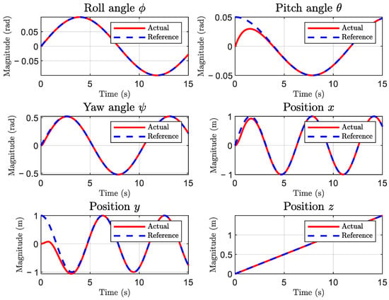
Figure 2.
Tracking response using BSMC under nominal conditions (case 1).
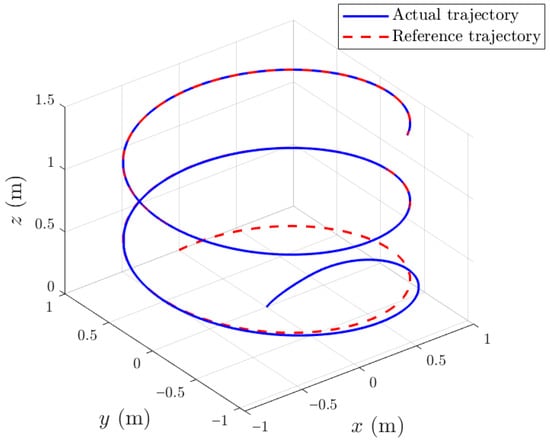
Figure 3.
Three-dimensional path of the QUAV using BSMC under nominal conditions (case 1).
Figure 4 presents the time evolution of the tracking errors for the roll, pitch, yaw, and translational states under full-state feedback control. Since all state variables are directly available for feedback and no disturbances are introduced, the errors remain negligible, confirming the near-optimal performance of the baseline BSMC controller.
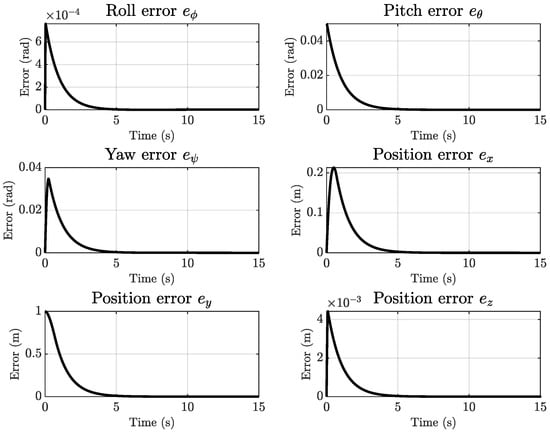
Figure 4.
Tracking errors of the QUAV under BSMC with full-state feedback (case 1).
Table 2 summarizes the tracking performance of each state variable in terms of the ISE and IAE indices. The results confirm that the baseline controller achieves near-ideal tracking accuracy. The ISE and IAE values for the roll, pitch, and yaw angles are on the order of or lower, indicating negligible orientation errors. Similarly, the translational states exhibit extremely small error levels, with the largest IAE occurring in the lateral displacement , which is still within an acceptable range given the helical trajectory. These results establish Case 1 as the performance benchmark, representing the upper bound against which observer-based and disturbance scenarios can be evaluated.

Table 2.
Tracking error indices (ISE and IAE) for Case 1—Full-state BSMC.
5.3. Case 2—BSMC with STO Under Nominal Conditions
In this scenario, the QUAV performs the same trajectory tracking task as in Case 1. However, only the position and angular variables are directly measured and available for feedback. The remaining state variables are estimated in real time using the super-twisting observer (STO) introduced in Section 3. No external disturbances are applied in this case. The STO is initialized with small deviations from the reference states to assess its transient convergence behavior.
Figure 5 illustrates the convergence of the state estimation provided by the STO, demonstrating rapid convergence with minimal transient deviation. Figure 6 depicts the tracking response of the BSMC controller utilizing the velocity states estimated by the STO.
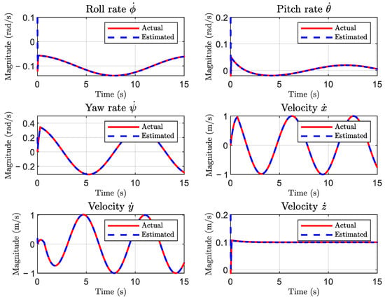
Figure 5.
STO estimation of velocity states under nominal conditions (case 2).
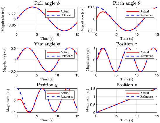
Figure 6.
Tracking response using BSMC with STO under nominal conditions (case 2).
Figure 7 shows the 3D trajectory of the QUAV under observer-based control without disturbances. The QUAV follows the reference path accurately in three-dimensional space, confirming the effectiveness of the STO in providing suitable estimates for the controller to maintain precise trajectory tracking.
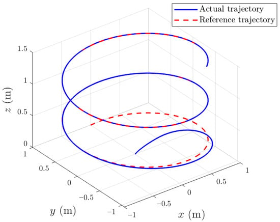
Figure 7.
Three-dimensional path of the QUAV using BSMC with STO under nominal conditions (case 2).
Figure 8 illustrates the tracking errors when the BSMC operates with velocity states estimated by the STO. Compared to the full-state case, only slight deviations are observed, and all errors remain bounded within acceptable limits. Table 3 quantifies this effect, showing that the performance degradation relative to Case 1 is marginal. For example, the roll angle IAE increases from 0.000751 to 0.0101, which is still two orders of magnitude smaller than the translational errors. Similarly, translational performance is essentially preserved, with variations less than 2%. These results confirm the effectiveness of the STO in reconstructing the unmeasured velocity state with high accuracy, thereby enabling the controller to achieve robust trajectory tracking. The slight increases in angular error are primarily due to transient estimation effects, while their magnitudes remain negligible for practical implementation.
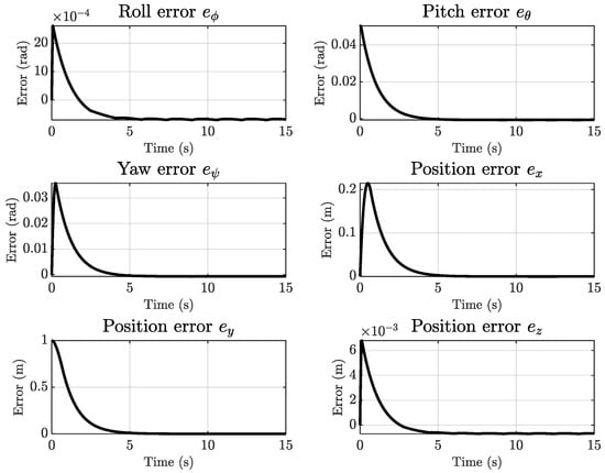
Figure 8.
Tracking errors of the QUAV under BSMC with STO-based state estimation (case 2).

Table 3.
Tracking error indices (ISE and IAE) for Case 2—BSMC with STO.
5.4. Case 3. BSMC with STO Under External Disturbances
In this scenario, the BSMC controller combined with STO-based state estimation is evaluated under the influence of bounded time-varying external disturbances. These perturbations are introduced into the even-numbered state equations, corresponding to the linear and angular velocity dynamics, and are modeled as sinusoidal signals. Such disturbances emulate realistic effects like wind gusts or environmental interactions. As in Case 2, the STO is used to estimate the unmeasured velocity states in real time, enabling the controller to operate effectively despite incomplete state information and the presence of dynamic perturbations.
Figure 9 illustrates the performance of the STO under external disturbances. Although the convergence rate is marginally slower compared to Case 2, the observer maintains an accurate estimation of the velocity components, thereby demonstrating robustness against time-varying perturbations.
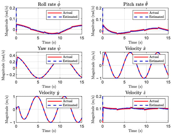
Figure 9.
STO estimation of velocity states under external perturbations (case 3).
Figure 10 shows the trajectory tracking performance of the system under external disturbances. Despite the disturbances, the controller manages to sustain stable and accurate tracking, with only a moderate increase in error compared to nominal conditions. Figure 11 depicts the 3D trajectory of the QUAV operating under observer-based control in the presence of external disturbances. Despite the sinusoidal perturbations applied to both translational and rotational dynamics, the QUAV successfully follows the desired spatial path with only bounded deviations.
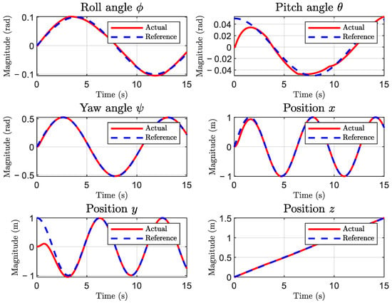
Figure 10.
Tracking response using BSMC with STO under external perturbations (case 3).

Figure 11.
Three-dimensional path of the QUAV using BSMC with STO under external perturbations (case 3).
Figure 12 presents the tracking errors when sinusoidal disturbances are injected into the velocity dynamics. Despite these perturbations, the proposed BSMC–STO framework maintains stable trajectory tracking, which highlights its robustness under dynamic uncertainties. The STO continues to provide sufficiently accurate velocity estimates, enabling the control law to counteract disturbances without compromising stability.
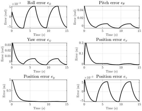
Figure 12.
Tracking errors of the QUAV under BSMC with STO in the presence of external disturbances (case 3).
The numerical results in Table 4 indicate that translational tracking performance is largely preserved. The IAE values for the - and -axes remain close to those obtained in the disturbance-free case, with only marginal variations. This outcome can be attributed to the inherent filtering capability of the STO, which attenuates high-frequency components of the injected perturbations and prevents their propagation through the translational dynamics.

Table 4.
Tracking error indices (ISE and IAE) for Case 3—BSMC with STO under external disturbances.
In contrast, the angular states exhibit higher sensitivity. The roll, pitch, and yaw errors increase relative to Case 2, reflecting the combined influence of estimation transients and the natural susceptibility of rotational dynamics to velocity-level disturbances. Nevertheless, the error magnitudes remain small in absolute terms and do not compromise the overall trajectory tracking quality.
5.5. Comparative Analysis
To establish a unified view of the control framework’s performance, a comparative evaluation is conducted across the three simulation cases. Figure 13 provides a direct comparison of tracking errors among the three simulation scenarios, while Table 5 summarizes the corresponding ISE and IAE indices.
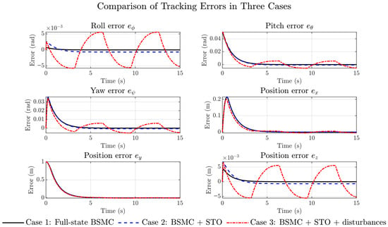
Figure 13.
Comparative tracking errors of the QUAV across the three control scenarios.

Table 5.
Summary of tracking error indices for all cases.
As expected, Case 1 exhibits near-ideal tracking, with negligible error levels across both translational and rotational states. This scenario confirms the intrinsic capability of the BSMC when full-state information is available and no perturbations are present. It therefore establishes a meaningful reference for subsequent evaluations.
In Case 2, the introduction of the STO to reconstruct velocity states results in only a marginal degradation of tracking accuracy. The error curves show small but bounded increases in angular deviations, while translational performance remains practically unchanged compared to Case 1. This highlights the STO’s effectiveness in providing reliable state estimates and validates the observer-based configuration as a realistic alternative for sensor-limited platforms.
The most insightful results emerge in Case 3, where bounded sinusoidal disturbances are introduced. The error plots reveal that translational tracking remains remarkably robust, with IAE variations less than 2% relative to Case 2. This resilience is explained by the STO’s filtering capability, which mitigates the propagation of disturbance components into the translational dynamics. In contrast, the angular states exhibit a more significant increase in error indices, reflecting their heightened sensitivity to velocity-level perturbations and transient estimation inaccuracies. Nevertheless, these deviations remain bounded and within limits that ensure the accuracy of trajectory tracking.
To further support the evaluation, a direct comparison is conducted between the proposed BSMC–STO scheme and the conventional super-twisting controller (STC) [17]. The STC is selected as the benchmark since it represents a widely adopted state-of-the-art nonlinear control strategy for underactuated aerial vehicles, recognized for its robustness and finite-time convergence properties. Importantly, this comparison is carried out under the same simulation conditions as Case 3, i.e., with bounded sinusoidal disturbances injected into the velocity dynamics. This ensures a fair assessment of both controllers under realistic operating conditions.
Figure 14 presents the time-domain responses of the attitude and position states. While both controllers achieve accurate steady-state tracking, the BSMC–STO converges faster to the reference signals, evidencing an improved transient performance without requiring gain retuning under disturbances.
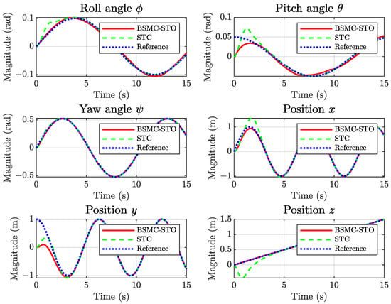
Figure 14.
Comparative tracking response of the QUAV with BSMC–STO and STC.
Figure 15 shows the three-dimensional trajectory tracking obtained with both controllers. The BSMC–STO and the STC converge to the reference helical path, with both maintaining comparable steady-state behavior. However, the BSMC–STO exhibits a smoother transient response, particularly in the vertical axis, reducing overshoot and deviations during initial maneuvers.

Figure 15.
Comparative 3D path of the QUAV with BSMC–STO and STC.
Figure 16 compares the corresponding tracking errors. In steady-state, the error levels of both schemes remain similar; nevertheless, the BSMC–STO consistently yields smaller deviations during transients, especially in angular dynamics. This indicates that the integration of the STO enhances disturbance attenuation and state estimation accuracy in the short term.
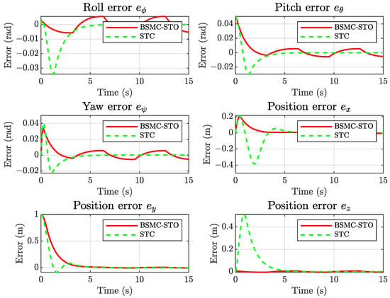
Figure 16.
Comparative tracking errors of the QUAV with BSMC–STO and STC.
Overall, the comparative analysis confirms that the BSMC–STO framework achieves robust performance. It maintains accurate trajectory tracking under sensor limitations and bounded external perturbations without requiring controller retuning. These results validate the proposed approach as a promising solution for QUAV operations in uncertain and dynamically challenging environments.
6. Discussion
The comparative results obtained across the three simulation scenarios (Table 2, Table 3, Table 4 and Table 5 and Figure 2, Figure 3, Figure 4, Figure 5, Figure 6, Figure 7, Figure 8, Figure 9, Figure 10, Figure 11, Figure 12, Figure 13, Figure 14, Figure 15 and Figure 16) demonstrate that the proposed BSMC–STO framework consistently ensures accurate trajectory tracking under nominal, observer-based, and disturbance-affected conditions. In Case 1, full-state feedback establishes the performance benchmark, showing near-zero tracking errors across all states. In Case 2, where velocity states are reconstructed through the STO, only marginal error increases are observed, confirming the observer’s effectiveness in replacing unavailable measurements without compromising overall performance. In Case 3, despite the injection of bounded sinusoidal disturbances, the framework maintains stable tracking with translational states largely unaffected and angular deviations remaining within practically acceptable bounds.
While the BSMC maintains stability and satisfactory tracking in the presence of bounded external disturbances, the observed performance degradation in rotational states suggests higher sensitivity of angular dynamics to velocity perturbations. This highlights the importance of carefully tuning BSMC-STO gains for both translational and rotational components to optimize robustness.
The additional comparison with the STC under identical disturbance conditions further reinforces the effectiveness of the proposed design. Both controllers achieve comparable steady-state accuracy; however, the BSMC–STO consistently delivers faster transient responses, reduced overshoot, and lower angular error magnitudes.
Compared with alternative designs that rely on explicit disturbance rejection schemes or adaptive controllers, the proposed BSMC–STO approach offers an appealing trade-off between simplicity and robustness. The framework achieves accurate trajectory tracking without the need for complex gain scheduling, auxiliary diagnostic modules, or controller retuning. This enhances its feasibility for real-world implementation, particularly in scenarios where sensing resources are constrained and environmental uncertainties are inevitable.
Nevertheless, the passive robustness exhibited by the proposed framework has inherent limitations. While the disturbance attenuation is effective against bounded and relatively smooth perturbations, stronger or rapidly varying disturbances may compromise the observer’s estimation accuracy and deteriorate angular tracking performance. Future research should therefore consider incorporating adaptive or active disturbance compensation mechanisms—such as disturbance observers or learning-based schemes—to complement the STO and enhance robustness under more demanding operating conditions.
7. Conclusions
This work proposed a robust nonlinear control strategy for QUAVs based on backstepping sliding mode control (BSMC) combined with a super-twisting observer (STO), aimed at scenarios with limited state measurements and matched external disturbances. The simulation results across three representative scenarios confirmed the effectiveness of the proposed scheme. Under nominal conditions with full-state feedback, the BSMC achieved near-perfect trajectory tracking. With velocity states reconstructed through the STO, the system preserved performance comparable to full-state feedback, confirming the observer’s reliability in replacing unavailable measurements. In the presence of external perturbations, the BSMC–STO scheme shown stability and bounded error behavior without requiring gain adjustments, evidencing strong robustness. Moreover, a comparative evaluation with the super-twisting controller (STC) under identical disturbance conditions highlighted the superior transient response of the proposed framework while maintaining similar steady-state accuracy. The results validate the potential of the BSMC–STO framework as a practical solution for QUAV control under sensing and environmental constraints. Future work will focus on extending the controller with active disturbance compensation mechanisms to enhance robustness under stronger and more dynamic perturbations.
Author Contributions
Conceptualization, V.B.-J. and J.G.-M.; methodology, V.B.-J., J.G.-M., R.F.E.-J., M.A.-M. and G.V.G.-R.; software, V.B.-J. and J.G.-M.; validation, V.B.-J., J.G.-M., M.A.-M., G.V.G.-R. and R.F.E.-J.; formal analysis, V.B.-J., R.F.E.-J., M.A.-M., G.V.G.-R. and J.G.-M.; investigation, V.B.-J., R.F.E.-J. and J.G.-M.; resources, V.B.-J., M.A.-M., G.V.G.-R. and J.G.-M.; data curation, V.B.-J., R.F.E.-J. and G.V.G.-R.; writing—original draft preparation, V.B.-J. and J.G.-M.; writing, V.B.-J., J.G.-M., R.F.E.-J., M.A.-M. and G.V.G.-R., review and editing, V.B.-J., J.G.-M., R.F.E.-J., M.A.-M. and G.V.G.-R.; visualization, V.B.-J.; supervision, V.B.-J., J.G.-M., M.A.-M. and G.V.G.-R.; project administration, V.B.-J. and R.F.E.-J. All authors have read and agreed to the published version of the manuscript.
Funding
This research received no external funding.
Data Availability Statement
No new data were created or analyzed in this study. Data sharing does not apply to this article.
Acknowledgments
We would like to thank the Mexican people who supported this research through the SECIHTI (Secretaria de Ciencia, Humanidades, Tecnología e Innovación— Secretary of Science, Humanities, Technology and Innovation), Mexico.
Conflicts of Interest
The authors declare no conflicts of interest.
Abbreviations
The following abbreviations are used in this manuscript:
| UAV | Unmanned Aerial Vehicle |
| QUAV | Quadrotor Unmanned Aerial Vehicle |
| BSMC | Backstepping Sliding Mode Controller |
| SMC | Sliding Mode Control |
| SMO | Sliding Mode Observer |
| STO | Super-Twisting Observer |
| VTOL | Vertical Takeoff and Landing |
References
- Telli, K.; Kraa, O.; Himeur, Y.; Ouamane, A.; Boumehraz, M.; Atalla, S.; Mansoor, W. A Comprehensive Review of Recent Research Trends on Unmanned Aerial Vehicles (UAVs). Systems 2023, 11, 400. [Google Scholar] [CrossRef]
- Idrissi, M.; Salami, M.; Annaz, F. A Review of Quadrotor Unmanned Aerial Vehicles: Applications, Architectural Design and Control Algorithms. J. Intell. Robot. Syst. 2022, 104, 1–33. [Google Scholar] [CrossRef]
- Ahmed, F.; Mohanta, J.C.; Keshari, A.; Yadav, P.S. Recent Advances in Unmanned Aerial Vehicles: A Review. Arab. J. Sci. Eng. 2022, 47, 7963–7984. [Google Scholar] [CrossRef]
- Lopez-Sanchez, I.; Moreno-Valenzuela, J. PID Control of Quadrotor UAVs: A Survey. Annu. Rev. Control 2023, 56, 100900. [Google Scholar] [CrossRef]
- Rinaldi, M.; Primatesta, S.; Guglieri, G. A Comparative Study for Control of Quadrotor UAVs. Appl. Sci. 2023, 13, 3464. [Google Scholar] [CrossRef]
- Ishibashi, Y.; Lichota, P.; Jacewicz, M.; Yuan, X.; Xu, J.; Li, S. Design and Simulation Verification of Model Predictive Attitude Control Based on Feedback Linearization for Quadrotor UAV. Appl. Sci. 2025, 15, 5218. [Google Scholar] [CrossRef]
- Jiang, B.; Li, B.; Zhou, W.; Lo, L.-Y.; Chen, C.-K.; Wen, C.-Y.; Chahl, J.; Wing, M. Neural Network Based Model Predictive Control for a Quadrotor UAV. Aerospace 2022, 9, 460. [Google Scholar] [CrossRef]
- Imran, I.H.; Stolkin, R.; Montazeri, A. Adaptive Control of Quadrotor Unmanned Aerial Vehicle with Time-Varying Uncertainties. IEEE Access 2023, 11, 19710–19724. [Google Scholar] [CrossRef]
- Labbadi, M.; Cherkaoui, M. Robust adaptive backstepping fast terminal sliding mode controller for uncertain quadrotor UAV. Aerosp. Sci. Technol. 2019, 93, 105306. [Google Scholar] [CrossRef]
- Thanh, H.L.N.N.N.; Huynh, T.T.; Vu, M.T.; Mung, N.X.; Phi, N.N.; Hong, S.K.; Vu, T.N.L. Quadcopter UAVs Extended States/Disturbance Observer-Based Nonlinear Robust Backstepping Control. Sensors 2022, 22, 5082. [Google Scholar] [CrossRef]
- Bao, C.; Guo, Y.; Luo, L.; Su, G. Design of a Fixed-Wing UAV Controller Based on Adaptive Backstepping Sliding Mode Control Method. IEEE Access 2021, 9, 157825–157841. [Google Scholar] [CrossRef]
- Borja-Jaimes, V.; Coronel-Escamilla, A.; Escobar-Jiménez, R.F.; Adam-Medina, M.; Guerrero-Ramírez, G.V.; Sánchez-Coronado, E.M.; García-Morales, J. Fractional-Order Sliding Mode Observer for Actuator Fault Estimation in a Quadrotor UAV. Mathematics 2024, 12, 1247. [Google Scholar] [CrossRef]
- Ahn, H.; Hu, M.; Chung, Y.; You, K. Sliding-Mode Control for Flight Stability of Quadrotor Drone Using Adaptive Super-Twisting Reaching Law. Drones 2023, 7, 522. [Google Scholar] [CrossRef]
- Chandra, A.; Lal, P.P.S. Higher Order Sliding Mode Controller for a Quadrotor UAV with a Suspended Load. IFAC-PapersOnLine 2022, 55, 610–615. [Google Scholar] [CrossRef]
- Zhao, Z.; Cao, D.; Yang, J.; Wang, H. High-Order Sliding Mode Observer-Based Trajectory Tracking Control for a Quadrotor UAV with Uncertain Dynamics. Nonlinear Dyn. 2020, 102, 2583–2596. [Google Scholar] [CrossRef]
- Cui, G.; Xu, H.; Chen, X.; Yu, J. Fixed-Time Distributed Adaptive Formation Control for Multiple QUAVs with Full-State Constraints. IEEE Trans. Aerosp. Electron. Syst. 2023, 59, 4192–4206. [Google Scholar] [CrossRef]
- Chalanga, A.; Kamal, S.; Fridman, L.M.; Bandyopadhyay, B.; Moreno, J.A. Implementation of Super-Twisting Control: Super-Twisting and Higher Order Sliding-Mode Observer-Based Approaches. IEEE Trans. Ind. Electron. 2016, 63, 3677–3685. [Google Scholar] [CrossRef]
- Chen, A.J.; Sun, M.J.; Wang, Z.H.; Feng, N.Z.; Shen, Y. Attitude Trajectory Tracking of Quadrotor UAV Using Super-Twisting Observer-Based Adaptive Controller. Proc. Inst. Mech. Eng. G 2021, 235, 1146–1157. [Google Scholar] [CrossRef]
- González, J.A.C.; Salas-Peña, O.; De León-Morales, J. Observer-Based Super Twisting Design: A Comparative Study on Quadrotor Altitude Control. ISA Trans. 2021, 109, 307–314. [Google Scholar] [CrossRef] [PubMed]
- Cui, L.; Hou, X.; Zuo, Z.; Yang, H. An adaptive fast super-twisting disturbance observer-based dual closed-loop attitude control with fixed-time convergence for UAV. J. Frankl. Inst. 2022, 359, 2514–2540. [Google Scholar] [CrossRef]
- Zhang, Y.; Fu, Y.; Han, Z.; Wang, J. Super-twisting algorithm backstepping adaptive terminal sliding-mode tracking control of quadrotor drones subjected to faults and disturbances. Drones 2025, 9, 82. [Google Scholar] [CrossRef]
- Liu, Z.; Zhang, O.; Gao, Y.; Zhao, Y.; Sun, Y.; Liu, J. Adaptive Neural Network-Based Fixed-Time Control for Trajectory Tracking of Robotic Systems. IEEE Trans. Circuits Syst. II Exp. Briefs 2023, 70, 241–245. [Google Scholar] [CrossRef]
- Liu, Z.; Liu, J.; Zhang, O.; Zhao, Y.; Chen, W.; Gao, Y. Adaptive Disturbance Observer-Based Fixed-Time Tracking Control for Uncertain Robotic Systems. IEEE Trans. Ind. Electron. 2024, 71, 14823–14831. [Google Scholar] [CrossRef]
- Liu, Z.; Zhao, Y.; Zhang, O.; Chen, W.; Wang, J.; Gao, Y. A Novel Faster Fixed-Time Adaptive Control for Robotic Systems With Input Saturation. IEEE Trans. Ind. Electron. 2024, 71, 5215–5223. [Google Scholar] [CrossRef]
- Maaruf, M.; Abubakar, A.N.; Gulzar, M.M. Adaptive Backstepping and Sliding Mode Control of a Quadrotor. J. Braz. Soc. Mech. Sci. Eng. 2024, 46, 1–15. [Google Scholar] [CrossRef]
- Shevidi, A.; Hashim, H.A. Adaptive Backstepping and Non-Singular Sliding Mode Control for Quadrotor UAVs with Unknown Time-Varying Uncertainties. arXiv 2024. Available online: https://arxiv.org/pdf/2407.07175 (accessed on 1 June 2025).
- Huang, S.; Huang, J.; Cai, Z.; Cui, H. Adaptive Backstepping Sliding Mode Control for Quadrotor UAV. Sci. Program. 2021, 2021, 3997648. [Google Scholar] [CrossRef]
- Li, J.; Wan, L.; Li, J.; Hou, K. Adaptive Backstepping Control of Quadrotor UAVs with Output Constraints and Input Saturation. Appl. Sci. 2023, 13, 8710. [Google Scholar] [CrossRef]
- Lhayani, M.; Abbou, A.; El Houm, Y.; Mahmoudi, H. Adaptive Nonsingular Fast Terminal Sliding Mode Control Based Finite-Time Disturbance Observer for a Quadrotor System. Proc. Inst. Mech. Eng. Part I J. Syst. Control Eng. 2025, 239, 761–789. [Google Scholar] [CrossRef]
- Ji, D.; Wang, R. Path Following of QAUV Using Attitude-Velocity Coupling Model. Ocean Eng. 2024, 294, 116885. [Google Scholar] [CrossRef]
- Hernández-Pérez, M.A.; Delgado-Reyes, G.; Borja-Jaimes, V.; Valdez-Martínez, J.S.; Cervantes-Bobadilla, M. An Adaptation of a Sliding Mode Classical Observer to a Fractional-Order Observer for Disturbance Reconstruction of a UAV Model: A Riemann–Liouville Fractional Calculus Approach. Mathematics 2023, 11, 4876. [Google Scholar] [CrossRef]
- Al-Mahturi, A.; Santoso, F.; Garratt, M.A.; Anavatti, S.G. Modeling and Control of a Quadrotor Unmanned Aerial Vehicle Using Type-2 Fuzzy Systems. In Unmanned Aerial Systems: Theoretical Foundation and Applications; Advances in Nonlinear Dynamics and Chaos (ANDC); Elsevier: Amsterdam, The Netherlands, 2021; pp. 25–46. [Google Scholar] [CrossRef]
- Castillo, P.; Dzul, A.; Lozano, R. Real-Time Stabilization and Tracking of a Four-Rotor Mini Rotorcraft. IEEE Trans. Control Syst. Technol. 2004, 12, 510–516. [Google Scholar] [CrossRef]
- Jin, P.; Ma, Q.; Xu, S. Dynamic Event-Triggered Robust Optimal Attitude Control of QUAV Using Reinforcement Learning. IEEE Trans. Aerosp. Electron. Syst. 2023, 59, 7798–7807. [Google Scholar] [CrossRef]
- Madani, T.; Benallegue, A. Sliding Mode Observer and Backstepping Control for a Quadrotor Unmanned Aerial Vehicles. In Proceedings of the American Control Conference, New York, NY, USA, 9–13 July 2007; pp. 5887–5892. [Google Scholar] [CrossRef]
- Salgado, I.; Chairez, I.; Moreno, J.; Fridman, L.; Poznyak, A. Generalized Super-Twisting Observer for Nonlinear Systems. IFAC Proc. Vol. 2011, 44, 14353–14358. [Google Scholar] [CrossRef]
- Fridman, L.; Shtessel, Y.; Edwards, C.; Yan, X.G. Higher-Order Sliding-Mode Observer for State Estimation and Input Reconstruction in Nonlinear Systems. Int. J. Robust Nonlinear Control 2008, 18, 399–412. [Google Scholar] [CrossRef]
- Nascimento, T.P.; Saska, M. Position and Attitude Control of Multi-Rotor Aerial Vehicles: A Survey. Annu. Rev. Control 2019, 48, 129–146. [Google Scholar] [CrossRef]
- Li, B.; Gong, W.; Yang, Y.; Xiao, B.; Ran, D. Appointed Fixed Time Observer-Based Sliding Mode Control for a Quadrotor UAV under External Disturbances. IEEE Trans. Aerosp. Electron. Syst. 2022, 58, 290–303. [Google Scholar] [CrossRef]
- Kapnopoulos, A.; Kazakidis, C.; Alexandridis, A. Quadrotor Trajectory Tracking Based on Backstepping Control and Radial Basis Function Neural Networks. Results Control Optim. 2024, 14, 100335. [Google Scholar] [CrossRef]
Disclaimer/Publisher’s Note: The statements, opinions and data contained in all publications are solely those of the individual author(s) and contributor(s) and not of MDPI and/or the editor(s). MDPI and/or the editor(s) disclaim responsibility for any injury to people or property resulting from any ideas, methods, instructions or products referred to in the content. |
© 2025 by the authors. Licensee MDPI, Basel, Switzerland. This article is an open access article distributed under the terms and conditions of the Creative Commons Attribution (CC BY) license (https://creativecommons.org/licenses/by/4.0/).