Abstract
Vibration control is a critical aspect of engineering, particularly in structures and mechanical systems where excessive oscillations can lead to fatigue, noise, or failure. Vibration suppression is essential in aerospace, automotive, civil, and industrial applications to enhance performance and longevity of systems. Piezoelectric shunt circuits (PSCs) offer a passive or semi-active approach to damping vibrations by leveraging the electromechanical properties of piezoelectric materials. Traditional passive damping methods, such as viscoelastic materials, are effective but lack adaptability. Active control systems, while tunable, require external power and complex electronics, increasing cost and weight. Piezoelectric shunt circuits provide a middle ground, utilizing piezoelectric transducers bonded to a structure and connected to an electrical circuit to dissipate vibrational energy as heat or store it electrically. This review synthesizes the fundamental mechanisms, circuit designs, and practical applications of this technology. It also presents the modeling of lumped and distributed parameter systems coupled with PSCs. It complements the recent reviews and primarily focuses on the period from 2019 to date in addition to the earlier seminal works on the subject. It explores the principles, configurations, advantages, and limitations of piezoelectric shunt circuits for vibration control, alongside recent advancements and potential future developments. It sheds light on the research gaps in the literature that future work may tackle.
1. Introduction
Vibration suppression is a critical aspect in various engineering applications, aimed at improving performance, reducing noise, and extending the lifespan of structures and machines. The design of effective vibration absorbers plays a critical role in ensuring the optimal performance and longevity of equipment, regardless of whether the systems involved are on the microscale, such as MEMS, or larger-scale industrial applications. Poorly designed vibration absorbers can lead to a range of undesirable consequences, from increased noise pollution to poor performance and, eventually, system failure. Before a detailed discussion of the piezoelectric shunts is presented, the reader is referred to relatively new vibration suppression techniques. In the past two decades, the inerter has garnered much attention owing to its unique mechanical characteristics. As a substitution of the capacitance element based on the electrical-mechanical analogy, the inerter has outstanding advantages [1]. Inerter is a new element in the vibration isolation system. It can improve the vibration suppression ability of the system effectively. In addition, inerter is lightweight and has two free terminals compared with mass. These advantages make the application fields of inerter wider than those of mass. Vibration monitoring through smart controllers and a specific class of shell dampers. In particular, the reader can refer to the use of a smart controller for the assessment of drill string bottom-part vibrations and shock loads, Landar et al. [2]. They used Smart 4 controller, which is equipped with a three-axis accelerometer and a gyroscope, paired with a lithium thionyl chloride battery. Velychkovych et al. [3] presented friction dampers based on the effects of dry friction because of their simple design, low manufacturing and maintenance costs, and high efficiency under heavy loads. This study proposed a new damper design based on an open shell with a deformable filler, with the shell cut along a cylindrical helical line. Shatskyi and Velychkovych [4] presented a new dry friction shell shock absorber design. The shock absorber contains two spring sections and a friction module with an open shell and an elastic filler; at the same time, the spring sections and the friction module work in parallel. The proposed device demonstrates good damping characteristics, is capable of operating under high operating loads, and at the same time has compact transverse dimensions. With a nonmonotonic loading of such a shock absorber, due to the contact interaction of the filler with an open shell, part of the energy that is supplied to the system will be dissipated.
Piezoelectric shunt circuit absorbers have been used as a passive vibration absorber as an alternative to the traditional tuned mass dampers (TMDs), where they have the advantage due to their ease of tuning, straightforward implementation, and minimal added weight, making them a preferred choice for many applications [5,6]. Piezoelectric materials, known for their ability to convert mechanical energy into electrical energy and vice versa, have been extensively utilized for this purpose. Piezoelectric shunt circuits offer an effective method by dissipating vibrational energy through conversion into electrical energy, which is then dissipated in the circuit. Piezoelectric shunt circuits operate on the principle of the direct piezoelectric effect, where mechanical vibration induces an electrical charge in the piezoelectric material. This electrical energy is then routed into a shunt circuit, where it is dissipated, typically as heat, thereby reducing the mechanical vibration. The effectiveness of the shunt circuit depends on its ability to match the impedance of the piezoelectric transducer and the host structure, ensuring efficient energy transfer. Modeling involves understanding the electromechanical coupling, often using finite element methods, and tuning the circuit parameters to achieve desired damping. Common types of shunt circuits include resistive (R), resonant (RL), and more complex configurations involving capacitors and negative capacitance, each tailored to specific vibration control needs.
Due to their remarkable characteristics and diverse uses, piezoelectric materials have drawn a lot of attention in the fields of materials science and engineering. There are two types of piezoelectric effect: the direct effect, where the material converts the mechanical strain into an electrical charge, and the reverse effect, where the material converts an applied electrical potential into a mechanical strain [7]. The direct effect is usually used when the piezoelectric material functions as a sensor, whereas the reverse effect is commonly used when the piezoelectric material functions as an actuator. The piezoelectric fabulous features were exploited to develop active control systems that can be utilized in a variety of industries, including healthcare [8,9], energy harvesting [10], and sensor technologies [11]. Among the numerous applications of piezoelectric materials, their usage in vibration damping systems has emerged as a potential topic of research. Forward [12] suggested the use of a piezoelectric patch that is connected to electrical elements to transform the structure’s vibrational energy into electrical energy. The mechanical–electrical analogy can be used to explain how the mechanical damping system and the electric circuit are related. The structure’s mass, stiffness, damping, and force excitation are equivalent to the electrical circuit’s inductance, capacitance, resistance, and voltage, respectively. Researchers classified piezoelectric shunt circuits into three categories depending on their control methods: passive, active, semi-passive, or semi-active. The electrical elements in the shunt circuits, as well as the existence of any external power source, determine which type is used, with each having unique benefits and limitations.
The passive technique relies on the inherent ability of the piezoelectric material to absorb vibrational energy, resulting in passive energy dissipation without any external power source. On the other hand, active methods utilize sensors and actuators to achieve vibration sensing and activation to suppress vibration in real time [13]. An active control system usually requires powerful power amplifiers and high-performance digital signal processors, which are inappropriate for space applications, to drive actuators. Despite being simpler to construct than active control systems, passive control methods are less resistant to system disturbances [14]. Therefore, the interest in semi-active and semi-passive control systems has increased because of their potential to successfully offer vibration damping using piezoelectric materials. These systems combine the benefits of adaptability and energy efficiency to provide an adaptable way of reducing vibrations in various applications. It is essential to keep in mind that while active control systems can be used to limit low-frequency vibrations, passive shunt circuits can be highly effective at damping high-frequency excitations. Additionally, semi-passive and semi-active techniques are necessary for good control over wide frequency bands, where the hybrid methods combine the best attributes from active and passive approaches [15]. Piezoelectric shunt circuits have been implemented in aerospace applications, including the damping of wing flutter in aircraft and satellite panels; automotive in reducing noise and vibration in chassis or engine mounts; civil engineering in stabilizing bridges and buildings against wind or seismic loads; and precision machinery in suppressing micro-vibrations in optical systems and manufacturing equipment.
This review provides a comprehensive overview of the current state of the art on vibration suppression using piezoelectric shunt circuits, covering their fundamentals, types, applications, recent developments, and future directions. It complements and builds on the recent reviews of Gripp and Rade [5] and Marakakis et al. [6]. The paper is structured as follows: Section 2 presents the types, applications, and recent development of shunt circuits that detail various types, their advantages, and limitations; applications in structural vibration control, noise reduction, and specific industrial contexts; and advances in semi-active and active systems, multi-mode circuits, energy harvesting, and advanced control techniques. Section 3 presents the mathematical models for the coupled response of discrete and distributed parameter systems attached with piezoelectric shunt circuits. Section 4 presents conclusions that highlight advantages, limitations, challenges, and future directions.
2. Types, Applications, and Recent Advances of Piezoelectric Shunt Circuits
Although active piezoelectric damping systems have drawn significant attention, the utilization of piezoelectric shunt circuits in vibration suppression offers important benefits in some applications. Starting with the classical approach, passive control methods provide many benefits, such as the fact that they function without the need for external power or any active control systems, which simplifies the implementation and reduces energy consumption, playing a significant role in drawing attention to it and making it preferable to active control systems.
2.1. Single-Mode Resistive (R), Resonant (RL), and (RLC) Circuits
Hagood and Flotow [16] proposed the concept of dissipating mechanical energy by a piezoelectric transducer that is shunted to a passive electrical circuit where the piezoelectric transducer is shunted to a resistor. The piezoelectric transducer behaves as a viscoelastic damper in this case. Where the mechanical energy that is converted to electrical energy will be dissipated as heat from the resistor, in most applications, the resistive shunt is the least considered due to its poor performance. In another case, they implemented a series resistor–inductor circuit (resonant) in the system. This configuration can create an electrical frequency and an impedance in the electric circuit, so it can be tuned to equal the structure’s natural frequency for a single mode, thus damping the highest vibration amplitude by inducing antiresonance at the natural frequency and minimizing the capacitance of the piezoelectric patch. Moreover, Hagood and Von’s approach came with a limitation: damping a low-frequency resonance requires a low electrical resonance, which requires large inductors. The difference between the resistive and resonant circuits was further investigated by Thomas et al. [17]. They found out that while the RL-shunt is the most effective, the R-shunt works well for structures with minimal damping. It is simpler to set up and adjust, making it a viable option. And the most important parameter that controls the performance of the shunt, besides the tuning, is the electromechanical coupling factor that depends on the piezoelectric patch’s ability to convert mechanical to electrical energy.
Countering the large inductance problem, Yamada [18] demonstrated a passive technique using a multi-layered piezoelectric transducer for suppressing vibration in flexible structures. The purpose of utilizing a multi-layered piezoelectric element was to improve its capacitance, removing the necessity for a high inductance value in the circuit. Another solution for the large inductance problem was using a synthetic inductor, that by using operational amplifiers a large value of inductance can be emulated with lower energy consumption. The solutions for the large inductance were not confined solely to the piezoelectric patch aspect. Other researchers suggested improving the inductor’s internal design (magnetic core) [19]. Different connections of RL circuits (in series and parallel) were investigated in [20], demonstrating a great damping performance by both configurations and especially by the proposed parallel connection that was invented by Wu [21]. Other researchers tried to evaluate the performance of RL circuits under different circumstances and how the tuning is going to be affected. Darleux et al. [22] presented a resonant shunt that can maintain its tuning under different temperatures by using a variable inductor that has a magnetic core that is influenced by the variation in temperature. Pernod [23] presented a resonant circuit that damps the vibration of a cantilever beam under flow-induced vibrations in a water tunnel. The ability to work under different circumstances made the utilization of RL circuits in damping vibration presented in many applications, such as rotor and machine blades [24,25], and aircraft structures [26,27].
While RL shunt circuits have shown promise in improving vibration damping, their effectiveness is highly dependent on selecting the appropriate electrical parameters: resistance (R) and inductance (L). To maximize energy dissipation, aligning the electrical and mechanical resonance frequencies is a must. Many researchers worked on the optimum tuning of the shunt circuit [28]. The first two optimization techniques that were proposed for tuning the circuit were presented by Hagood and Flotow [16]. The first optimization approach is the transfer function optimization method that works based on optimizing circuit parameters to eliminate or minimize peaks in the transfer function at resonance frequencies, hence reducing the system’s response to vibrations [29,30,31]. The other method is the pole placement technique. This method focuses on tuning electrical characteristics so that the system poles are as far to the left as possible on the complex plane. Shifting these poles improves the system’s stability and damping properties, resulting in better attenuation [32,33]. Matveenko et al. [34] proposed an approach for selecting the circuit parameters based on a mathematical formulation of the real and imaginary parts of the complex eigenfrequencies by solving for the natural vibration problem. Toftekær et al. [35] demonstrated a method for resistor and inductor tuning for shunt circuits using commercial finite element software ANSYS 18.0. The tuning method is based on using the finite element software to find the short circuit and open circuit natural frequencies of the given structure to find the optimal resistor and inductor values for vibration attenuation. In order to maximize the time-averaged electric power dissipation in the shunt resistor and optimize a shunt piezoelectric vibration absorber, Gardonio [36] introduced an online extremum seeking tuning technique. The method sequentially adjusts the shunt resistance and inductance using a two-path gradient search algorithm.
Those approaches stand out from others that use optimization algorithms for tuning circuit parameters, such as particle swarm optimization [37,38], ant colony optimization [39], and other tuning techniques [40,41]. The optimization in piezoelectric shunt circuits is not exclusive to electrical parameters. The dimensions and the position of the piezoelectric patch play a huge role in the performance of the system by affecting the EMCF and the capacitance of the piezoelectric patch [42]. They suggested adjusting the arrangement and configuration of shunt piezoelectric patches to enhance vibration damping by improving the modal electromechanical coupling factor (MEMCF). The appropriate patch thickness is dependent upon the Young’s modulus ratio, and its placement must correspond with regions of maximal mode shape slope difference. Symmetric configurations featuring two patches demonstrated greater efficacy than asymmetric arrangements.
2.2. Multi-Mode Resonant (RL) Circuits
In most life applications, systems are going to have multiple modes; damping multiple modes of vibration was a concerning matter in the field of piezoelectric shunt circuits. Hollkamp [43] proposed an approach for suppressing multiple modes using a single piezoelectric element as shown in Figure 1. Additional L-R-C circuit branches are coupled in parallel to an RL branch, this work is considered to be the first in presenting a capacitor in a shunt circuit and also having multiple branches. The number of RLC branches equals the number of modes chosen to be damped. However, it initially lacked a controlled method for tuning each branch separately. Subsequently, researchers tackled this challenge by proposing other circuit configurations to control the branches.
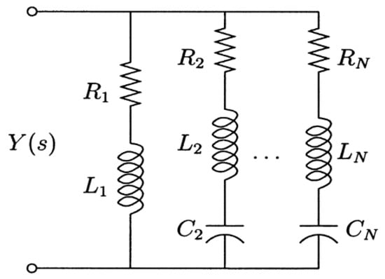
Figure 1.
The electric circuit proposed by Holkamp [43].
Wu [42,44] developed a multi-mode shunt that utilizes a current-blocking circuit. The electrical impedance of the LC anti-resonant circuits is designed to reach infinity and act as an open circuit at other branch frequencies, while the targeted branch that matches the resonance frequency of the structure operates and damps the vibration. On the other hand, Behrens et al. [45,46] proposed using “current-flowing” branches in the shunt circuit, as shown in Figure 2. The function of the current-blocking shunt and the current-flowing shunt is similar. The current-flowing shunt permits the current to flow rather than stopping it at the natural frequency. This method is better than “current blocking” because the latter requires an equal number of inductors for each mode. A distributed array of piezoelectric transducers connected with RL circuits on a cantilever beam is represented mathematically by Dell Isola et al. [47] each patch is adjusted to dampen a specific mode.
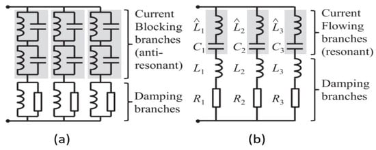
Figure 2.
(a) Current-blocking circuit and (b) current-flowing circuit, [45,46].
In order to minimize vibrational energy, Fleming and Moheimani [48] proposed a technique for optimizing piezoelectric transducer (PZT) multimode shunt circuits by minimizing the H2-norm of the damped system to obtain ideal resistance values. They achieved considerable mode reduction with reductions of 22 dB and 18 dB in the second and third structural modes, respectively. A neuro-fuzzy controller is proposed by Tairidis [49] in order to improve the performance of multi-modal shunt damping using piezoelectric patches. The objective of the neuro-fuzzy control system was the activation of the suitable shunt circuit at the required frequency. Raze et al. [50] proposed a tuning approach for a simplified current-blocking shunt circuit, and they introduced a two-port network with an electro-mechanical structure called a fictitious shunt branch. Its objective is to tune the electrical elements of the shunt circuit without involving any optimization algorithm. Raze et al. [51] developed a novel sequential tuning method. Based on the effective characteristics of the piezoelectric system around resonance, the shunt impedance’s characteristics, such as electrical damping ratios and resonance frequencies, were derived. Ribeiro and Lima [52] proposed the use of passive control to improve aeroelastic stability in lightweight composite structures. The authors proposed using multimodal shunt piezoceramics in parallel topologies, as shown in Figure 3, to increase the supersonic flutter boundary of composite panels.
Figure 3.
(a) Composite plate FE model with PZT element and (b) resonant circuit in parallel topology for shunt damping of two modes [52].
2.3. Negative Capacitance Shunt Circuits
Piezoelectric materials have intrinsic capacitance due to their dielectric characteristics. In a fundamental electrical equivalent model, a piezoelectric patch operates similarly to a capacitor. In addition to the piezoelectric patch’s intrinsic capacitance, an external capacitor can be added to the shunt circuit to change its resonance properties and improve performance in vibration control, while the resonant RL circuit operates similarly to the classical dynamic vibration absorber. Using capacitive circuits changes the stiffness of the piezoelectric element [53,54]. The addition of an external capacitor modifies the circuit’s total impedance, which can change the resonance frequency and increase the system’s damping capabilities. Park et al. [55] and Park and Inman [56] suggested an upgraded shunt circuit consisting of a capacitor C and an RL branch in parallel (RL-C parallel circuit), which allows the ideal value of the inductance L to be reduced for tuning the circuit with a structure that have a low natural frequency. Caruso [40] investigated the former RL-C circuit by comparing it with the RL series and RL parallel, although the RL-C circuit allows for reducing the inductance value, the results indicate that it does not perform as good as the RL series circuit. Berardengo et al. [57] introduced an (LRLC) circuit, as shown in Figure 4, that has two inductors, one capacitance, and one resistance, resulting in two resonances. The presence of supplementary resonance enhances performance and robustness. According to the results of the numerical simulation, the LRLC shunt had better attenuation values than the LR shunt and a lower amplitude in the FRF, as shown in Figure 5.
Figure 4.
Circuit diagram of the parallel LR shunt [57].
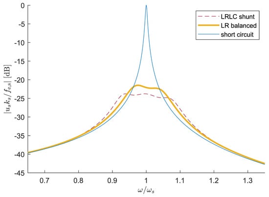
Figure 5.
Frequency response plot for the LRLC shunt [57].
Moreover, the role and shape of the capacitors were modified by introducing the negative capacitance in piezoelectric shunt circuits. Negative capacitors are different than the ordinary capacitors, where the former are not considered as a passive component because they contain operational amplifiers. The negative capacitor can increase the electromechanical coupling factor and also increase the broadband of the absorber by canceling the reactive impedance and the inherent capacitance of the piezoelectric patch. Park and Park [58] proposed a shunt circuit that utilizes piezoceramic patches to attenuate multi-mode vibration amplitudes. The piezoelectric patches are connected in series and parallel to resistor-negative capacitor branch circuits, as shown in Figure 6. The theoretical analysis provides evidence that this system is capable of significantly minimizing the amplitudes of multiple-mode vibrations throughout the entire frequency range of the structure.
Figure 6.
A schematic of the shunted piezo/beam system [58].
The implementation of a negative capacitance is investigated by Behrens et al. [45]. They demonstrated that the shunt negative capacitance controller effectively attenuates multiple vibration modes. It is less sensitive to environmental changes, easier to implement, and functions as a broad-spectrum vibration absorber. They showed the effectiveness of this method in damping the first six vibration modes. Billon et al. [59] presented a piezoelectric suspension that is connected to an RCN shunt circuit. Negative capacitance shunting offers potential for broadband performance but is limited by the operational amplifiers’ lower voltage capacity compared to the higher driving voltages of piezoelectric transducers. To address this, Pohl [60] introduced a specialized amplification circuit designed for higher voltage applications. Also, to solve the problem of capacitance mistuning, they introduced an adaptive negative capacitor that can be electronically tuned to the value of the inherent capacitance of the patch to the electromechanical coupling between the structure and the circuit. Berardengo et al. [61] examined piezoelectric shunts with negative capacitance (NC). In order to balance attenuation and OP-AMP efficiency, they investigated lowering operational amplifier (OP-AMP) demands, improving circuit characteristics, comparing configurations, and offering recommendations for developing NC systems. Wang et al. [62] suggested enhancing vibration suppression and energy harvesting in piezoelectric shunt circuits by utilizing negative capacitance (NC). A self-sustaining system is made possible by the negative capacitor, which enhances suppression while maintaining positive net power.
2.4. Switching Circuits
In order to control energy flow in piezoelectric shunt circuits, state switching involves alternating a piezoelectric actuator between open-circuit (high stiffness) and short-circuit (low stiffness). Up to four switching events are permitted every cycle by the switching sequence, which is controlled by a heuristic control law. The circuit switches, usually from open to short circuit by connecting an inductor or resistor, at maximum stretch (peak strain). The charge is redirected by this switch, oscillating and reversing its path. The circuit reopens after half a cycle, leaving the piezoelectric patch with an opposing charge that opposes its motion. This helps manage deflection, store energy, and release it when required. Piezoelectric actuators’ ability to alter mechanical stiffness between open- and closed-circuit states, which improves electromechanical coupling, is a key feature. Because of its self-adaptive broadband behavior, it is less sensitive to changes in the excitation frequency and electric elements than passive resonant shunting, Wu et al. [63].
State-switching was initially employed by Larson [64] to develop an acoustic driver that operated across a wide frequency range. A similar method called synchronized switched damping (SSDS) was later used by Richard et al. [65,66], who operated an actuator connected to a resistor in a high-stiffness state for the majority of the vibration cycle and then immediately switched to a low-stiffness state to release energy. Other researchers proposed connecting other electrical components in series with the state switch. Clark [67,68] developed a semi-active control method for mechanical systems that makes use of state-switched piezoelectric actuators (SSD). To store and release energy as needed, the piezoelectric actuator is switched between an open-circuit, short-circuit, or resistive-circuit state. Wu et al. [63] introduced a new semi-active piezoelectric damping technique using networking synchronized switch damping (SSD) to reduce vibration in integrally bladed disks (blisks). This method links piezoelectric materials in a network across blade sectors, allowing energy dissipation and redistribution through fewer SSD circuits, lowering system complexity in contrast to a typical SSD. Wu et al. [69] presented a linearization technique for synchronized switch damping (SSD) that reduces the intricate nonlinear behavior of SSD to stiffness and viscous damping coefficients that vary with frequency. The utilization of SSD circuits in several applications was further investigated by Liu et al. [70].
Another method for synchronized switch circuits that use an additional inductor (SSDI) was proposed in [71,72]. Rather than discharging the piezoelectric stored energy during a short circuit, the patches are coupled to an inductor, which allows the voltage to be inverted before being released to open circuit. And by that, the damping mechanism is improved by optimizing the voltage amplitude to be 90 degrees out of phase with the motion.
A control method that controls the modal energy rate was proposed by Corr and Clark [73] for the (SSDI). This method implies that the energy is always dissipated during vibration by operating the switch at the appropriate times to keep the modal energy change rate below zero. In order to control blade vibration, Ji et al. [74] introduced a semi-active multi-mode vibration control system. In multi-modal applications, this method reduces excessive switching, enhancing vibration control and energy conversion efficiency. The self-tuning (SSDI) technique, which was presented by Kelley and Kauffman [75], adjusts the ideal switch time for vibration reduction without requiring system parameter knowledge. In contrast to traditional SSDI, which only improves switching at resonance, this adaptive method matches resonance performance while improving off-resonance vibration control by using a gradient-based search to find the optimal switch timing depending on phase and system dynamics. Yu et al. [76] suggested an interconnected SSDI technique that, under ideal phase conditions, reduces resonance peaks by more than 30% by establishing an energy transfer channel between piezoelectric patches. Using an improved SSDI technique with a switching algorithm based on displacement thresholds.
Petite et al. [77] proposed a different version of synchronized switching circuits. They developed a method called synchronized switch damping voltage (SSDV) to improve vibration damping in lightweight structures, especially when there is a weak electromechanical link. In contrast to SSDS and SSDI, which depend on the electromechanical coupling coefficient, SSDV enhances damping performance by compensating for poor coupling by raising the piezoelectric voltage [78,79]. The SSDV can enhance control performance by amplifying the inverted voltage through the use of a voltage source connected in series with the inductor and connected to the shunting branch. However, using a constant voltage source caused a stability problem. To increase SSDV stability, Badel et al. [80] suggested an improved SSDV technique where the voltage is proportional to the vibration amplitude. To overcome this limitation, further adaptive SSDV strategies are also proposed [81]. Also, to overcome the drawbacks of SSDI and SSDV, which necessitate frequent readjustments of control parameters, Zheng et al. [82] presented a self-powered SSDV (synchronized switch damping on voltage source) circuit for vibration control of motorized spindles by using two voltage sources. Synchronized switch damping on Voltage (SSDV) had been implemented to solve the issue of dependence on the quality factor of the SSDI; however, it introduced a new issue, which is the need for a constant voltage source.
A technique known as synchronized switch damping on negative capacitance (SSD-NC) was introduced by Ji et al. [83] to substitute a negative capacitor for the voltage source. This results in decreasing the inherent capacitance of the piezoelectric transducer, and thus increasing the electromechanical coupling factor, which in turn causes the damping to increase [84]. Tang et al. [85] presented a self-sensing SSDNC circuit that eliminates the requirement for additional sensors and controllers by controlling vibration in cantilever beams with just a basic analog circuit. According to theoretical and experimental assessments, running the OP-AMP in saturation as opposed to the linear area greatly improves stability and damping performance, resulting in ideal attenuation that is less sensitive to changes, Ji et al. [86] created a novel technique to improve vibration control performance by creating unsymmetrical bipolar voltage utilizing an SSDNC shunt circuit. This design simplifies the SSDNC set up in comparison to conventional unsymmetrical SSDV circuits by adding a diode and resistance to the negative capacitance circuit. The study offers a general equation for the switching voltage on the piezoelectric actuator and analyzes stability using offset resistance and negative capacitance. Simulation and experiment results are presented to validate the proposed technique. Figure 7 shows that it can achieve better vibration suppression performance compared to traditional control systems.
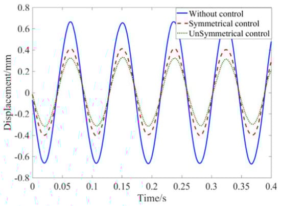
Figure 7.
Time domain plots of the displacement [86].
2.5. Quadratic and Cubic Nonlinear Shunt Circuits
The introduction of quadratic and cubic nonlinear electrical components in piezoelectric shunt circuits has demonstrated great potential for improving vibration suppression capabilities. Unlike linear elements, which provide damping across a narrow frequency range, quadratic and cubic nonlinearities allow for a more flexible and adaptable response to changing vibration intensities and frequencies. The first introduction of quadratic and cubic nonlinear electrical elements into piezoelectric shunt circuits was performed by Agnes and Inman [87]. The proposed model can expand the bandwidth of a piezoelectric absorber, but it also generates undesired nonlinear phenomena, including quasiperiodic and chaotic motions. Soltani and Kerschen [88] investigated the impacts of a nonlinear piezoelectric tuned vibration absorber based on the similarity principle that is intended to reduce the vibrations of a nonlinear primary system. This principle, which particularly requires that the order of the absorber’s nonlinearity equal that of the main system, guarantees that the absorber’s dynamic behavior mirrors that of the primary system. These properties work together to transfer energy efficiently, which improves vibration attenuation. Lossouarn et al. [89] presented the first fully passive nonlinear piezoelectric tuned vibration absorber (NPTVA). In contrast to traditional systems, which depended on synthetic inductors and external power, the NPTVA implemented closed magnetic circuits in ferrite material to reach the high inductance values required for low-frequency vibration mitigation. Furthermore, the NPTVA could effectively attenuate vibrations in nonlinear structures by adopting the nonlinear similarity principle. This work was improved in Lossouran et al. [90] to account for mitigating multiple modes. Also, the principle of similarity was applied to create synthetic impedance for nonlinear applications by utilizing a digital signal processor in [91,92,93].
One sort of nonlinear absorber that can accomplish targeted energy transfer without depending on linear stiffness or damping mechanisms is known as a nonlinear energy sink (NES). Consequently, an NES can be tuned to match any natural frequency of the fundamental structure because its natural frequency is theoretically zero. This property makes it possible to effectively suppress the resonance of the primary structure across a broad frequency range, Geng et al. [94]. The idea of NES has developed further throughout time. More researchers considered modern NES designs as nonlinear shunt circuits that use nonlinear electrical components to increase the absorber’s effective damping frequency range and responsiveness to resonant frequencies [95,96]. Silva et al. [97] demonstrated a piezoelectric-based nonlinear energy sink for wideband vibration attenuation that has been experimentally verified. Utilizing operational amplifiers, the study presented a novel shunt circuit that combines a negative capacitance with a cubic nonlinear capacitance. The one-way transfer of energy from the structure to the NES is improved by the cubic nonlinearity, while the negative capacitance eliminates the piezoelectric material’s internal capacitance. Another NES shunt circuit utilizing a cubic voltage source was proposed in [98,99].
In linear vibration, modes can be excited independently, leaving the other modes inactive; however, this is not necessarily the case in nonlinear systems. Internal resonances take place when two modes of a nonlinear system are mutually synchronized [100], which means that their frequencies are of a simple integer ratio. This condition can be utilized to result in a unique interaction between these modes, known as the saturation phenomenon, which was first demonstrated by Nayfeh et al. [101]. The saturation phenomenon causes an energy exchange by creating a threshold for one of the modes and transferring the energy to the other mode that is not directly excited. The type of nonlinearity coupling between the modes and tuning the frequency ratio between them determines the type of internal resonance in the system. For instance, 2:1 and 3:1 internal resonance can be achieved for systems with quadratic and cubic nonlinearities, respectively. A hybrid nonlinear vibration attenuation approach is proposed by Shami et al. [102,103,104,105]. A quadratic nonlinearity was added to a shunt circuit to be tuned to obtain a 2:1 internal resonance between the mechanical resonance and the electrical resonance. This created a nonlinear antiresonance and a saturation phenomenon, thus allowing the mechanical amplitude to be independent of the forcing amplitude above a threshold. Al-Souqi et al. [106] exploited the idea of the saturation phenomenon via the introduction of the quadratic nonlinearity into the system and investigated the nonlinear vibration suppression of a cantilever beam using a tuned shunt circuit. Some of the results of this reference will be presented in the following sections.
3. Experimental Studies
In this section, attention is directed to the experimental work on the piezoelectric shunts for vibration suppression over the last five years, in addition to the highly cited references that were published earlier. By highly cited, we considered papers that are cited at least 100 times in all time. Wang and Tang [107] systematically examined the performance of an integral piezoelectric circuitry design that leverages the energy harvesting capacity to supply power to a negative capacitance (NC) element to enhance the passive vibration suppression of inductive shunt. An analytical model that links the NC internal parameters with vibration suppression performance and net power of the system is developed and experimentally validated. The parametric influence of NC element design on system performance is experimentally investigated. It is identified that a vibration suppression enhancement with positive net power is indeed feasible. It is further identified that proper selection of the NC value and the divider resistance can lead to a programmable design that may further enhance the system performance. Shao et al. [108] presented a tunable piezoelectric metasurface for achieving modulation of flexural waves over a broad working frequency range. Based on the developed electromechanical coupling model, the piezoelectric patch with a shunt resistor–inductor circuit is analyzed, and the functional unit of metasurface with only two piezoelectric patches is designed for modulating the flexural wave in a thin plate. By using Antoniou’s circuit and considering the effect of impedance in the circuit, the arbitral phase shift in the functional unit is experimentally achieved by adjustable shunt circuits. Alfahmi and Erturk [93] demonstrated the capabilities of a programmable nonlinear synthetic impedance circuit in emulating Duffing shunts with hardening or softening cubic inductive nonlinearities, along with numerical simulations based on approximate analytical solutions. A bimorph piezoelectric cantilever under harmonic base excitation is used as the host structure in the experiments and simulations. The capabilities of the synthetic impedance circuits with digital control enable precise tuning for both hardening and softening cases. Approximate analytical solutions using the method of harmonic balance, time-domain numerical simulation, and experimental measurements are compared for various mechanical excitation amplitudes and frequencies, considering a set of cubic nonlinear coefficients for hardening and softening scenarios. The results show a very good agreement between the model simulations and experimental results for both hardening and softening cases at all tested parameters. Taşkıran and Özer [109] suggested a novel way to attain passive hardening stiffness by introducing an electrical component in a shunt circuit for passive nonlinear piezoelectric vibration isolation or energy harvesting applications, and the induced structural nonlinearity is demonstrated experimentally. A passive nonlinear component is suggested to be a hardening capacitor obtained from the P-N junction. An analytical model is derived for a parallel connected macro-fiber composite (MFC) piezoelectric material attached bimorph configuration on a cantilever beam and the model is solved numerically. MFC integrated bimorph model, and P-N junction approximate model are presented. The frequency response of the coupled system is obtained by using numerical models and experiments. Both numerical analysis and experiments validated the hardening stiffness effect of the P-N junction. Qi et al. [71] proposed a semi-active control method based on a piezoelectric smart cantilever beam with a passive shunt circuit for vibration control. The proposed passive shunt circuit for the vibration control principle is analyzed and the modeling of the piezoelectric smart cantilever beam with the passive shunt circuit is developed. Finally, a prototype is manufactured, and the measurement system is constructed. The correctness and the feasibility of the semi-active vibration control method are verified by experiments. The superiority of the proposed shunt circuit is demonstrated experimentally with the comparison groups including a depolarized comparison group and the common shunt circuits.
Jian et al. [110] proposed an adaptive piezoelectric metamaterial beam (piezo-meta-beam) that consists of bimorph piezoelectric arrays. The shunt circuits are designed with self-tuning abilities by integrating microcontroller-driven digital potentiometers into synthetic inductive circuits. Two typical scenarios are considered: harmonic and white noise excitations with different spectra. A series of experiments is conducted to investigate the adaptive behavior of the piezo-meta-beam. In the harmonic sweep excitation test, the adaptive piezo-meta-beam shows an ultra-broad attenuation zone (220–720 Hz), while the traditional counterpart only has a bandgap width of less than 20 Hz. In the case of noise excitation, autonomous adjustment of the center frequency and attenuation zone is achieved for noises over different spectra. In general, this work presented a methodology for designing intelligent metamaterials that can adapt to environmental vibrations with vast potential for real applications. Shami et al. [111] proposed a new nonlinear piezoelectric shunt that is based on the intentional use of a bilinear non-smooth component in the electrical circuit. The introduced piezoelectric shunt circuit enabled exploiting the non-smooth component to enhance the resonant shunt through the significant reduction in the required inductance without losing the performance. The inherent nonlinearities can activate the 2:1 internal resonance, which can be useful for applications involving energy harvesting. Indeed, due to multi-harmonic response, the non-smooth term allows the activation of other types of internal resonance. The non-smooth term was easily analyzed with a diode in practice, leading to a shunt circuit that can be easily controlled and tuned. The proposed absorber can pave the way for future studies involving the possibility of adding quadratic and cubic nonlinearities in combination with the non-smooth component to activate the 2:1 internal resonance. Such a design can possibly lead to a response similar to an RL-shunt, but associated with a saturation phenomenon.
Zhang et al. [112] presented a theoretical model of panel–cavity–panel system (PCPS) controlled by piezoelectric shunt oscillators (PSOs) and its vibration equations. The vibroacoustic characteristics of PCPS, including sound absorption coefficient (SAC), energy loss coefficient (ELC), and transmission loss (TL), are calculated using a unified mathematical form based on the vibroacoustic radiation impedance matrix, damping matrix, and displacement response of PCPS, while a lumped parameter model of PCPS is derived to simplify the comprehension and extension of PCPS. Experiments of PCPS controlled by PSOs with negative capacitors are conducted in a standing wave tube, at non-eigenfrequencies ranging from 70 Hz to 220 Hz. It was found in experiments that PSOs with negative capacitors can increase the TL of PCPS about 8 dB to 25 dB, which depends on the target frequency. SAC and ELC can also be increased, which means less acoustic energy is reflected and more acoustic energy is dissipated in the shunt circuits. Liu et al. [113] investigated a smart side-branch silencer controlled by shunted piezoelectric resonators. A three-dimensional finite element model is constructed to study the effects of damping and electromechanical coupling on the proposed smart silencer, and experiments are conducted to test the performance of this silencer. Both simulated and measured results demonstrate that extra resonant peaks can be added from the electrical resonances without significant negative impacts on the sound attenuation associated with the plate resonances. As shunt circuits do not occupy much physical space, such additional peaks represent a net gain based on the performance of the plate silencer.
Iurlov et al. [114] presented the results of a series of experiments that studied the effect of the fluid layer height, viscosity, and free surface waves on the vibration damping of a thin rectangular plate interacting with a fluid. The suppression technique is based on the shunt circuit connected to the piezoelectric elements. The possibility of using the previously proposed mathematical formulation, an approach for calculating the optimal values of the parameters of an RL-circuit in systems with hydrodynamic dissipation, is estimated. The experimental results presented confirm its reliability. It has been demonstrated that the efficiency of vibration damping of a single plate structure changes insignificantly with increasing height of the fluid layer except for some intervals. Ji et al. [86] presented a novel method of realizing unsymmetrical bipolar voltage with the synchronized switching damping (SSD) method, based on a negative capacitance shunt circuit for vibration control is proposed for improvement of the control performance in this study. A resistance and a diode that are added to construct a negative capacitance circuit are used to realize an unsymmetrical bipolar voltage. Compared with unsymmetrical SSDV (SSD based on voltage source circuit), the circuit of unsymmetrical SSDNC (SSD based on negative capacitance) proposed in this paper is much simpler and easier to execute. Experiments and simulations are carried out to verify the designed circuit and the theoretical results of the switched voltage and stability conditions. Zhiwei et al. [115] proposed a shunt damping acoustic black hole (ABH) composite beam by pasting shunt damping instead of ordinary damping on the ABH tip. The energy method is employed to solve the vibration equation of the ABH beam. The admissible function is the Mexican hat wavelet. The proposed method is verified by the finite element method. A vibration experiment of the ABH beam combined with shunt damping is implemented to verify the present method’s feasibility and the shunt damping effect. The proposed shunt damping–ABH composite beam could improve the suppression ability in both the low and high-frequency ranges. Mazur et al. [116] proposed three piezoelectric shunt damping (PSD) implementations: passive synchronized switch damping on inductor (SSDI), semi-active SSDI, and active synchronized switch damping on voltage source (SSDV) for a single-panel structure mounted on a rigid-frame casing. The nine macro fiber composite (MFC) elements were mounted on the plate based on preliminary simulations in FreeFEM. Then, the theoretical results were validated by an identification experiment. The main research concentrates on the sound pressure level (SPL) and structural vibrations reduction for selected frequencies. The active method provided the highest reduction in vibration up to 5.5 dB for the maximal possible loudspeaker level without overdrive and up to 7.5 dB for lower excitation levels.
He et al. [117] proposed a novel ring-shaped piezoelectric damper. Meanwhile, vibration control on a single-DOF system is performed by using it. This damper, called a vibration ring, may be used for vibration control of rotating machinery. It has the appearance of a metal ring and can be installed between the supporting structure and the house bearing. Damping is achieved using piezoelectric stack connected with series resonant RL shunts as fundamental element. In order to analyze and demonstrate the performance of such damper, the electromechanical coupling equation of this damper is firstly derived. Next, the force transmissibility between simplified rotor/shaft and supporting structure is obtained from the foregoing equation in Laplace form. Then, the optimum inductance value of shunt circuit is determined. Finally, the performance of vibration ring is demonstrated through simulations and experiment based on a test rig. The experimental results show that the force transmissibility is reduced about 57.75% at resonant frequency. Silva et al. [118] experimentally investigated a metastructure with piezoelectric unit cells shunted to self-tuning resonant circuits to enable adaptive behavior in the resulting system dynamics with focus on vibration attenuation. Synthetic inductor circuits are combined with digital potentiometers to enable real-time tuning of the resonant shunts. A microcontroller unit was employed to detect the excitation frequency and properly adjust the resonant circuits. Experimental results are presented for a base-excited, locally resonant, piezoelectric plate. Toftekær and Høgsberg [119] proposed a shunt tuning method, in which a consistent correction for the influence from residual vibration modes is included by an effective modal capacitance, evaluated from measured charge and voltage amplitudes in short- and open-circuit conditions, respectively. The robustness of the proposed method is verified experimentally for both a free beam and a free plate structure with four shunted piezoceramic patch pairs. A stable and fully passive inductor is produced by winding a copper wire around a magnetic core, which requires precise inductance tuning to determine the final number of turns. It is demonstrated that the effective modal capacitance interpolates consistently between the blocked and static capacitances, commonly used for single-mode tuning of piezoelectric inductive-resistive shunts. Gozum et al. [120] investigated the system parameters which affect the electromechanical coupling coefficient, a metric for measuring the effectiveness of mechanical-to-electrical energy conversion. For that purpose, a thorough investigation is performed to determine the critical system parameters and their combined effects on the electromechanical coupling coefficient of laminated composite plates with surface-bonded piezo patches. First, the first four natural frequencies of the electromechanical system are obtained using the Rayleigh–Ritz method for various patch sizes. Then, the electromechanical coupling coefficient variations for a different set of system parameters are presented. Later, to demonstrate the applicability of the developed methodology for a broader frequency range, four independently shunted piezo pair are attached to the plate.
Ducarne et al. [121] presented a strategy to optimize, in terms of damping efficiency, the geometry of piezoelectric patches as well as their placement on the host elastic structure. This procedure is based on the maximization of the modal electromechanical coupling factor (MEMCF) of the mechanical vibration mode to which the shunt is tuned. It was found that the patches’ thickness is an essential parameter and that several configurations are possible, depending on the considered vibration mode. Experiments are also proposed to validate the model. Giorgio et al. [122] investigated the vibration reduction in one- and two-dimensional thin structures by means of several piezoelectric transducers shunted with a proper electric network system. A further numerical optimization problem on the spatial distribution of the piezoelectric elements allows to achieve better performance. Numerical case studies of two relevant systems, a double-clamped beam and a fully clamped plate, allow to take into account issues relative to the proposed approach. Laboratory experiments carried out in real time on a beam clamped at both ends consent to validate the proposed technique. De Marneffe and Preumont [123] analyzed the enhancement of piezoelectric stack transducers by means of the negative capacitive shunting. Stability has been thoroughly studied, starting from the electrical admittance curve of the transducer; a method has been introduced that quantifies the stability margins of the shunted structure. Two different implementations (series vs. parallel) are investigated, and the lack of robustness of the parallel one is demonstrated. Next, this technique is experimentally applied on a truss structure.
Niederberger et al. [124] introduced a technique for the online adaptation of multi-mode resonant shunts. By minimizing the relative phase difference between a vibration reference signal and the shunt current, circuit component values can be optimally tuned online. Experiments on a cantilever beam validate the proposed technique and demonstrate the simplicity of implementation. The adaptive law converges quickly and maintains optimal performance in the presence of environmental uncertainties. Onoda et al. [125] presented an energy-recycling method is studied that enables effective semi-active vibration suppression with piezoelectric transducers embedded or bonded to a structure. A simple electric circuit and a control law for multiple-degree-of freedom systems with multiple piezoelectric transducers are proposed for this method based on energy recycling. Numerical simulation of vibration suppression of a truss structure shows that this method is more effective in suppressing vibration than both a semi-active method without energy recycling and one based on the use of an optimally tuned passive system. A preliminary experiment with a truss structure also shows that this method can effectively suppress vibration in an actual structure. However, there was some discrepancy in the experimental results compared to the results of the numerical simulation performed assuming ideal linear characteristics of the piezoelectric transducers estimated from a static test.
4. Modeling of Dynamical Systems with Piezoelectric Shunt Circuits
4.1. Lumped-Parameter Systems
The generalized electromechanical equations of motion for multi-degree-of-freedom systems coupled with piezoelectric shunt circuits are developed and presented in the literature by many authors, e.g., Hagood et al. [126] and Park [20] as follows:
where , and are the system’s mass, damping, and stiffness matrices, respectively; is the electromechanical coupling matrix between the host structure and the piezoelectric material, respectively; is the inherent piezoelectric capacitance matrix; is the applied mechanical force vector; is the electric charge vector; is the generalized mechanical coordinates vector, and is the generalized electrical coordinates vector, which is the physical voltage at the piezoelectric electrodes. Moreover, the damping matrix is assumed to be a proportional viscous damping to facilitate modal coupling. For finite element models, Equations (1) and (2) hold with the definition of as the system’s global mass, damping, and stiffness matrices, respectively [102,103,104,105,127]. The piezoelectric capacitance is a function of the geometry and the material of the piezoelectric patch is defined as follows:
where and are the permittivity and piezoelectric charge coefficient. Furthermore, , , and represent the piezoelectric length, width, and thickness, respectively.
The electric voltage across the piezoelectric patch in the Laplace transformed form is as follows:
where is the voltage across the impedance, is the current flowing through the impedance, is the shunt impedance, and is the Laplace operator. The current can also be obtained by differentiating Equation (2) and substituting into Equation (4) to obtain the following:
After rearranging, one can obtain the following:
Applying the inverse Laplace transformation for and substituting the outcome into Equation (1), the following equation is obtained:
Equation (7) presents the coupled electromechanical equation of motion for a single-degree-of-freedom beam with piezoelectric shunt circuits connected to it. The contribution of the piezoelectric shunt circuit shown in Equation (6) acts as an additional damper for the system. and are material properties of the piezoelectric material. The high values of the electromechanical properties of piezoelectric materials allow them to be used as dampers rather than any other material without the need for high inductance values in the circuit.
Where the total electrical impedance of the shunt piezoelectric patch, is given as follows:
Therefore, the type of electrical elements connected to the piezoelectric patch directly dictates the performance of the shunt circuit. For a circuit that only contains a resistor, the smaller the impedance, the better the performance. This is not the case for all circuit configurations; this will be further discussed in the next section. It is helpful to first look at a chart that shows a variety of shunt circuits frequently used in control applications before diving into a thorough literature analysis of the various control strategies used in vibration damping. Table 1 shows some of the common circuit configurations utilized in passive control systems with their total electrical impedance .

Table 1.
Common shunt circuits and their impedance.
4.2. Distributed Parameter Systems
In this section, we develop a mathematical model for a continuous system connected to a piezoelectric shunt circuit. The model describes the multi-modal electromechanical behavior of the system. The approach presented here can be extended to one-dimensional and two-dimensional structures such as beams and plates with general boundary conditions. The model accounts for the geometric and inertia nonlinearities arising from the characteristics of the structure. Without loss of generality, we consider an Euler Bernoulli cantilever beam with an RL shunt circuit in series. The nonlinear planar vibration of a cantilever beam is given by Arafat et al. [129] as follows:
where is the displacement of the beam; and are the density of the beam, modulus of elasticity, cross-sectional area, and second moment of inertia of the beam, respectively; is the amplitude of the applied harmonic force and is its frequency; and is the spatial coordinate along the length of the beam and is time. The first nonlinear term in Equation (9) is the inertia nonlinearity, and the second term is the geometric nonlinearity.
Introducing a nondimensional spatial coordinate such that and solving the linear-free vibration problem yields the following mode shapes and natural frequencies:
where the constants are frequency coefficients governed by the following characteristic equation:
Moreover, the mode shapes satisfy the following orthogonality conditions:
The Galerkin’s method is used to discretize the governing partial differential equation, Equation (9), into a set of ordinary differential equations. Therefore, we let the displacement be discretized as follows:
where are the linear vibration mode shapes, are generalized coordinates to be determined, and is the number of modes retained in the discretization. Following the Galerkin’s method, by substituting Equation (15) into Equation (9), multiplying the resulting equation by the mode shape , integrating over the domain from 0 to 1, adding modal damping, and noting the orthogonality conditions and the nondimensional spatial coordinate, we obtain the discretized equations as follows:
where
The first nonlinear term in Equation (16) represents to the inertia nonlinearity and the second term represents the geometric nonlinearity due to the relatively large deformation. The magnitude of the inertia nonlinearity is found to be very small compared with the geometric nonlinearity for the first few modes; hence, it will be neglected in this study. Therefore, discretized equation reduces to the following:
To mitigate the vibration of the beam by a shunt circuit, the coupling between the beam, piezoelectric patch, and the circuit is considered. Following the formulation of lumped systems attached with shunted circuits by Lossouarn et al. [90] and Shami et al. [104,105], Al-Souqi et al. [106], and Kadri et al. [130] developed the coupled equations of the cantilever beam and a passive shunt circuit is derived. The equations representing the beam, piezoelectric patch, and the circuit are as follows:
where is the electromechanical coupling coefficient associated with mode , is the capacitance of the piezoelectric patch, and and represent the voltage and electrical charges, respectively. The capacitance is a function of the geometry and the material of the piezoelectric patch defined by Equation (3).
The electromechanical coupling coefficient is a mode-shape and material dependent variable defined by the following equation [37]:
where is the Heaviside function to locate the covered area by the piezoelectric patch. and are the elastic modulus of the piezoelectric material and the charge coefficient. Moreover, L and R are the inductance and resistance values of the RL shunt circuit. After mathematical manipulation, the voltage in Equation (22) is substituted into Equations (21) and (23) to couple the shunt circuit directly to the structure and optimizing the circuit elements and studying their contribution to vibration suppression. The coupled governing equations are expressed as follows:
where the electrical natural frequency and damping ratio are defined as follows:
By applying a frequency sweep, a frequency response plot around the first two modes is obtained as shown in Figure 8. The location of the PZT patch on the beam’s root, middle, or tip was found to be significant, as shown in Figure 8. Multiple modes are controlled by using current-blocking circuits [130].
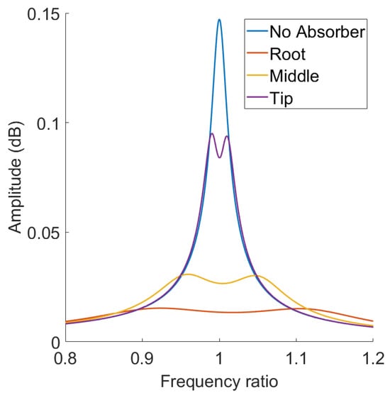
Figure 8.
Frequency response plots of the beam’s tip point without and with a shunt circuit absorber located at the beam’s root, middle, and tip [130].
Some comments about the model’s assumptions, limitations, and possible future work are summarized below. It is worth noting that the model lacks the real-time analysis of the long-term degradation of piezo materials that can lead to an incorrect assessment of the reliability and efficiency of devices. It is advisable to integrate such effects into models through age functions of material parameters or the introduction of degradation models that depend on time, load, and temperature. Moreover, the effectiveness of piezoelectric shunts is likely to be significantly affected by the geometry of the piezo plates, so it is possible that generalizations without analyzing geometric variability may lead to incorrect conclusions, especially when scaling up systems. Therefore, it is important to integrate this geometry dependence into the model. The above is an opportunity for the future development of mathematical models. The current model accounts for the piezo plate’s geometry, namely, the plates’ length, width, and thickness, as per Equations (24) and (25) that determine the shunt capacitance and the electromechanical coupling coefficient as functions of the geometry, the material of the piezoelectric patch, and the concerned mode of vibration. The question is to what extent does variability in the geometry of piezo plates affect generalized conclusions about their efficiency, especially when scaling up systems? This remains an open research question for future developments.
4.3. Inducing Internal Resonances into the System
The internal resonance depends on the coupling between two modes whose frequency ratio is an integer. To introduce a 2:1 internal resonance, the modes should have a quadratically nonlinear coupling. Nonlinearity can be induced in active systems by quadratic feedback and control signals [101] in order to activate the saturation phenomenon. In fact, the saturation phenomenon locks one mode’s energy and transfers the additional input energy to the other mode, which is extremely helpful in vibration attenuation applications. Also, nonlinearity can be induced in passive and semi-active systems by using nonlinear electrical components such as nonlinear capacitors, in which their capacitance depends inversely on the amplitude of the charge. The implementation of the nonlinear capacitor in the shunt circuit can be represented as follows:
where Equation (27) becomes
By performing the nondimensionalizing and the electro-mechanical modal expansion as demonstrated in [128], the system of equations representing the system in the modal coordinates is given as follows:
Numerically simulating the system of equations, Al-Souqi et al. [106] found the amplitude–force response and the time history of the host beam and the absorber as shown in Figure 9 and Figure 10, respectively. It is evident that tuning the absorber’s frequency to achieve the 2:1 internal resonance is efficient in suppressing the beam’s vibration via the saturation phenomenon and transferring the energy to the absorber [106]. Taking the geometric nonlinearity into account, the tuned absorber proves to be effective in suppressing the nonlinear vibration, as shown in Figure 11.
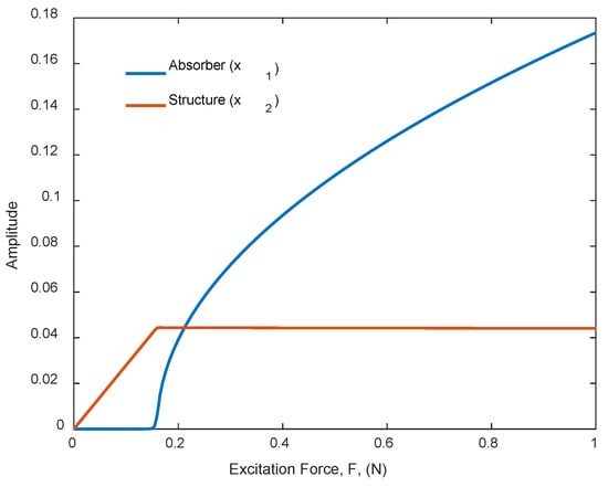
Figure 9.
The force–response plots for the modal coordinates and , [106].
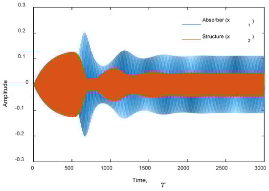
Figure 10.
The time response for the modal coordinates and , [106].
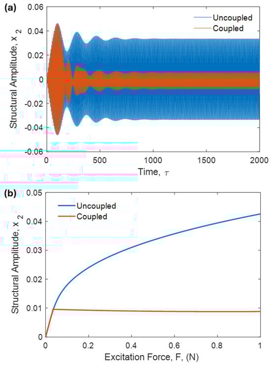
Figure 11.
The nonlinear response of the uncoupled and coupled beam: (a) time history and (b) the force response [106].
5. Conclusions and Future Work
Piezoelectric shunt circuits have proven to be an effective and versatile method for vibration suppression, with applications spanning structural control, noise reduction, and specific industrial systems. Recent developments in semi-active systems, multi-mode circuits, and energy harvesting have enhanced their adaptability and efficiency. However, challenges like large capacitor issues and the need for adaptive systems highlight areas for future research, promising further advancements in sustainable and intelligent vibration control technologies. Piezoelectric shunt circuits are a passive or semi-active method to reduce vibrations in structures by using piezoelectric materials. These materials generate electricity when mechanically stressed, and the shunt circuit dissipates this energy, damping vibrations. This technology is widely used in engineering to improve performance and reduce noise, with applications in beams, plates, and complex systems like helicopter rotor blades. There are several types of shunt circuits, each with specific uses: resistive (R) shunt that is simple, effective for single-mode damping, like in basic structural beams; resonant (RL) shunt that includes a resistor and inductor, tuned for multi-mode damping, used in panels and machinery; negative capacitance shunt that is applied in advanced noise control systems. While resonant shunts excel at targeted damping, emerging broadband and adaptive techniques promise greater flexibility. Continued innovation in circuit design and materials will likely expand their adoption across industries, making them a cornerstone of modern vibration mitigation strategies.
Recent papers explore optimizing the placement and geometry of the patch. Key areas of study include the strategic placement and geometric configuration of the piezoelectric patches to maximize efficiency. Additionally, researchers have explored advanced methods to control nonlinear structures, such as leveraging the system’s internal resonances or incorporating a negative inductor to enhance performance. These approaches aim to address challenges associated with nonlinear vibrations, which are often more complex and difficult to manage than linear ones. Another significant area of exploration has been the development of techniques to control multiple vibration modes simultaneously. This is particularly important for systems that exhibit complex dynamic behaviors across a range of frequencies. Recent studies have also presented refined mathematical models, including the discretization of continuous systems, to better understand and predict the behavior of nonlinear structures.
Based on current trends and gaps in the field, some potential future research points on piezoelectric shunts for vibration suppression are summarized below. These studies aim to address current limitations, such as narrow bandwidth, energy efficiency, and scalability, while leveraging emerging technologies like AI and smart materials.
- Universal Assessment of PSCs: Assess the feasibility of the PSCs against environmental variations. In other words, specifics of the mechanical and material environment, in particular, stiffness, weight, damping properties, and structural strength. This raises the following question: Does applied typologization allow for a universal assessment when comparing the performance between lightweight composites and massive shells, where different frequency ranges and vibration transmission mechanisms dominate? This remains an open question for research efforts.
- Degradation Models: Integrate real-time analysis of the long-term degradation of piezo materials into models for better assessment of the reliability and efficiency of devices. This may include functions of material parameters or the introduction of degradation models that depend on time, load, and temperature
- Adaptive and Self-Tuning Shunt Circuits: Develop shunt circuits that dynamically adjust their electrical parameters (e.g., resistance, inductance) in real-time to optimize damping across a wide range of frequencies and operating conditions, using machine learning or advanced control algorithms.
- Nonlinear Shunt Designs: Investigate nonlinear shunt circuits (e.g., negative capacitance or synchronized switch damping) to enhance broadband vibration suppression and improve performance under varying excitation amplitudes.
- Hybrid Shunt Systems: Explore combining passive, semi-active, and active shunt techniques to achieve a balance between energy efficiency, robustness, and high damping performance, particularly for complex structures.
- Energy Harvesting Integration: Research dual-purpose piezoelectric systems that simultaneously suppress vibrations and harvest energy, optimizing shunt circuits to maximize energy efficiency while maintaining effective damping. Combining shunts with energy harvesting circuits could power sensors, creating self-sustaining systems.
- Multimodal Vibration Control: Develop shunts capable of targeting multiple vibration modes simultaneously, using advanced multi-resonant circuits or distributed piezoelectric networks for complex structures like aerospace components or bridges.
- Miniaturization and Integration: Focus on compact, lightweight shunt circuits for micro-scale applications, such as MEMS devices, ensuring compatibility with small-scale piezoelectric transducers without sacrificing performance.
- Robustness to Environmental Variations: Study the effects of temperature, humidity, and material degradation on shunt performance, and design circuits that maintain stability and effectiveness under harsh environmental conditions.
- Smart Materials and Metamaterials: Investigate the integration of piezoelectric shunts with smart materials or mechanical metamaterials to create adaptive structures with enhanced vibration suppression capabilities.
- Real-Time Monitoring and Feedback: Incorporate sensors and IoT-based monitoring into shunt systems to provide real-time feedback on vibration levels and shunt performance, enabling predictive maintenance and optimization.
- Scalability for Large Structures: Address challenges in scaling shunt damping systems for large-scale applications (e.g., skyscrapers, wind turbines), focusing on cost-effective designs and distributed control strategies. The question is to what extent does variability in the geometry of piezo plates affect generalized conclusions about their efficiency? The effectiveness of piezoelectric shunts is likely to be significantly affected by the geometry of the plates, so it is possible that generalizations without analyzing geometric variability may lead to incorrect conclusions, especially when scaling up systems. Therefore, it is important to integrate this geometry dependence into the model.
- Bio-Inspired Shunt Designs: Explore bio-inspired approaches, such as mimicking natural damping mechanisms, Harrison mechanisms in organisms, to design novel shunt architectures that improve adaptability and efficiency.
- AI-Optimized Shunt Parameter Design: Use artificial intelligence and optimization techniques to design shunt circuits tailored to specific structures, predicting optimal circuit parameters for maximum damping with minimal computational cost.
Author Contributions
Conceptualization, K.A.-S., K.K. and S.E.; methodology, K.A.-S., K.K. and S.E.; software, S.E.; validation, K.A.-S. and K.K.; formal analysis, K.A.-S. and K.K.; investigation, K.A.-S. and K.K.; resources, S.E.; data curation, K.A.-S. and K.K.; writing—original draft preparation, K.A.-S. and K.K.; writing—review and editing, S.E.; visualization, S.E.; supervision, S.E.; project administration, S.E.; funding acquisition, S.E. All authors have read and agreed to the published version of the manuscript.
Funding
This research received no external funding.
Institutional Review Board Statement
Not applicable.
Informed Consent Statement
Not applicable.
Data Availability Statement
No new data were created or analyzed in this study.
Conflicts of Interest
The authors declare no conflicts of interest.
References
- Liu, C.; Chena, L.; Lee, H.P.; Yang, Y.; Zhang, X. Review of the inerter and inerter-based vibration isolation: Theory, devices, and applications. J. Frankl. Inst. 2022, 359, 7677–7707. [Google Scholar] [CrossRef]
- Landar, S.; Velychkovych, A.; Ropyak, L.; Andrusyak, A. Method for applying the use of a smart 4 controller for the assessment of drill string bottom-part vibrations and shock loads. Vibration 2024, 7, 802–828. [Google Scholar] [CrossRef]
- Velychkovych, A.; Mykhailiuk, V.; Andrusyak, A. Numerical model for studying the properties of a new friction damper developed based on the shell with a helical cut. Appl. Mech. 2025, 6, 1. [Google Scholar] [CrossRef]
- Shatskyi, I.; Velychkovych, A. Analytical Model of Structural Damping in Friction Module of Shell Shock Absorber Connected to Spring. Shock Vib. 2023, 1, 4140583. [Google Scholar] [CrossRef]
- Gripp, J.A.B.; Rade, D.A. Vibration and noise control using shunted piezoelectric transducers: A review. Mech. Syst. Signal Process. 2018, 112, 359–383. [Google Scholar] [CrossRef]
- Marakakis, K.; Tairidis, G.K.; Koutsianitis, P.; Stavroulakis, G.E. Shunt Piezoelectric Systems for Noise and Vibration Control: A Review. Front. Built Environ. 2019, 5, 64. [Google Scholar] [CrossRef]
- Sodano, H.A.; Inman, D.J.; Park, G. A review of power harvesting from vibration using piezoelectric materials. Shock Vib. Dig. 2004, 36, 197–206. [Google Scholar] [CrossRef]
- Zhu, M.; Shi, Q.; He, T.; Yi, Z.; Ma, Y.; Yang, B.; Chen, T.; Lee, C. Self-powered and self-functional cotton sock using piezoelectric and triboelectric hybrid mechanism for healthcare and sports monitoring. ACS Nano 2019, 13, 1940–1952. [Google Scholar] [CrossRef]
- Deng, W.; Yihao, Z.; Libanori, A.; Chen, G.; Yang, W.; Chen, J. Piezoelectric nanogenerators for personalized healthcare. Chem. Soc. Rev. 2022, 51, 3380–3435. [Google Scholar] [CrossRef]
- Erturk, A.; Inman, D.J. Piezoelectric Energy Harvesting; John Wiley & Sons: Hoboken, NJ, USA, 2011. [Google Scholar]
- Tzou, H.S.; Tseng, C.I. Distributed piezoelectric sensor/actuator design for dynamic measurement/control of distributed parameter systems: A piezoelectric finite element approach. J. Sound Vib. 1990, 138, 17–34. [Google Scholar] [CrossRef]
- Forward, R.L. Electronic damping of vibrations in optical structures. Appl. Opt. 1979, 18, 690–697. [Google Scholar] [CrossRef] [PubMed]
- Chung, D.D.L. Review: Materials for vibration damping. J. Mater. Sci. 2001, 36, 5733–5737. [Google Scholar] [CrossRef]
- Ji, H.; Qiu, J.; Wu, Y.; Zhang, C. Semi-active vibration control based on synchronously switched piezoelectric actuators. Int. J. Appl. Electromagn. Mech. 2019, 59, 299–307. [Google Scholar] [CrossRef]
- Baz, A. Vibration Damping; John Wiley & Sons: Hoboken, NJ, USA, 2018; pp. 1–10. [Google Scholar] [CrossRef]
- Hagood, N.W.; von Flotow, A. Damping of structural vibrations with piezoelectric materials and passive electrical networks. J. Sound Vib. 1991, 146, 243–268. [Google Scholar] [CrossRef]
- Thomas, O.; Ducarne, J.; Deü, J. Performance of piezoelectric shunts for vibration reduction. Smart Mater. Struct. 2012, 21, 015008. [Google Scholar] [CrossRef]
- Yamada, K. Complete passive vibration suppression using multi-layered piezoelectric element, inductor, and resistor. J. Sound Vib. 2017, 387, 16–35. [Google Scholar] [CrossRef]
- Lossouarn, B.; Aucejo, M.; Deü, J.-F.; Multon, B. Design of inductors with high inductance values for resonant piezoelectric damping. Sens. Actuators A Phys. 2017, 259, 68–76. [Google Scholar] [CrossRef]
- Park, H. Dynamics modelling of beams with shunt piezoelectric elements. J. Sound Vib. 2003, 268, 115–129. [Google Scholar] [CrossRef]
- Wu, S. Piezoelectric shunts with a parallel RL circuit for structural damping and vibration control. In Proceedings of the Smart Structures and Materials 1996: Passive Damping and Isolation, San Diego, CA, USA, 26–27 February 1996. [Google Scholar]
- Darleux, R.; Lossouarn, B.; Deü, J. Passive self-tuning inductor for piezoelectric shunt damping considering temperature variations. J. Sound Vib. 2018, 432, 105–118. [Google Scholar] [CrossRef]
- Pernod, L.; Lossouarn, B.; Astolfi, J.-A.; Deü, J.-F. Vibration damping of marine lifting surfaces with resonant piezoelectric shunts. J. Sound Vib. 2021, 496, 115921. [Google Scholar] [CrossRef]
- Liu, X.; Fan, Y.; Li, L.; Yu, X. Improving aeroelastic stability of bladed disks with topologically optimized piezoelectric materials and intentionally mistuned shunt capacitance. Materials 2022, 15, 1309. [Google Scholar] [CrossRef] [PubMed]
- Wu, Y.; Li, L.; Fan, Y.; Zucca, S.; Gastaldi, C.; Ma, H. Design of dry friction and piezoelectric hybrid ring dampers for integrally bladed disks based on complex nonlinear modes. Comput. Struct. 2020, 233, 106237. [Google Scholar] [CrossRef]
- Morad, M.; Kamel, M.; Khalil, M.K. Vibration damping of aircraft propeller blades using shunt piezoelectric transducers. IOP Conf. Ser. Mater. Sci. Eng. 2021, 1172, 012007. [Google Scholar] [CrossRef]
- Wang, C.; Yao, G.; Liu, M. Passive vibration control of subsonic thin plate via nonlinear capacitance and negative capacitance coupled piezoelectric shunt damping. Thin-Walled Struct. 2024, 198, 111656. [Google Scholar] [CrossRef]
- Yamada, K.; Matsuhisa, H.; Utsuno, H.; Sawada, K. Optimum tuning of series and parallel LR circuits for passive vibration suppression using piezoelectric elements. J. Sound Vib. 2010, 329, 5036–5057. [Google Scholar] [CrossRef]
- Rodrigues, G.K.; Gardonio, P.; Bo, L.D.; Turco, E. Piezoelectric patch vibration control unit connected to a self-tuning RL-shunt set to maximise electric power absorption. J. Sound Vib. 2022, 536, 117154. [Google Scholar] [CrossRef]
- Sugino, C.; Ruzzene, M.; Erturk, A. Design and analysis of piezoelectric metamaterial beams with synthetic impedance shunt circuits. IEEE/ASME Trans. Mechatron. 2018, 23, 2144–2155. [Google Scholar] [CrossRef]
- Ikegame, T.; Takagi, K.; Inoue, T. Exact solutions to H∞ and H2 optimizations of passive resonant shunt circuit for electromagnetic or piezoelectric shunt damper. J. Vib. Acoust. 2019, 141, 031015. [Google Scholar] [CrossRef]
- Dai, S.; Zheng, Y.; Qu, Y. Programmable piezoelectric meta-rings with high-order digital circuits for suppressing structural and acoustic responses. Mech. Syst. Signal Process. 2023, 200, 110517. [Google Scholar] [CrossRef]
- Heuss, O.; Salloum, R.; Mayer, D.; Melz, T. Tuning of a vibration absorber with shunt piezoelectric transducers. Arch. Appl. Mech. 2016, 86, 1715–1732. [Google Scholar] [CrossRef]
- Matveenko, V.P.; Iurlova, N.A.; Oshmarin, D.A.; Sevodina, N.V.; Iurlov, M.A. An approach to determination of shunt circuits parameters for damping vibrations. Int. J. Smart Nano Mater. 2018, 9, 135–149. [Google Scholar] [CrossRef]
- Toftekær, J.F.; Benjeddou, A.; Høgsberg, J. General numerical implementation of a new piezoelectric shunt tuning method based on the effective electromechanical coupling coefficient. Mech. Adv. Mater. Struct. 2020, 27, 1908–1922. [Google Scholar] [CrossRef]
- Gardonio, P.; Rodrigues, G.K.; Bo, L.D.; Turco, E. Extremum seeking online tuning of a piezoelectric vibration absorber based on the maximisation of the shunt electric power absorption. Mech. Syst. Signal Process. 2022, 176, 109171. [Google Scholar] [CrossRef]
- Jeon, J. Passive vibration damping enhancement of piezoelectric shunt damping system using optimization approach. J. Mech. Sci. Technol. 2009, 23, 1435–1445. [Google Scholar] [CrossRef]
- Jeon, J. Passive acoustic radiation control for a vibrating panel with piezoelectric shunt damping circuit using particle swarm optimization algorithm. J. Mech. Sci. Technol. 2009, 23, 1446–1455. [Google Scholar] [CrossRef]
- Wahid, N.; Muthalif, A.G.; Nor, K.A. Investigating negative capacitance shunt circuit for broadband vibration damping and utilizing ACO for optimization. Int. J. Circuits Electron. 2016, 1, 168–173. [Google Scholar]
- Caruso, G. A critical analysis of electric shunt circuits employed in piezoelectric passive vibration damping. Smart Mater. Struct. 2001, 10, 1059. [Google Scholar] [CrossRef]
- Soltani, P.; Kerschen, G.; Tondreau, G.; Deraemaeker, A. Piezoelectric vibration damping using resonant shunt circuits: An exact solution. Smart Mater. Struct. 2014, 23, 125014. [Google Scholar] [CrossRef]
- Wu, S. Method for multiple-mode shunt damping of structural vibration using a single PZT transducer. In Smart Structures and Materials 1998: Passive Damping and Isolation; SPIE: Bellingham, WA, USA, 1998. [Google Scholar]
- Hollkamp, J.J. Multimodal passive vibration suppression with piezoelectric materials and resonant shunts. J. Intell. Mater. Syst. Struct. 1994, 5, 49–57. [Google Scholar] [CrossRef]
- Wu, S. Method for multiple mode piezoelectric shunting with single PZT transducer for vibration control. J. Intell. Mater. Syst. Struct. 1998, 9, 991–998. [Google Scholar] [CrossRef]
- Behrens, S.; Fleming, A.J.; Moheimani, S. A broadband controller for shunt piezoelectric damping of structural vibration. Smart Mater. Struct. 2003, 12, 18. [Google Scholar] [CrossRef]
- Behrens, S.; Moheimani, S.R.; Fleming, A.J. Multiple mode current flowing passive piezoelectric shunt controller. J. Sound Vib. 2003, 266, 929–942. [Google Scholar] [CrossRef]
- dell’Isola, F.; Maurini, C.; Porfiri, M. Passive damping of beam vibrations through distributed electric networks and piezoelectric transducers: Prototype design and experimental validation. Smart Mater. Struct. 2004, 13, 299. [Google Scholar] [CrossRef]
- Fleming, J.; Moheimani, S.R. Control orientated synthesis of high-performance piezoelectric shunt impedances for structural vibration control. IEEE Trans. Control Syst. Technol. 2004, 13, 98–112. [Google Scholar] [CrossRef]
- Tairidis, G.K. Vibration control of smart composite structures using shunt piezoelectric systems and neuro-fuzzy techniques. J. Vib. Control 2019, 25, 2397–2408. [Google Scholar] [CrossRef]
- Raze, G.; Paknejad, A.; Zhao, G.; Collette, C.; Kerschen, G. Multimodal vibration damping using a simplified current blocking shunt circuit. J. Intell. Mater. Syst. Struct. 2020, 31, 1731–1747. [Google Scholar] [CrossRef]
- Raze, G.; Dietrich, J.; Kerschen, G. Passive control of multiple structural resonances with piezoelectric vibration absorbers. J. Sound Vib. 2021, 515, 116490. [Google Scholar] [CrossRef]
- Ribeiro, L.P.; de Lima, A.M.G. Robust passive control methodology and aeroelastic behavior of composite panels with multimodal shunt piezoceramics in parallel. Compos. Struct. 2021, 262, 113348. [Google Scholar] [CrossRef]
- Lesieutre, G.A. Vibration damping and control using shunt piezoelectric materials. Shock Vib. Dig. 1998, 30, 187–195. [Google Scholar] [CrossRef]
- Tylikowski, A. Control of circular plate vibrations via piezoelectric actuators shunt with a capacitive circuit. Thin-Walled Struct. 2001, 39, 83–94. [Google Scholar] [CrossRef]
- Park, H.; Kabeya, K.; Inman, D.J. Enhanced piezoelectric shunt design. In Proceedings of the ASME International Mechanical Engineering Congress and Exposition, New Orleans, LA, USA, 17 November 2002. [Google Scholar]
- Park, H.; Inman, D.J. Enhanced piezoelectric shunt design. Shock Vib. 2003, 10, 127–133. [Google Scholar] [CrossRef]
- Berardengo, M.; Høgsberg, J.; Manzoni, S.; Vanali, M.; Brandt, A.; Godi, T. LRLC-shunt piezoelectric vibration absorber. J. Sound Vib. 2020, 474, 115268. [Google Scholar] [CrossRef]
- Park, C.H.; Park, H.C. Multiple-mode structural vibration control using negative capacitive shunt damping. KSME Int. J. 2003, 17, 1650–1658. [Google Scholar] [CrossRef]
- Billon, K.; Montcoudiol, N.; Aubry, A.; Pascual, R.; Mosco, F.; Jean, F.; Pezerat, C.; Bricault, C.; Chesne, S. Vibration isolation and damping using a piezoelectric flextensional suspension with a negative capacitance shunt. Mech. Syst. Signal Process. 2020, 140, 106696. [Google Scholar] [CrossRef]
- Pohl, M. An adaptive negative capacitance circuit for enhanced performance and robustness of piezoelectric shunt damping. J. Intell. Mater. Syst. Struct. 2017, 28, 2633–2650. [Google Scholar] [CrossRef]
- Berardengo, M.; Manzoni, S.; Thomas, O.; Giraud-Audine, C.; Drago, L.; Marelli, S.; Vanali, M. The reduction of operational amplifier electrical outputs to improve piezoelectric shunts with negative capacitance. J. Sound Vib. 2021, 506, 116163. [Google Scholar] [CrossRef]
- Wang, T.; Dupont, J.; Tang, J. On integration of vibration suppression and energy harvesting through piezoelectric shunting with negative capacitance. IEEE/ASME Trans. Mechatron. 2023, 28, 2621–2632. [Google Scholar] [CrossRef]
- Wu, Y.G.; Wang, H.; Fan, Y.; Li, L. On the network of synchronized switch damping for blisks. Mech. Syst. Signal Process. 2023, 184, 109695. [Google Scholar] [CrossRef]
- Larson, G.D. The Analysis and Realization of a State-Switched Acoustic Transducer; Georgia Institute of Technology: Atlanta, GA, USA, 1996. [Google Scholar]
- Richard, C.; Guyomar, D.; Audigier, D.; Ching, G. Semi-passive damping using continuous switching of a piezoelectric device. In Smart Structures and Materials 1999: Passive Damping and Isolation; SPIE: Bellingham, WA, USA, 1999. [Google Scholar]
- Richard, C.; Guyomar, D.; Audigier, D.; Bassaler, H. Enhanced semi-passive damping using continuous switching of a piezoelectric device on an inductor. In Smart Structures and Materials 2000: Damping and Isolation; SPIE: Bellingham, WA, USA, 2000. [Google Scholar]
- Clark, W.W. Semi-active vibration control with piezoelectric materials as variable-stiffness actuators. In Smart Structures and Materials 1999: Passive Damping and Isolation; SPIE: Bellingham, WA, USA, 1999. [Google Scholar]
- Clark, W.W. Vibration control with state-switched piezoelectric materials. J. Intell. Mater. Syst. Struct. 2000, 11, 263–271. [Google Scholar] [CrossRef]
- Wu, Y.; Li, L.; Fan, Y.; Liu, J.; Gao, Q. A linearised analysis for structures with synchronized switch damping. IEEE Access 2019, 7, 133668–133685. [Google Scholar] [CrossRef]
- Liu, J.; Li, L.; Fan, Y. A comparison between the friction and piezoelectric synchronized switch dampers for blisks. J. Intell. Mater. Syst. Struct. 2018, 29, 2693–2705. [Google Scholar] [CrossRef]
- Qi, R.; Wang, L.; Jin, J.; Yuan, L.; Zhang, D.; Ge, Y. Enhanced Semi-active piezoelectric vibration control method with shunt circuit by energy dissipations switching. Mech. Syst. Signal Process. 2023, 201, 110671. [Google Scholar] [CrossRef]
- Guyomar, D.; Richard, C.; Petit, L. Non-linear system for vibration damping. In Proceedings of the 142th Meeting of Acoustical Society of America, Fort Lauderdale, FA, USA, 3–7 December 2001. [Google Scholar]
- Corr, L.R.; Clark, W.W. A novel semi-active multi-modal vibration control law for a piezoceramic actuator. J. Vib. Acoust. 2003, 125, 214–222. [Google Scholar] [CrossRef]
- Ji, H.; Qiu, J.; Zhu, K. Semi-active vibration control of a composite beam using an adaptive SSDV approach. J. Intell. Mater. Syst. Struct. 2009, 20, 401–412. [Google Scholar]
- Kelley, C.R.; Kauffman, J.L. Adaptive synchronized switch damping on an inductor: A self-tuning switching law. Smart Mater. Struct. 2017, 26, 035032. [Google Scholar] [CrossRef]
- Fan, Y.; Hu, Y.; Wu, Y.; Li, L. Mechanism of interconnected synchronized switch damping for vibration control of blades. Chin. J. Aeronaut. 2023, 36, 207–228. [Google Scholar]
- Petit, L.; Lefeuvre, E.; Richard, C.; Guyomar, D. A broadband semi passive piezoelectric technique for structural damping. In Proceedings of the Smart Structures and Materials 2004: Damping and Isolation, Newport Beach, CA, USA, 24 July 2004. [Google Scholar]
- Lefeuvre, E.; Badel, A.; Petit, L.; Richard, C.; Guyomar, D. Semi-passive piezoelectric structural damping by synchronized switching on voltage sources. J. Intell. Mater. Syst. Struct. 2006, 17, 653–660. [Google Scholar] [CrossRef]
- Faiz, A.; Guyomar, D.; Petit, L.; Buttay, C. Wave transmission reduction by a piezoelectric semi-passive technique. Sens. Actuators A Phys. 2006, 128, 230–237. [Google Scholar] [CrossRef]
- Badel, A.; Sebald, G.; Guyomar, D.; Lallart, M.; Lefeuvre, E.; Richard, C.; Qiu, J. Piezoelectric vibration control by synchronized switching on adaptive voltage sources: Towards wideband semi-active damping. J. Acoust. Soc. Am. 2006, 119, 2815–2825. [Google Scholar] [CrossRef]
- Bao, B.; Tang, W. Semi-active vibration control featuring a self-sensing SSDV approach. Measurement 2017, 104, 192–203. [Google Scholar] [CrossRef]
- Zheng, L.; He, Y.; Fan, L.; Cao, H.; Chen, X. Semi-active vibration control of the motorized spindle using a self-powered SSDV technique: Simulation and experimental study. Autom. Časopis Autom. Mjer. Elektron. Računarstvo I Komun. 2022, 63, 511–524. [Google Scholar] [CrossRef]
- Ji, H.; Qiu, J.; Cheng, J.; Inman, D. Application of a Negative Capacitance Circuit in Synchronized Switch Damping Techniques for Vibration Suppression. In Active and Passive Smart Structures and Integrated Systems 2010; SPIE: Bellingham, WA, USA, 2011. [Google Scholar]
- Cheng, J.; Ji, H.; Qiu, J.; Takagi, T. Semi-active vibration suppression by a novel synchronized switch circuit with negative capacitance. Int. J. Appl. Electromagn. Mech. 2011, 37, 291–308. [Google Scholar] [CrossRef]
- Tang, W.; Wang, L.-B.; Ren, Y.-M.; Bao, B.; Cao, J.-J. Design and experimental analysis of self-sensing SSDNC technique for semi-active vibration control. Smart Mater. Struct. 2018, 27, 085028. [Google Scholar] [CrossRef]
- Ji, H.; Guo, Y.; Qiu, J.; Wu, Y.; Zhang, C.; Tao, C. A new design of unsymmetrical shunt circuit with negative capacitance for enhanced vibration control. Mech. Syst. Signal Process. 2021, 155, 107576. [Google Scholar] [CrossRef]
- Agnes, G.S.; Inman, D.J. Nonlinear piezoelectric vibration absorbers. Smart Mater. Struct. 1996, 5, 704. [Google Scholar] [CrossRef]
- Soltani, P.; Kerschen, G. The nonlinear piezoelectric tuned vibration absorber. Smart Mater. Struct. 2015, 24, 075015. [Google Scholar] [CrossRef]
- Lossouarn, B.; Deü, J.; Kerschen, G. A fully passive nonlinear piezoelectric vibration absorber. Philos. Trans. R. Soc. A Math. Phys. Eng. Sci. 2018, 376, 20170142. [Google Scholar] [CrossRef]
- Lossouarn, B.; Kerschen, G.; Deü, J. An analogue twin for piezoelectric vibration damping of multiple nonlinear resonances. J. Sound Vib. 2021, 511, 116323. [Google Scholar] [CrossRef]
- Raze, G.; Jadoul, A.; Guichaux, S.; Broun, V.; Kerschen, G. A digital nonlinear piezoelectric tuned vibration absorber. Smart Mater. Struct. 2019, 29, 015007. [Google Scholar] [CrossRef]
- Alfahmi, O.; Sugino, C.; Erturk, A. Duffing-type digitally programmable nonlinear synthetic inductance for piezoelectric structures. Smart Mater. Struct. 2022, 31, 095044. [Google Scholar] [CrossRef]
- Alfahmi, O.; Erturk, A. Programmable hardening and softening cubic inductive shunts for piezoelectric structures: Harmonic balance analysis and experiments. J. Sound Vib. 2024, 571, 118029. [Google Scholar] [CrossRef]
- Geng, X.F.; Ding, H.; Ji, J.C.; Wei, K.X.; Jing, X.J.; Chen, L.Q. A state-of-the-art review on the dynamic design of nonlinear energy sinks. Eng. Struct. 2024, 313, 118228. [Google Scholar] [CrossRef]
- Viguié, R.; Kerschen, G.; Ruzzene, M. Exploration of nonlinear shunting strategies as effective vibration absorbers. In Active and Passive Smart Structures and Integrated Systems 2009; SPIE: Bellingham, WA, USA, 2009. [Google Scholar]
- Zhou, B.; Thouverez, F.; Lenoir, D. Essentially nonlinear piezoelectric shunt circuits applied to mistuned bladed disks. J. Sound Vib. 2014, 333, 2520–2542. [Google Scholar] [CrossRef]
- Silva, T.M.; Clementino, M.A.; De Marqui, C.; Erturk, A. An experimentally validated piezoelectric nonlinear energy sink for wideband vibration attenuation. J. Sound Vib. 2018, 437, 68–78. [Google Scholar] [CrossRef]
- Dekemele, K.; Giraud-Audine, C.; Thomas, O. A piezoelectric nonlinear energy sink shunt for vibration damping. Mech. Syst. Signal Process. 2024, 220, 111615. [Google Scholar] [CrossRef]
- Zhou, K.; Hu, Z. Vibration suppression on the composite laminated plates subjected to aerodynamic and harmonic excitations based on the nonlinear piezoelectric shunt damping. Appl. Math. Model. 2023, 121, 134–165. [Google Scholar] [CrossRef]
- Mangussi, F.; Zanette, D.H. Internal resonance in a vibrating beam: A zoo of nonlinear resonance peaks. PLoS ONE 2016, 11, e0162365. [Google Scholar] [CrossRef]
- Nayfeh, H.; Mook, D.T.; Marshall, L.R. Nonlinear coupling of pitch and roll modes in ship motions. J. Hydronautics 1973, 7, 145–152. [Google Scholar] [CrossRef]
- Shami, Z.A.; Giraud-Audine, C. A nonlinear piezoelectric shunt absorber with 2: 1 internal resonance: Experimental proof of concept. Smart Mater. Struct. 2022, 31, 035006. [Google Scholar] [CrossRef]
- Shami, Z.A.; Giraud-Audine, C.; Thomas, O. A nonlinear piezoelectric shunt absorber with a 2: 1 internal resonance: Theory. Mech. Syst. Signal Process. 2022, 170, 108768. [Google Scholar] [CrossRef]
- Shami, Z.A.; Shen, Y.; Giraud-Audine, C.; Touzé, C.; Thomas, O. Nonlinear dynamics of coupled oscillators in 1: 2 internal resonance: Effects of the non-resonant quadratic terms and recovery of the saturation effect. Meccanica 2022, 57, 2701–2731. [Google Scholar] [CrossRef]
- Shami, Z.A.; Giraud-Audine, C.; Thomas, O. Saturation correction for a piezoelectric shunt absorber based on 2:1 internal resonance using a cubic nonlinearity. Smart Mater. Struct. 2023, 32, 055024. [Google Scholar] [CrossRef]
- Al-Souqi, K. Exploiting the Internal Resonance in Shunted-Circuit Based Vibration Suppression. Master’s Thesis, American University of Sharjah, Sharjah, United Arab Emirates, 2024. [Google Scholar]
- Wang, T.; Tang, J. Elucidating negative capacitance design in piezoelectric circuitry to facilitate vibration suppression enhancement assisted by energy harvesting. J. Sound Vib. 2025, 606, 119000. [Google Scholar] [CrossRef]
- Shao, S.; Chen, J.; Wu, Z.; Zhang, Y.; Chen, J.; Xia, R.; Li, Z. Tunable flexural waves by piezoelectric metasurface with shunt circuits. Int. J. of Mech. Sci. 2024, 284, 109769. [Google Scholar] [CrossRef]
- Taşkıran, A.; Özer, B. Experimentally validated passive nonlinear capacitor in piezoelectric vibration applications. Smart Mater. Struct. 2024, 33, 105003. [Google Scholar] [CrossRef]
- Jian, Y.; Hu, G.; Tang, L.; Shen, Y.; Zhan, Y.; Aw, K. Adaptive piezoelectric metamaterial beam: Autonomous attenuation zone adjustment in complex vibration environments. Smart Mater. Struct. 2023, 32, 105023. [Google Scholar] [CrossRef]
- Shami, Z.A.; Giraud-Audine, C.; Thomas, O. A nonlinear tunable piezoelectric resonant shunt using a bilinear component: Theory and experiment. Nonlinear Dyn. 2023, 111, 7105–7136. [Google Scholar] [CrossRef]
- Zhang, Y.; Chang, D.; Yu, Z.; Sun, H.; Cheng, X.; Li, D. The vibroacoustic characteristics and regulation rules of panel–cavity–panel system controlled by piezoelectric shunt oscillators with negative capacitors. J. Sound Vib. 2023, 544, 117389. [Google Scholar] [CrossRef]
- Liu, X.; Wang, C.; Zhang, Y.; Wu, K.; Dong, B.; Huang, L. Extra sound attenuation via shunted piezoelectric resonators in a duct. Int. J. Mech. Sci. 2022, 225, 107370. [Google Scholar] [CrossRef]
- Iurlov, M.A.; Kamenskikh, A.O.; Lekomtsev, S.V.; Matveenko, V.P. Passive suppression of resonance vibrations of a plate and parallel plates assembly, interacting with a fluid. Int. J. Struct. Stab. Dyn. 2022, 22, 2250101. [Google Scholar] [CrossRef]
- Zhiwei, W.; Xiang, Z.; Tianyun, L.; Rui, N. low-frequency multimode vibration suppression of an acoustic black hole beam by shunt damping. J. Vib. Acoust. 2022, 144, 4053590. [Google Scholar]
- Mazur, K.; Rzepecki, J.; Pietruszewska, A.; Wrona, S.; Pawelczyk, M. Vibroacoustical Performance Analysis of a Rigid Device Casing with Piezoelectric Shunt Damping. Sensors 2021, 21, 2517. [Google Scholar] [CrossRef] [PubMed]
- He, H.; Tan, X.; He, J.; Zhang, F.; Chen, G. A novel ring-shaped vibration damper based on piezoelectric shunt damping: Theoretical analysis and experiments. J. Sound Vib. 2020, 468, 115125. [Google Scholar] [CrossRef]
- Silva, T.M.P.; Clementino, M.A.; de Sousa, V.C.; De Marqui, C. Junior, An experimental study of a piezoelectric metastructure with adaptive resonant shunt circuits. IEEE/ASME Trans. Mech. 2020, 25, 1083–4435. [Google Scholar] [CrossRef]
- Toftekær, J.F.; Høgsberg, J. Experimental validation of piezoelectric shunt tuning with residual mode correction: Damping of plate-like structures. J. Int. Mater. Sys. Struct. 2020, 31, 1220–1239. [Google Scholar] [CrossRef]
- Gozum, M.M.; Aghakhani, A.; Basdogan, I. An investigation of the electromechanical coupling and broadband shunt damping in composite plates with integrated piezo-patches. J. Int. Mater. Sys. Struct. 2019, 30, 3008–3024. [Google Scholar] [CrossRef]
- Ducarne, J.; Thomas, O.; Deu, J.F. Placement and dimension optimization of shunted piezoelectric patches for vibration reduction. J. Sound Vib. 2012, 331, 3286–3303. [Google Scholar] [CrossRef]
- Giorgio, I.; Culla, A.; Del Vescovo, D. Multimode vibration control using several piezoelectric transducers shunted with a multiterminal network. Arch Appl. Mech. 2009, 79, 859–879. [Google Scholar] [CrossRef]
- Marneffe, D.; Preumont, A. Vibration damping with negative capacitance shunts: Theory and experiment. Smart Mater. Struct. 2008, 17, 035015. [Google Scholar] [CrossRef]
- Niederberger, D.; Fleming, A.; Moheimani, S.O.R.; Morari, M. Adaptive multi-mode resonant piezoelectric shunt damping. Smart Mater. Struct. 2004, 13, 1025–1035. [Google Scholar] [CrossRef]
- Onoda, J.; Makihara, K.; Minesugi, K. Energy-recycling semi-active method for vibration suppression with piezoelectric transducers. AIAA J. 2003, 41, 711–719. [Google Scholar] [CrossRef]
- Hagood, N.; Chung, W.; von Flotow, A. Modeling of piezoelectric actuator dynamics for active structural control. J. Intell. Mater. Syst. Struct. 1990, 1, 327–354. [Google Scholar] [CrossRef]
- Thomas, O.; Deü, J.F.; Ducarne, J. Vibrations of an elastic structure with shunted piezoelectric patches: Efficient finite element formulation and electromechanical coupling coefficients. Int. J. Numer. Methods Eng. 2009, 80, 235–268. [Google Scholar] [CrossRef]
- Fleming, J.; Behrens, S.; Moheimani, S. Reducing the inductance requirements of piezoelectric shunt damping systems. Smart Mater. Struct. 2003, 12, 57. [Google Scholar] [CrossRef]
- Arafat, H.N.; Nayfeh, A.H.; Chin, C.M. Nonlinear nonplanar dynamics of parametrically excited cantilever beams. Nonlinear Dyn. 1998, 15, 31–61. [Google Scholar] [CrossRef]
- Kadri, K. Nonlinear Multimode Vibration Attenuation Using Passive Shunt Circuits. Master’s Thesis, American University of Sharjah, Sharjah, United Arab Emirates, 2024. [Google Scholar]
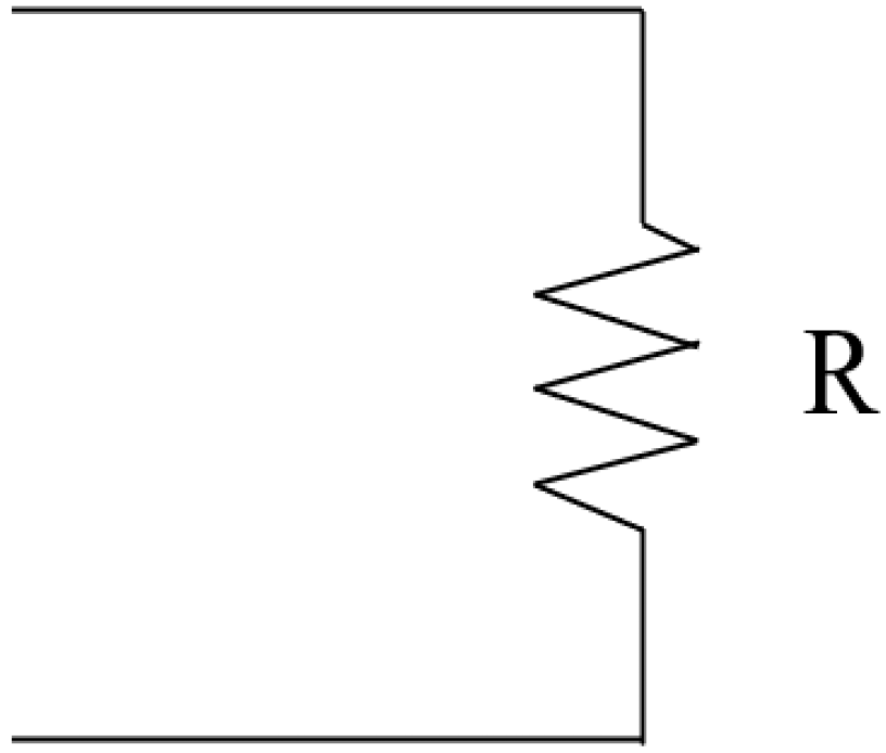
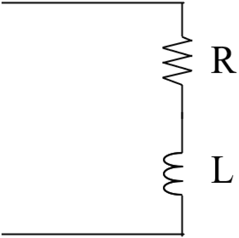
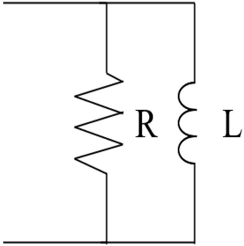
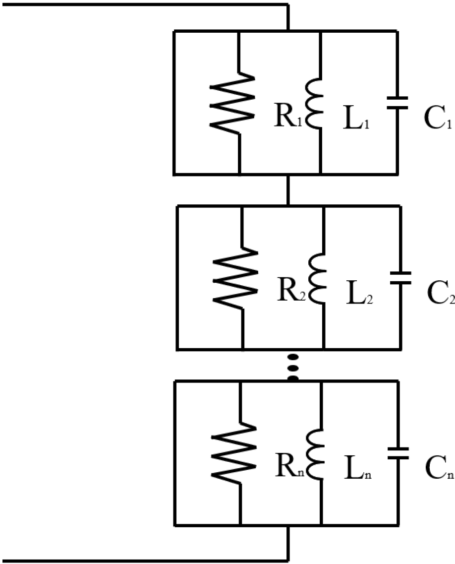
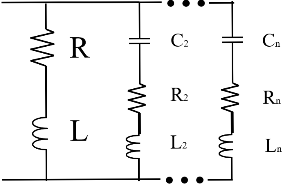
Disclaimer/Publisher’s Note: The statements, opinions and data contained in all publications are solely those of the individual author(s) and contributor(s) and not of MDPI and/or the editor(s). MDPI and/or the editor(s) disclaim responsibility for any injury to people or property resulting from any ideas, methods, instructions or products referred to in the content. |
© 2025 by the authors. Licensee MDPI, Basel, Switzerland. This article is an open access article distributed under the terms and conditions of the Creative Commons Attribution (CC BY) license (https://creativecommons.org/licenses/by/4.0/).