Abstract
Sn-based anodes for lithium-ion batteries (LIBs) offer high capacity and low cost; however, significant volume changes during lithiation/delithiation cause mechanical degradation, limiting their practical applications. Microstructural control is a key approach to mitigating these volume changes. This study reports the fabrication of core (Sn rod)-shell (mesoporous Sn-oxide layer) structures through electrodeposition followed by anodization, and their applications to anode active materials for LIBs. First, micro-Sn rods with controlled lengths and diameters were fabricated under various electrodeposition conditions. The electrodeposited Sn exhibited a dendritic structure with short secondary rods branching from a long primary rod. While the primary Sn rod diameters remained constant, the secondary rod diameters varied depending on electrodeposition parameters. Notably, rod coarsening due to secondary rod agglomeration occurred at higher currents and longer deposition durations during galvanostatic electrodeposition. In contrast, potentiostatic electrodeposition prevented agglomeration and increased the quantity of Sn rods with voltage. Subsequently, the core-shell structures were fabricated by anodizing Sn rods, forming mesoporous Sn-oxide layers with different pore sizes and pore wall thicknesses. Electrochemical characterization revealed that the core-shell anode performance for LIBs varied with the Sn-oxide shell’s microstructure. These findings provide insights into optimal core-shell structures to improve anode performance for LIBs.
1. Introduction
The demand for eco-friendly electric vehicles (EVs) has increased significantly in recent years due to stricter environmental regulations on carbon emissions [1,2]. Lithium-ion batteries (LIBs) are considered the most suitable option for EVs because of their high energy density, power density, and long cycle life [3,4,5]. However, the energy density of commercial LIBs (150–200 Wh/kg) remains insufficient to completely replace fossil fuel-based systems [5,6]. To address this limitation, significant research efforts have focused on developing next-generation electrode materials, including high-voltage cathodes and high-capacity anodes, to enhance energy density [7,8,9,10].
Among the promising anode materials, Li-alloying materials, such as silicon (Si), tin (Sn), and phosphorus (P), offer theoretical specific capacities significantly higher than graphite (372 mAh/g) [11,12,13,14]. Sn-based anodes, particularly, are attractive due to their high theoretical capacity (994 mAh/g), low cost, and non-toxic nature [15,16,17,18]. However, Sn undergoes substantial volume change (~260%) during lithiation/delithiation, which has long hindered its application in LIBs [15,16,17,18,19]. Repeated expansion and contraction of the Sn anode cause a loss of contact between the active material and the conductive additive. In severe cases, this results in the pulverization of the active material and the delamination from the current collector, which in turn causes rapid capacity fading over repeated charge-discharge cycles [19,20,21].
Various strategies have been explored to mitigate volume change issues in Sn-based anodes. Sn-alloys [15,16,17,18,22,23,24] and Sn-oxides [25,26,27,28,29,30,31,32] incorporating inert elements have been investigated as alternatives to pure Sn. In Sn-alloys, inert metals act as a buffer matrix, absorbing stress and preserving electrode integrity [15,16,17,18,22,23,24]. In Sn-oxides (SnOx), Li oxide (Li2O) formed during the initial charging also serves as a buffer matrix, helping maintain the electrode structure [25,26,27,28,29,30,31,32]. Another approach to preventing mechanical degradation is microstructural control, which involves reducing the particle size to the nanoscale or designing porous, hollow, sheet, and rod structures [16,17,18,19,29,30,31,32,33,34,35,36]. These engineered structures relieve internal stress, minimize volume changes, and improve electrochemical performance by shortening lithium-ion diffusion paths. However, most studies have relied on hydrothermal synthesis for fabricating nanoparticles, which requires high temperatures, elevated pressures, and long processing times [29,30,31,32,33]. In contrast, electrochemical approaches such as electrodeposition and anodization, which have not been widely studied, enable precise microstructural control under ambient conditions in a short time. These methods offer greater cost-effectiveness and convenience while allowing for adjustable material properties by varying electrochemical parameters [34,35,36,37,38,39].
In this study, we report the fabrication of core-shell structures, where an Sn rod is covered with a mesoporous Sn-oxide shell, using electrodeposition followed by anodization. One-dimensional (1-D) Sn micro-rods were fabricated through single-step electrodeposition under different voltages, current densities, and deposition durations. Subsequently, mesoporous Sn-oxide layers with varied pore sizes and wall thicknesses were formed on the Sn rod surface through anodization. These fabricated materials were evaluated as anode active materials for LIBs, and their electrochemical performances were analyzed in relation to Sn-oxide microstructure. Finally, we discuss the advantages and limitations of applying the core-shell structures as Sn-based anode materials for LIBs.
2. Experimental
2.1. Materials Fabrication
High-purity Sn foil (0.18 mm thick, 99.9%, Alfa Aesar, MA, USA) was used as a substrate to fabricate 1-D Sn micro-rods through electrodeposition. Prior to deposition, the foil was pretreated in diluted sulfuric acid and rinsed with distilled water to remove native oxide layers and surface contaminants. The plating bath consisted of 1.5 M H2SO4 (95.0%, Samchun Chemicals, Seoul, Republic of Korea) and 0.15 M SnSO4 (95.5%, Thermo Fisher Scientific, Waltham, MA, USA) in aqueous solution.
Electrodeposition was carried out in a beaker cell, with Sn foil as the working electrode and a platinum mesh as the counter electrode, maintaining a 2 cm distance between the electrodes [34,35]. Various current densities and deposition durations (1–5 A/cm2 for 5 s, 1–3 A/cm2 for 10 s), and voltages (4–8 V for 10 s) were applied to investigate the structural changes in the Sn rods. To form porous Sn-oxides, the as-prepared Sn rods on the Sn foil were subjected to anodization, using the same electrode setup. The process was conducted under different voltage conditions (4–10 V for 60 s) in a 1 M NaOH (97.0%, Junsei Chemical, Tokyo, Japan) aqueous solution [36,37] to achieve controlled porous structures on the Sn rod surface. Both electrodeposition and anodization were performed at room temperature using an IviumStat (Ivium Technologies, Eindhoven, The Netherlands), without electrolyte stirring or inert gas purging. These experimental conditions largely follow those reported in previous works [34,35,36,37], with notable difference in the target anodized structure.
The morphologies of the fabricated Sn rods and porous Sn-oxides were analyzed using field-emission scanning electron microscopy (FE-SEM; Mira3, TESCAN, Brno, Czech Republic), while their chemical compositions were verified using energy-dispersive X-ray spectrometry (EDS; 51-XMZ1004, Oxford Instruments, Abingdon, UK). The crystal structures of the samples were determined using an X-ray diffractometer (XRD Ultima-IV, Rigaku, Tokyo, Japan).
2.2. Fabrication and Electrochemical Tests of Electrodes and Cells
To evaluate the electrochemical characteristics of the Sn and Sn-oxide rods fabricated in Section 2.1 as anode active materials for LIBs, non-anodized Sn rods and Sn rods anodized at 6 V, 8 V, and 10 V (core(Sn)-shell(SnOx) structures) were tested. Carbon black (acetylene, 50% compressed, Alfa Aesar, Ward Hill, MA, USA) and polyvinylidene fluoride (PVdF, Mw ~ 534,000, Sigma-Aldrich, St. Louis, MO, USA) were used as the conductive additive and binder, respectively. These three components were mixed in a weight ratio of 7:2:1 and dispersed in N-methyl-2-pyrrolidinone (NMP, ≥99.0%, Sigma-Aldrich, USA) to prepare a slurry. The slurry was cast onto a copper foil (20 µm, 99.8%, Alfa Aesar, USA) using a doctor blade and dried overnight in a 60 °C oven. The dried anode was slit to a 16 mm diameter disc, with an anode loading level of 0.85 ± 0.2 mg/cm2. The prepared anode was assembled into a CR2032 coin cell in a two-electrode half-cell configuration, using lithium foil as the counter electrode and a Celgard 2400 membrane as the separator. 1 M lithium hexafluorophosphate (LiFP6) in ethylene carbonate (EC)/ethyl methyl carbonate (EMC) (3/7 v/v) + fluoroethylene carbonate (FEC) 3 wt.% (Dongwha Electrolyte, Nonsan-si, Republic of Korea) was used as the electrolyte. All cell assembly was conducted in an Ar-filled glove box (O2, H2O < 1 ppm; Glove Box, Mbraun-Unilab, Garching, Germany).
Cyclic voltammetry (CV) was performed to analyze the electrochemical properties of the porous Sn-oxide using a scan rate of 1 mV/s in the voltage range of 0.01–3 V at 25 °C. The charge/discharge characteristics, cycle life, and high-rate performance of the prepared anodes were evaluated in constant current (CC) mode in the voltage range of 0.02–1.5 V. The charge/discharge characteristics were assessed at a current density of 50 mA/g for the initial three cycles. The cycle life was further evaluated at 100 mA/g, while the rate performance was analyzed at 100, 200, 400, and 800 mA/g. All the experiments were conducted using a multichannel potentiostat/galvanostat system (VMP3, Biologic Co., Seyssinet-Pariset, Grenoble, France).
All the fabrication, characterization, and electrochemical measurements were conducted in an air-conditioned laboratory maintained at a nominal temperature of 25 °C. The ambient temperature was continuously monitored with a thermometer and remained stable throughout the experiments.
3. Results and Discussion
3.1. Sn Rod Formation Using Electrodeposition
Figure 1a–f show the surface morphologies of Sn substrate and Sn electrodeposited at various current densities for 5 s under galvanostatic conditions. The deposited Sn exhibited a dendritic structure, with multiple short secondary Sn rods extending from a long primary Sn rod. The diameters of the deposited Sn rods at each current density were quantified through image analysis and are summarized in Figure 1g. While the primary Sn rod diameter remained constant at approximately 1.35 μm, the secondary Sn rod diameter increased linearly with current density, ranging from approximately 0.58 μm at 1 A/cm2 to 1.10 μm at 5 A/cm2. It is noted that the agglomeration of the secondary rods was observed at current densities above 4 A/cm2 (yellow dashed circles in Figure 1e,f). This agglomeration is undesirable, as the study aims to utilize the 1-D micro rod morphology of Sn to mitigate volume change issues in LIB anode applications.
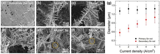
Figure 1.
SEM images of (a) Sn substrate and (b–f) Sn rods electrodeposited on the substrate for 5 s under various current densities: (b) 1, (c) 2, (d) 3, (e) 4, and (f) 5 A/cm2. (g) Variations in the diameters of primary and secondary Sn rods with current density.
In addition, when the Sn rods were electrodeposited for 10 s at current densities below 3 A/cm2 to increase the deposition amount, a similar agglomeration of Sn rods was observed (yellow dashed circles in Figure 2a–c). This suggests that to obtain individually separated Sn rods under galvanostatic conditions, both current density and deposition time must be controlled within specific limits. From a practical standpoint, this indicates that large-scale production of Sn rods through constant-current electrodeposition is significantly constrained.

Figure 2.
SEM images of Sn rods electrodeposited on Sn substrate for 10 s under various current densities: (a) 1, (b) 2, and (c) 3 A/cm2.
Figure 3a–e show the surface morphologies of Sn electrodeposited at various voltages for 10 s under potentiostatic conditions. Similar to galvanostatic deposition, dendritic structures of primary and secondary Sn rods were observed. However, unlike in galvanostatic conditions, thin secondary rods were formed without agglomeration regardless of the applied voltage. The measured diameters of the Sn rods deposited at different voltages are shown in Figure 3f, indicating that both the primary and secondary rod diameters remained nearly constant irrespective of the applied voltage. Notably, the diameters of primary (approximately 1.28 μm) and secondary (approximately 0.59 μm) Sn rods were comparable to those of Sn rods electrodeposited at 1 A/cm2 for 5 s (Figure 1a). To analyze the relationship between applied voltage and deposition amount, the electrodeposited material quantity was calculated from the current density-time profiles obtained during potentiostatic deposition (Figure 4). The results are summarized in Table 1.
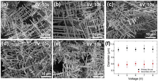
Figure 3.
SEM images of Sn rods electrodeposited on Sn substrate for 10 s under various voltages: (a) 4, (b) 5, (c) 6, (d) 7, and (e) 8 V. (f) Variations in the diameters of primary and secondary Sn rods with voltage.
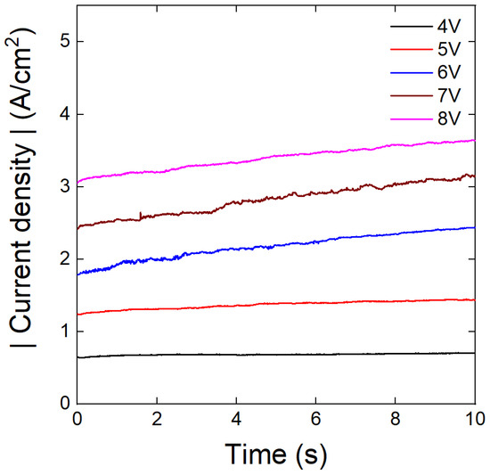
Figure 4.
Variation in the current density with electrodeposition time at different voltages, measured during potentiostatic electrodeposition.

Table 1.
Amount of Sn electrodeposits at different electrodeposition conditions.
Compared to the Sn deposition amount under galvanostatic conditions at 1 A/cm2 (10 C/cm2, ~6.16 mg Sn/cm2), the deposition amount under potentiostatic conditions increased from 6.83 C/cm2 (~4.20 mg Sn/cm2) at 4 V to 33.92 C/cm2 (~20.86 Sn/cm2) at 8 V.
In summary, under galvanostatic conditions, the diameter of the secondary rods increased with increasing current density, leading to agglomeration and preventing the synthesis of well-separated Sn rods. In contrast, under potentiostatic conditions, the diameter of secondary rods remained constant, even with increasing voltage, enabling the continuous growth of separated Sn rods without agglomeration. The observed correlation between electrodeposition mode and rod agglomeration is quite notable, but the underlying mechanisms remain unclear. Nevertheless, it is strongly suggested that this is due to differences in the actual current applied to the electrode surface, for the following reasons: During galvanostatic deposition, the surface area of Sn rods on the working electrode increases continuously with electrodeposition time. Since the apparent current remains constant, the actual current density applied to the reactive surface decreases as the electrodeposition progresses. As the current density decreases, the nucleation of new Sn rods is suppressed due to the lower nucleation driving force, favoring the growth of pre-existing rods and leading to agglomeration. In contrast, under potentiostatic conditions, a constant overpotential is maintained, ensuring a steady electrochemical reaction driving force regardless of the surface area change. This suggests that the driving forces for nucleation and rod growth remain nearly unchanged, resulting in a more consistent actual current density at the working electrode surface. The increase in the apparent current densities over potentiostatic deposition time (Figure 4) supports this explanation.
3.2. Porous Sn-Oxide Formation Using Anodic Oxidation
Porous Sn-oxide was formed on the surfaces of the Sn rods fabricated in Section 3.1 through anodization. Porous Sn-oxides typically develop when Sn2+ ions, oxidized by anodic polarization, react with oxygen ions in the electrolyte to produce a solid oxide layer, followed by an equilibrium between oxide formation and chemical oxide dissolution into the electrolyte [37,38]. The pore size is influenced by the evolution of oxygen gas during this process. When voltage is applied, Sn oxidation and oxygen evolution occur simultaneously. As the oxygen evolution rate increases, a more open porous structure is formed [36,38]. Figure 5a–g show the surface morphologies of the Sn rods anodized at different voltages. No porous oxide layers were observed at voltages of 4 V and 5 V (Figure 5a,b), whereas porous structures began to appear at voltages above 6 V (Figure 5c–g). At voltages below 5 V, the low oxidation current density likely led to a slow formation rate of the Sn-oxide layer, allowing dissolution into the electrolyte to become dominant, thereby preventing the formation of porous layers.
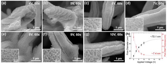
Figure 5.
SEM images of Sn-oxide formed on the Sn rod surface by anodization for 60 s under various voltages of (a) 4, (b) 5, (c) 6, (d) 7, (e) 8, (f) 9, and (g) 10 V. The inset figures in (c–g) are magnified images. (h) Variations in pore diameter and pore wall thickness of Sn-oxide at different anodizing voltages, along with black and red dotted lines indicating their respective trends.
Quantitative analysis of Sn-oxide surface characterization in samples anodized above 6 V is shown in Figure 5h. The pore diameter increased from 27.1 nm at 6 V to 62.4 nm at 10 V, while the pore wall thickness decreased from 22.7 nm to 8.2 nm. The formation of more open porous structures (wide pores) at higher anodizing voltages is most likely attributed to the enhanced oxygen evolution reaction at higher voltages [36,38]. The pore size and wall thickness of the Sn-oxide layer exhibited an exponential relationship with the anodization voltage, as indicated by the dotted lines in Figure 5h. Based on the fitted exponential curve, changes in the pore size and wall thickness became less significant above 10 V. If the anodization voltage is further increased, the pore size and wall thickness are predicted to converge at ca. 75.1 nm and 7.4 nm, respectively, which represent just 120% and 90% of the corresponding values observed at 10 V.
Figure 6a–c show the composition analysis of the anodized samples. The Sn/O atomic ratio at the surface was approximately 5.49 and 3.61 for non-porous samples anodized at 4 and 5 V, respectively, but decreased to 1.07 for porous samples anodized at 6 V. This indicates that for porous Sn-oxide formed under oxidizing conditions above 6 V, the stoichiometry is close to that of ideal stannous oxide (SnO). The crystallographic analysis indicated no significant alterations in the XRD patterns of the anodized Sn rod compared to the pristine Sn rod (Figure 6d), confirming the low crystallinity of the porous Sn-oxide layer [39]. Observation of the cross-section of specimens with oxide formation under anodizing conditions above 6 V showed a core (Sn rod)-shell (mesoporous Sn-oxide) morphology, as expected (Figure 7). Quantitative analysis of the porous Sn-oxide layer revealed that its thickness increased with anodization voltage, reaching approximately 162, 263, and 351 nm at 6, 8, and 10 V, respectively. These three specimens were evaluated as anode active materials for LIBs in the following section.
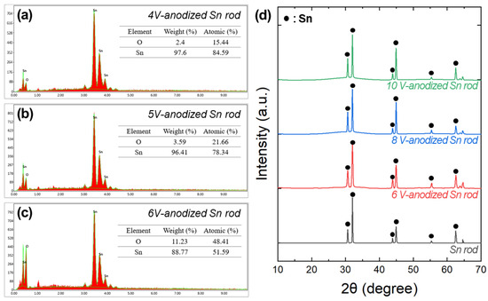
Figure 6.
EDS spectra and chemical compositions of the Sn-oxide on the Sn rods at different anodization voltages: (a) 4, (b) 5, and (c) 6 V. (d) XRD patterns of the Sn rod and anodized Sn rods. From bottom to top: electrodeposited Sn rod, Sn rods anodized at 6 V, 8 V, and 10 V, respectively.

Figure 7.
Cross-sectional morphology of core-shell rods anodized at (a) 6, (b) 8, and (c) 10 V.
3.3. Electrochemical Properties of Core (Sn Rod)-Shell (Mesoporous Sn-Oxide Layer) Anodes
The electrochemical properties of the core-shell anodes anodized at 6, 8, and 10 V were analyzed to investigate the influence of the pore size and wall thickness of Sn-oxide on electrode performance. The cyclic voltammograms presented in Figure 8a–c show a cathodic peak at approximately 0.5–0.8 V vs. Li+/Li during the first cathodic scan (denoted as A in the figures) for all three samples. This peak is attributed to the formation of a solid electrolyte interphase (SEI) layer and the reduction of SnO to Sn, leading to the formation of Li2O (SnO + 2Li+ + 2e− → Sn + Li2O) [40,41].

Figure 8.
Cyclic voltammograms of core-shell anodes anodized at (a) 6, (b) 8, and (c) 10 V. The measurements were performed at a scan rate of 1 mV/s in the voltage range of 0.01–3 V vs. Li+/Li. Representative cathodic peaks (A–C) and their pared anodic peaks (B’ and C’) are marked in the graphs.
The cathodic peak at around 0.01 V vs. Li+/Li and the anodic peak at around 0.83 V vs. Li+/Li (denoted as B and B′, respectively, in the figures) represent the reversible lithiation and delithiation reactions of Sn (Sn + xLi+ + xe− ↔ LixSn). In addition, a cathodic peak (denoted as C in the figures) appeared at approximately 1.10 V vs. Li+/Li during the second and third cathodic scans, related to the reduction of SnO to Sn and the formation of Li2O. The corresponding anodic peak (denoted as C′ in the figures) appeared around 1.58 V vs. Li+/Li. [42,43,44]. This pair of redox peaks (C and C′) suggests that the Li2O formed in the first cycle is not completely irreversible and participates in the reaction to a certain extent reversibly in subsequent cycles. The prominence of this peak increased with higher anodization voltages, as seen in peaks C and C′ of Figure 8a–c. This additional reversible process is expected to contribute to the increase in the reversible capacity of the active materials.
Figure 9a–c present the charge and discharge curves for the first three cycles of the core-shell anodes anodized at 6, 8, and 10 V, which were tested as anode active materials. For comparison, the charge and discharge curves of the Sn rod anode are shown in Figure 9d. The initial charge capacities of the core-shell anodes anodized at 6, 8, and 10 V were 1395, 1479, and 1566 mAh/g, respectively, which were significantly higher than that of the Sn rod anode (907 mAh/g). These initial charge capacities included the aforementioned contributions from the SEI formation and Li2O generation. During the first charge, a voltage plateau was observed at approximately 1.3 V vs. Li+/Li, followed by a sloping region between 1.3 and 0.65 V vs. Li+/Li corresponding to Li2O formation (dotted squares in the figures) [42,45,46]. The voltage plateau became more pronounced at higher anodization voltage, leading to an increase in charge capacity. This trend is likely due to the thicker Sn-oxide layer formed at higher voltages, which promotes greater Li2O formation during the charging process.
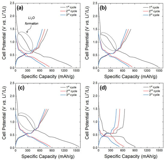
Figure 9.
Charge and discharge curves for the initial three cycles at a rate of 50 mA/g: core-shell anodes anodized at (a) 6, (b) 8, and (c) 10 V. (d) Sn rod anode.
The charge/discharge capacities and coulombic efficiencies of the first three cycles are summarized in Table 2. The initial discharge capacities of the core-shell anodes anodized at 6, 8, and 10 V were 796, 803, and 808 mAh/g, respectively, significantly higher than that of the Sn rod anode (645 mAh/g). However, the first-cycle coulombic efficiencies of the core–shell anodes were relatively low for all three samples (ranging from 52% to 57%), lower than that of the Sn rod anode (71%), and showed a decreasing trend with increasing anodization voltage. This reduction in the coulombic efficiency is likely due to an increase in irreversible capacity caused by Li2O formation during the initial charge. However, the core-shell anodes exhibited a smaller discharge capacity fade after the first cycle than the Sn rod anode, leading to a more pronounced capacity difference between the core-shell and the Sn rod anode over repeated cycles. Notably, the coulombic efficiencies of the core-shell anodes improved to approximately 87–89% after the first cycle, significantly exceeding that of the Sn rod anode (~83%).

Table 2.
Specific charge/discharge capacity and coulombic efficiency for the initial three cycles at a rate of 50 mA/g: core-shell anodes anodized at (a) 6, (b) 8, (c) 10 V; (d) Sn rod anode.
Figure 10a shows the discharge capacity retentions and coulombic efficiencies of the samples cycled at a current density of 100 mA/g after the initial three cycles. The Sn rod anode deteriorated rapidly from the beginning of cycling, with capacity retention decreasing to approximately 30% after the 10th cycle. In contrast, the core-shell anodes showed a more gradual decline, with higher capacity retention observed at increased anodization voltage. It is speculated that, even with the use of a 1-D Sn rod structure, the pure Sn metal anode struggled to effectively accommodate volume changes. This limitation is attributed to the inability of surrounding conductive additives, binders, and electrode pores to absorb the volume expansion, leading to the Sn rods delamination. However, it is believed that by forming a porous oxide layer on the surface of the Sn rod, the active material itself was able to effectively accommodate the volume change, reducing active material delamination and improving cycle life.
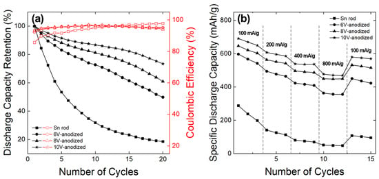
Figure 10.
(a) Variations in discharge capacity retention and Coulombic efficiency of the samples with charge-discharge cycle at a rate of 100 mA/g, following the initial three cycles and (b) their rate capability.
Notably, higher capacity retention was observed in Sn-oxide layers formed at higher anodization voltages, which were characterized by larger pore diameters and thinner pore walls (Figure 5h). This strongly suggests that porous structures with open pores provide greater stress-relief effects compared with smaller pore diameters and thicker pore wall structures. Quantitatively, a porous Sn-oxide layer with surface pore diameters exceeding 50 nm—corresponding to films anodized at voltages above 8 V—is required to significantly enhance cycle life performance. Despite the notable improvement in capacity retention compared to the Sn rod anode, the still-low capacity retention rate (~73% at the 20th cycle) indicates that further optimization is needed for practical applications. Figure 10b demonstrates the rate capabilities of the samples. Severe capacity degradation in the Sn rod anode made it difficult to assess their rate performance accurately. The core-shell anodes anodized at 6, 8, and 10 V, which exhibited reduced capacity fade, achieved discharge capacities of 356, 449, and 469 mAh/g, respectively, at a high discharge rate of 800 mA/g, corresponding to capacity retention of 60%, 69%, and 68%. If capacity degradation from cycling is excluded—focusing solely on kinetic performance—higher capacity retention can be expected. This excellent rate performance is most likely attributed to the open structure and large surface area of the mesoporous Sn-oxide, which facilitates efficient Li+ transport and rapid surface reactions during discharge.
Figure 11 shows the surface morphology of the Sn rod anode and the core–shell anode anodized at 10 V, both before and after cycling. For the Sn rod anode, distinct rod structures were clearly observed on the as-prepared anode surface (Figure 11a). However, after cycling, the rod-like morphology completely disappeared, and the surface was dominated by small or agglomerated particles (Figure 11b). This structural deterioration is ascribed to rod crushing, detachment, and shape change due to severe volume changes during charge-discharge cycles. These findings suggest that the relatively low cycle stability of Sn rod anodes is primarily due to physical damage of the active material. In contrast, the core-shell anode anodized at 10 V retained its initial anode structure, with rods still observed after 20 cycles (Figure 11c,d). The porous Sn-oxide layer on the rod surface also remained well-preserved (inset figures). This indicates that the superior cycling performance of the anodized Sn rod is due to the porous Sn-oxide layer, which effectively accommodates volume changes, thereby minimizing physical damage and enhancing structural stability throughout charge-discharge cycles.
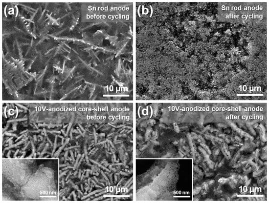
Figure 11.
Surface morphology of the anodes: Sn rod anode (a) before and (b) after cycling. Core-shell anode anodized at 10 V (c) before and (d) after cycling. The inset figures in (c,d) are magnified images.
4. Conclusions
In this study, core–shell structures consisting of a Sn rod core and a mesoporous Sn-oxide shell were fabricated using a facile electrochemical method and evaluated as anode materials for lithium-ion batteries (LIBs). Comprehensive results highlighted the influence of processing parameters on the resulting morphology and electrochemical performance of these materials. The experimental findings are summarized as follows:
- Dendritic Sn, composed of primary and secondary rods, was successfully fabricated via single electrodeposition. Under constant-current conditions, the diameter of the secondary Sn rods increased linearly with rising current density, but at current densities above 4 A/cm2 and a deposition time of 10 s, agglomeration between the secondary rods was observed. In contrast, under constant-voltage conditions, highly uniform secondary rods were formed without agglomeration, even when a larger amount of Sn was deposited than under constant-current conditions, where the aggregated structure appeared.
- The Sn micro rods were anodized to form core-shell structures, where the surface of the Sn rods was covered with mesoporous Sn-oxide. A uniformly distributed porous Sn-oxide layer was successfully formed across the entire surface at anodization above 6 V. As the anodization voltage increased, the pore size increased, while pore wall thickness decreased.
- The core-shell anodes were evaluated for LIB application. During the first cathodic scan (lithiation) of the cyclic voltammetry experiment, Li2O formation was observed at approximately 0.5–0.8 V vs. Li+/Li. This Li2O was partially decomposed in the subsequent anodic scan, contributing to the reversible capacity. At higher anodization voltages, the Li2O-related signal became more pronounced, indicating an increased Li2O contribution to the reversible capacity.
- The initial charge-discharge tests of the core-shell anodes exhibited specific capacities comparable to or exceeding that of the Sn rod anode. Higher anodization voltages resulted in higher specific capacities. The core-shell anodes also demonstrated slower capacity fade than the Sn rod anode, with higher discharge capacity retention at increased anodization voltage. Despite these promising results, significant initial irreversible capacity loss and cycle degradation remain challenges that must be addressed for commercial viability.
Author Contributions
Data curation, W.-J.L. and Y.-J.M.; formal analysis, W.-J.L.; funding acquisition, H.-C.S.; investigation, W.-J.L. and Y.-J.M.; methodology, W.-J.L.; supervision, H.-C.S.; validation, W.-J.L., Y.-J.M. and H.-C.S.; writing—original draft, W.-J.L.; writing—review & editing, H.-C.S. All authors have read and agreed to the published version of the manuscript.
Funding
This work was supported by the National Research Foundation of the Ministry of Science and ICT (RS-2025-00512708) and by the Korea Institute of Energy Technology Evaluation and Planning (KETEP) and the MOTIE of the Republic of Korea (No. 20224000000400).
Institutional Review Board Statement
Not applicable.
Informed Consent Statement
Not applicable.
Data Availability Statement
The data that support the findings of this study are available from the corresponding author upon request.
Conflicts of Interest
The authors declare no conflicts of interest.
References
- Ruiz, V.; Pfrang, A.; Kriston, A.; Omar, N.; Van den Bossche, P.; Boon-Brett, L. A Review of International Abuse Testing Standards and Regulations for Lithium-Ion Batteries in Electric and Hybrid Electric Vehicles. Renew. Sustain. Energy Rev. 2018, 81, 1427–1452. [Google Scholar] [CrossRef]
- Peters, J.F.; Baumann, M.; Zimmermann, B.; Braun, J.; Weil, M. The environmental impact of Li-ion batteries and the role of key parameters–a review. Renew. Sustain. Energy Rev. 2017, 67, 491–506. [Google Scholar] [CrossRef]
- Ding, Y.; Cano, Z.P.; Yu, A.; Lu, J.; Chen, Z. Automotive Li-ion batteries: Current status and future perspectives. Electrochem. Energy Rev. 2019, 2, 1–28. [Google Scholar] [CrossRef]
- Jaguemont, J.; Boulon, L.; Dubé, Y. A comprehensive review of lithium-ion batteries used in hybrid and electric vehicles at cold temperatures. Appl. Energy 2016, 164, 99–114. [Google Scholar] [CrossRef]
- Diouf, B.; Pode, R. Potential of lithium-ion batteries in renewable energy. Renew. Energy 2015, 76, 375–380. [Google Scholar] [CrossRef]
- Deng, J.; Bae, C.; Denlinger, A.; Miller, T. Electric vehicles batteries: Requirements and challenges. Joule 2020, 4, 511–515. [Google Scholar] [CrossRef]
- Brunklaus, G.; Lennarts, P.; Winter, M. Metal electrodes for next-generation rechargeable batteries. Nat. Rev. Electr. Eng. 2024, 1, 79–92. [Google Scholar] [CrossRef]
- Shen, X.; Zhang, X.Q.; Ding, F.; Huang, J.Q.; Xu, R.; Chen, X.; Zhang, Q. Advanced electrode materials in lithium batteries: Retrospect and prospect. Energy Mater. Adv. 2021, 4, 1–15. [Google Scholar] [CrossRef]
- Mou, H.; Xiao, W.; Miao, C.; Li, R.; Yu, L. Tin and tin compound materials as anodes in lithium-ion and sodium-ion batteries: A review. Front. Chem. 2020, 8, 141. [Google Scholar] [CrossRef]
- Liang, S.; Cheng, Y.J.; Zhu, J.; Xia, Y.; Müller-Buschbaum, P. A chronicle review of nonsilicon (Sn, Sb, Ge)-based lithium/sodium-ion battery alloying anodes. Small Methods 2020, 4, 2000218. [Google Scholar] [CrossRef]
- Wang, R.; Sun, S.; Xu, C.; Cai, J.; Gou, H.; Zhang, X.; Wang, G. The interface engineering and structure design of an alloying-type metal foil anode for lithium ion batteries: A review. Mater. Horiz. 2024, 11, 903–922. [Google Scholar] [CrossRef] [PubMed]
- Liu, W.; Zhi, H.; Yu, X. Recent progress in phosphorus-based anode materials for lithium/sodium ion batteries. Energy Storage Mater. 2019, 16, 290–322. [Google Scholar] [CrossRef]
- Jin, Y.; Zhu, B.; Lu, Z.; Liu, N.; Zhu, J. Challenges and recent progress in the development of Si anodes for lithium-ion battery. Adv. Energy Mater. 2017, 7, 1700715. [Google Scholar] [CrossRef]
- Ma, D.; Cao, Z.; Hu, A. Si-based anode materials for Li-ion batteries: A mini review. Nano-Micro Lett. 2014, 6, 347–358. [Google Scholar] [CrossRef]
- Wang, G.; Aubin, M.; Mehta, A.; Tian, H.; Chang, J.; Kushima, A.; Yang, Y. Stabilization of Sn anode through structural reconstruction of a Cu–Sn intermetallic coating layer. Adv. Mater. 2020, 32, 2003684. [Google Scholar] [CrossRef]
- Tang, Y.; Bi, C.; Zhang, D.; Hou, G.; Cao, H.; Wu, L.; Wu, Q. Three-dimensional ordered macroporous Cu/Sn anode for high rate and long cycle life lithium-ion batteries. Microporous Mesoporous Mater. 2019, 274, 76–82. [Google Scholar] [CrossRef]
- Beaulieu, L.Y.; Dahn, J.R. The reaction of lithium with Sn-Mn-C intermetallics prepared by mechanical alloying. J. Electrochem. Soc. 2000, 147, 3237. [Google Scholar] [CrossRef]
- Mao, O.; Dunlap, R.A.; Dahn, J.R. Mechanically alloyed Sn-Fe (-C) powders as anode materials for Li-ion batteries: I. The Sn2Fe-C system. J. Electrochem. Soc. 1999, 146, 405. [Google Scholar] [CrossRef]
- Wang, B.; Luo, B.; Li, X.; Zhi, L. The dimensionality of Sn anodes in Li-ion batteries. Mater. Today 2012, 15, 544–552. [Google Scholar] [CrossRef]
- Chao, S.C.; Yen, Y.C.; Song, Y.F.; Chen, Y.M.; Wu, H.C.; Wu, N.L. A study on the interior microstructures of working Sn particle electrode of Li-ion batteries by in situ X-ray transmission microscopy. Electrochem. Commun. 2010, 12, 234–237. [Google Scholar] [CrossRef]
- Park, J.; Eom, J.; Kwon, H. Fabrication of Sn–C composite electrodes by electrodeposition and their cycle performance for Li-ion batteries. Electrochem. Commun. 2009, 11, 596–598. [Google Scholar] [CrossRef]
- Pourfarzad, H.; Shabani-Nooshabadi, M.; Ganjali, M.R. High lithium anodic performance of reduced Sn particles on Co metal-organic frameworks for lithium-ion batteries with a long-cycle life. Compos. Part B Eng. 2020, 193, 108008. [Google Scholar] [CrossRef]
- Shi, H.; Fang, Z.; Zhang, X.; Li, F.; Tang, Y.; Zhou, Y.; Yu, G. Double-network nanostructured hydrogel-derived ultrafine Sn–Fe alloy in three-dimensional carbon framework for enhanced lithium storage. Nano Lett. 2018, 18, 3193–3198. [Google Scholar] [CrossRef]
- Polat, D.B.; Lu, J.; Abouimrane, A.; Keles, O.; Amine, K. Nanocolumnar structured porous Cu-Sn thin film as anode material for lithium-ion batteries. ACS Appl. Mater. Interfaces 2014, 6, 10877–10885. [Google Scholar] [CrossRef]
- Lan, X.; Xiong, X.; Liu, J.; Yuan, B.; Hu, R.; Zhu, M. Insight into reversible conversion reactions in SnO2-based anodes for lithium storage: A Review. Small 2022, 18, 2201110. [Google Scholar] [CrossRef]
- Ma, G.; Yang, W.; Xu, C.; Che, S.; Li, Y.; Liu, H.; Chen, N.; Zhang, G.; Liu, H.; Wu, N.; et al. Nitrogen-doped porous carbon embedded Sn/SnO nanoparticles as high-performance lithium-ion battery anode. Electrochim. Acta 2022, 428, 140898. [Google Scholar] [CrossRef]
- Hameed, M.U.; Dar, S.U.; Ali, S.; Liu, S.; Akram, R.; Wu, Z.; Butler, I.S. Facile synthesis of low-dimensional SnO2 nanostructures: An investigation of their performance and mechanism of action as anode materials for lithium-ion batteries. Phys. E Low-Dimens. Syst. Nanostruct. 2017, 91, 119–127. [Google Scholar] [CrossRef]
- Das, B.; Reddy, M.V.; Chowdari, B.V.R. SnO and SnO·CoO nanocomposite as high capacity anode materials for lithium ion batteries. Mater. Res. Bull. 2016, 74, 291–298. [Google Scholar] [CrossRef]
- Shin, J.H.; Song, J.Y. Electrochemical properties of Sn-decorated SnO nanobranches as an anode of Li-ion battery. Nano Converg. 2016, 3, 9. [Google Scholar] [CrossRef][Green Version]
- Chen, Y.; Zhang, F.; Tian, Q.; Zhang, W. Facile preparation of one-dimensional hollow tin dioxide@carbon nanocomposite for lithium-ion battery anode. J. Electroanal. Chem. 2020, 861, 113943. [Google Scholar] [CrossRef]
- Cheong, J.Y.; Chang, J.H.; Kim, C.; Lee, J.; Shim, Y.S.; Yoo, S.J.; Kim, I.D. Unveiling the origin of superior electrochemical performance in polycrystalline dense SnO2 nanospheres as anodes for lithium-ion batteries. ACS Appl. Energy Mater. 2019, 2, 2004–2012. [Google Scholar] [CrossRef]
- Zhu, Y.; Guo, H.; Zhai, H.; Cao, C. Microwave-assisted and gram-scale synthesis of ultrathin SnO2 nanosheets with enhanced lithium storage properties. ACS Appl. Mater. Interfaces 2015, 7, 2745–2753. [Google Scholar] [CrossRef] [PubMed]
- Wang, C.; Li, Y.; Chui, Y.S.; Wu, Q.H.; Chen, X.; Zhang, W. Three-dimensional Sn–graphene anode for high-performance lithium-ion batteries. Nanoscale 2013, 5, 10599–10604. [Google Scholar] [CrossRef]
- Cao, L.; Liu, J.; Xu, S.; Xia, Y.; Huang, W.; Li, Z. Inherent superhydrophobicity of Sn/SnOX films prepared by surface self-passivation of electrodeposited porous dendritic Sn. Mater. Res. Bull. 2013, 48, 4804–4810. [Google Scholar] [CrossRef]
- Jeun, J.-H.; Kin, W.-S.; Hong, S.-H. Electrophoretic deposition of carbon nanoparticles on dendritic Sn foams fabricated by electrodeposition. Mater. Lett. 2013, 112, 109–112. [Google Scholar] [CrossRef]
- Lee, J.W.; Park, S.J.; Choi, W.S.; Shin, H.C. Well-defined meso- to macro-porous film of tin oxides formed by an anodization process. Electrochim. Acta 2011, 56, 5919–5925. [Google Scholar] [CrossRef]
- Gurgul, M.; Gawlak, K.; Knapik, A.; Kozieł, M.; Zaraska, L. The effect of electrolyte temperature on the growth morphology and properties of porous anodic tin oxide films. J. Electroanal. Chem. 2023, 932, 117246. [Google Scholar] [CrossRef]
- Lu, C.; Wang, J.; Meng, D.; Wang, D.; Wang, Y.; Zhu, Z. Tunable synthesis of nanoporous tin oxide structures on metallic tin by one-step electrochemical anodization. J. Alloys Compd. 2016, 685, 670–679. [Google Scholar] [CrossRef]
- Zaraska, L.; Gawlak, K.; Gurgul, M.; Chlebda, D.K.; Socha, R.P.; Sulka, G.D. Controlled synthesis of nanoporous tin oxide layers with various pore diameters and their photoelectrochemical properties. Electrochim. Acta 2017, 254, 238–245. [Google Scholar] [CrossRef]
- Li, J.; Li, H.; Wang, Z.; Huang, X.; Chen, L. The interaction between SnO anode and electrolytes. J. Power Sources 1999, 81, 346–351. [Google Scholar] [CrossRef]
- Das, B.; Reddy, M.V.; Subba Rao, G.V.; Chowdari, B.V.R. Nano-composites SnO (VOX) as anodes for lithium ion batteries. J. Solid State Electrochem. 2011, 15, 259–268. [Google Scholar] [CrossRef]
- Yin, L.; Chai, S.; Wang, F.; Huang, J.; Li, J.; Liu, C.; Kong, X. Ultrafine SnO2 nanoparticles as a high performance anode material for lithium ion battery. Ceram. Int. 2016, 42, 9433–9437. [Google Scholar] [CrossRef]
- Lin, J.; Peng, Z.; Xiang, C.; Ruan, G.; Yan, Z.; Natelson, D.; Tour, J.M. Graphene nanoribbon and nanostructured SnO2 composite anodes for lithium ion batteries. ACS Nano 2013, 7, 6001–6006. [Google Scholar] [CrossRef]
- Mohamedi, M.; Lee, S.J.; Takahashi, D.; Nishizawa, M.; Itoh, T.; Uchida, I. Amorphous tin oxide films: Preparation and characterization as an anode active material for lithium ion batteries. Electrochim. Acta 2001, 46, 1161–1168. [Google Scholar] [CrossRef]
- Deng, J.; Yan, C.; Yang, L.; Baunack, S.; Oswald, S.; Wendrock, H.; Schmidt, O.G. Sandwich-stacked SnO2/Cu hybrid nanosheets as multichannel anodes for lithium ion batteries. ACS Nano 2013, 7, 6948–6954. [Google Scholar] [CrossRef]
- Winter, M.; Besenhard, J.O. Electrochemical lithiation of tin and tin-based intermetallics and composites. Electrochim. Acta 1999, 45, 31–50. [Google Scholar] [CrossRef]
Disclaimer/Publisher’s Note: The statements, opinions and data contained in all publications are solely those of the individual author(s) and contributor(s) and not of MDPI and/or the editor(s). MDPI and/or the editor(s) disclaim responsibility for any injury to people or property resulting from any ideas, methods, instructions or products referred to in the content. |
© 2025 by the authors. Licensee MDPI, Basel, Switzerland. This article is an open access article distributed under the terms and conditions of the Creative Commons Attribution (CC BY) license (https://creativecommons.org/licenses/by/4.0/).