Article

Investigation of a New Vibration-Absorbing Roller Cage Shoe with a Magnetorheological Damper in Mine Hoisting Systems

School of Mechanical Engineering, Nantong University, Nantong 226019, China
*
Author to whom correspondence should be addressed.
Appl. Sci. 2023, 13(22), 12506; https://doi.org/10.3390/app132212506
Submission received: 19 September 2023 / Revised: 13 November 2023 / Accepted: 15 November 2023 / Published: 20 November 2023
(This article belongs to the Section Mechanical Engineering)

Abstract

:
In the mine hoisting system, rigid guide failures and the influence of internal and external airflow intensify vessel transverse vibration, heightening demands on operational safety and equipment reliability. This paper focuses on integrating magnetorheological dampers and disc springs as the roller cage shoe buffer for vibration control, resulting in an innovative buffer device. The structure and magnetic circuit were meticulously designed. Using Maxwell simulation, we analyzed the impact of magnetic circuit parameters—specifically the damping gap and core radius—on the magnetorheological damper. We optimized these parameters through orthogonal testing to enhance damping and vibration reduction. This led to a notable 58% increase in the damper output force. A virtual prototype of the lifting system under actual working conditions was established. A simulation analysis verified the vibration-damping performance of the optimized roller cage shoe. The results indicate that the new roller cage shoes effectively inhibit transverse vibration, surpassing traditional roller cage shoe performance. This is scientifically and practically significant for ensuring safe cage shoe lifting system operation. This paper can provide a crucial theoretical basis for the design of roller cage shoes in ultra-deep mine lifting systems.

1. Introduction

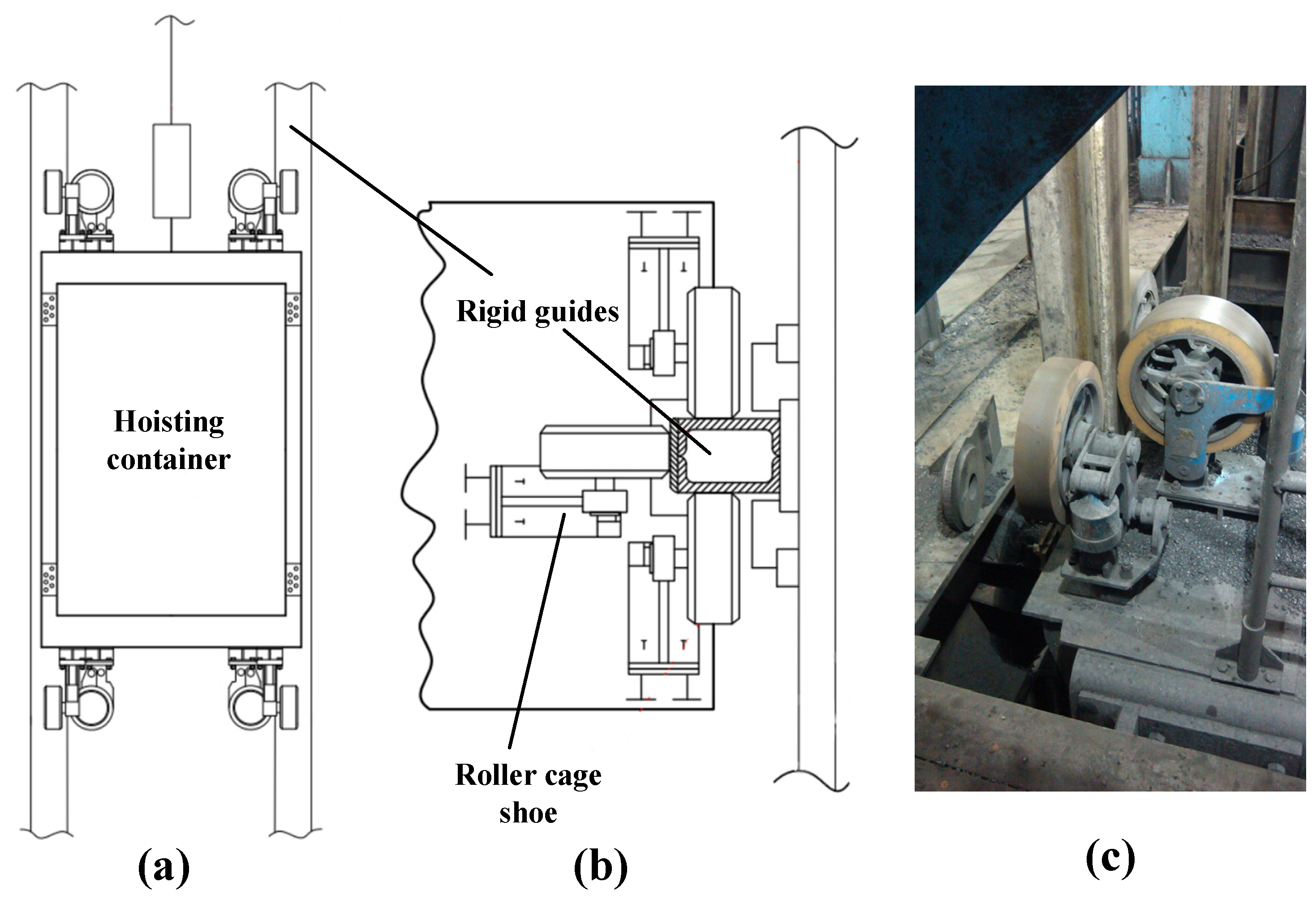
The mine hoisting system, whose safety and stability directly influence both productivity and personnel safety, plays a pivotal role in mine production. As depicted in Figure 1, the core components of the mine hoisting system include the rigid guide, roller cage shoe, and hoisting container. The roller cage shoe is affixed to the hoisting container and moves vertically along the rigid guide. During the operation of the mine hoisting system, some factors such as the failure of the rigid guide and disturbances from internal and external airflow can lead to adverse working conditions, and thereby intensify complex collisions between the rigid cage shoe and rigid guide, subsequently exacerbating the corresponding deformation damage. Consequently, a new roller cage shoe equipped with features that can absorb the vibration of the hoisting container should be proposed.
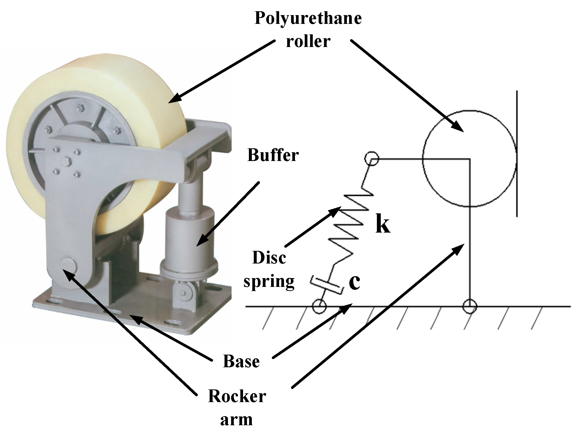
Conventional lifting system vessels are usually equipped with four sets of roller cage shoes which play the roles of guiding and buffering, and each set consists of three pieces. They are distributed and fixed at both the left and right sides and both the upper and lower ends of the container. The traditional elastic roller cage shoe structure, as illustrated in Figure 2, comprises four main components, including the disc springs, base, rocker arm, and polyurethane roller. The roller is connected to the rocker arm via the drive shaft, which can make the rocker’s arm pivot around the base and simultaneously compress the disc springs. Therefore, horizontal buffering forces will be generated when lateral impacts are imposed on the roller in the lifting process. Due to the existence of the disc springs and its friction damping, the horizontal vibration of the container can be suppressed to a certain extent. However, this type of guide device lacks the function of damping adjustment with which the horizontal vibration of the container can be greatly reduced. The present paper is devoted to designing a new roller cage shoe with a magnetorheological damper to realize a reduction in the horizontal vibration of the mine hoisting container.
In recent years, some researchers have investigated reductions in transverse vibration in mine hoisting systems. Cao et al. [1] studied the lateral response of a moving hoisting transporter in a cable-guided system. They developed a nonlinear dynamic model and compared it with simulation results. The analyses included vibration responses under different initial conditions, and some suggestions were provided to reduce vibration and improve the system stability. Deng et al. [2] introduced a semi-active control scheme to address horizontal vibrations in mine hoisting systems by employing a fuzzy skyhook damping strategy in tandem with magnetorheological fluid dampers. In the present mine hoisting system, there is a noticeable emphasis on investigating the vibration characteristics and control of mine hoisting. Ma et al. [3] based a constant deceleration compensation device on the original brakes, and it was verified through experiments and simulations that the device can realize constant deceleration in a very short time. However, there has been relatively limited exploration of vibration control devices. The majority of conventional roller cage shoes rely on passive vibration-damping methods, such as disc springs and hydraulics [4]. The present guide device unfortunately exhibits drawbacks such as a slow response, a limited damping capacity, and susceptibility to structural failure. Given the system’s vulnerability to both internal and external disturbances, it is prone to generating substantial vibration impacts. In more severe instances, it can culminate in rope breakage and catastrophic falling accidents.
In the elevator hoisting system, which is similar to the mine hoisting system, the study of transverse vibration and vibration control devices is more in-depth. Zhang et al. [5] optimized the parameters of a guide shoe to suppress car vibration by studying the relationship between the deformation amount of the guide shoe and the restoring force. Han et al. [6] studied the mechanical model of the elevator guiding system and obtained the relationship between the load and deformation of the guide shoe. In elevator hoisting systems, the investigation into vibration-damping mechanisms primarily centers on hydraulic floating sky wheels, electromagnetic active guide shoes, hydraulic active guide shoes, servomotor active guide shoes, and magnetic levitation guide shoes [7].
The roller cage shoe includes an active guide shoe and a passive guide shoe. Passive roller cage shoes primarily rely on a spring damping system to gradually diminish car vibrations. While effective to an extent, they have limitations in swiftly suppressing vibrations and enhancing the comfort of the lift ride [8]. On the other hand, active roller cage shoes designed for vibration control are intricate, expensive, and demand a continuous supply of external energy. In comparison, semi-active control systems offer damping effects akin to active control but can modify their damping characteristics with minimal energy input, resulting in lower costs and enhanced stability. Among semi-active control devices, MRDs stand out as being highly promising due to their outstanding attributes.
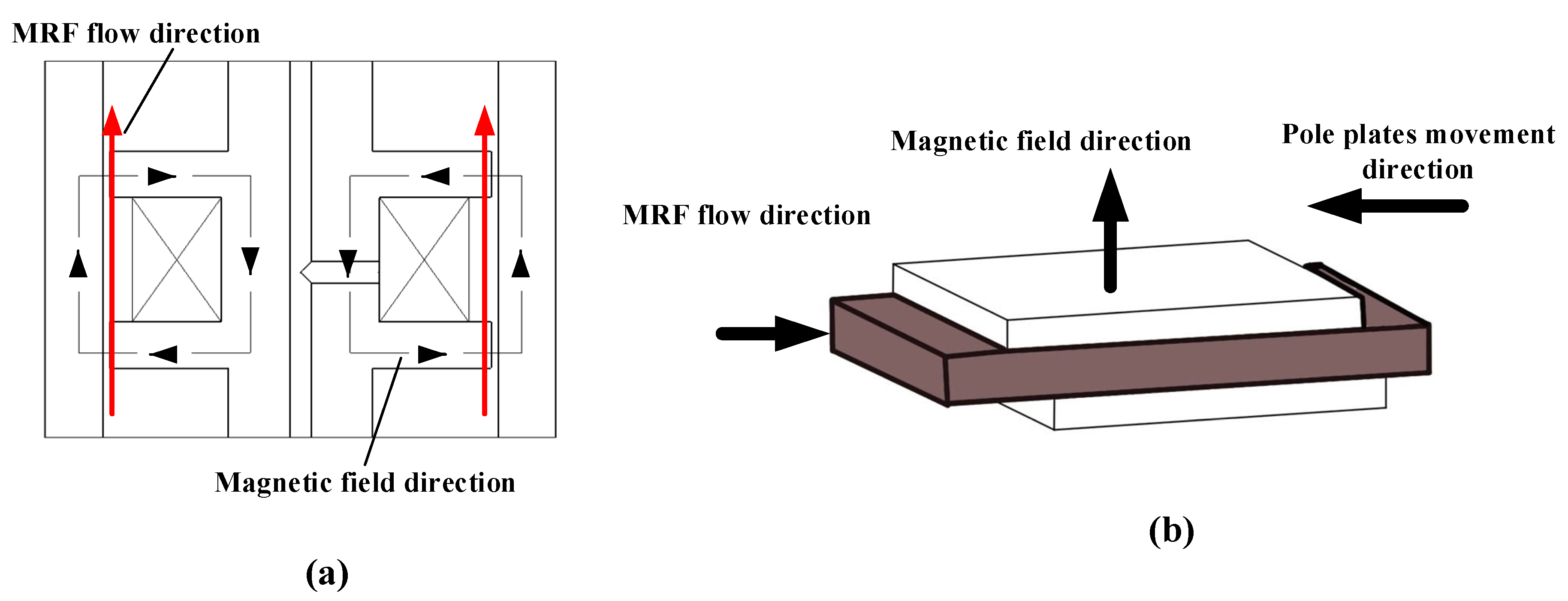
The magnetorheological damper (MRD) utilizes magnetorheological fluid (MRF) to absorb shocks. By adjusting the current in the excitation coil, different magnetic field forces are achieved. This causes the fluid’s rheological properties to change, generating resistance to movement and effectively damping vibrations [9]. As a highly effective semi-active damper, it can be extensively used in transportation, structural seismic applications, and other fields. Bang-Hyun Jo et al. [10] explored the feasibility of employing magnetorheological group dampers in an airplane landing-gear system to diminish unintended shocks and vibrations during the landing and taxiing phases. Kawase et al. [11] conducted an experimental validation of the seismic performance of an elevator equipped with MRF dampers during an earthquake. This system’s effectiveness was verified through numerical simulations in elevator applications. The MRD principle is also widely utilized for vibration damping in elevator hoisting systems. Li et al. [12] developed an elevator MRD based on a permanent magnetic field, investigating factors like the magnetic field strength, distribution, descent speed, deceleration time, and distance. The results demonstrated that the eddy currents induced by the permanent magnetic field effectively achieved elevator deceleration. Zhang et al. [13] introduced a variable-domain fuzzy control method for semi-active roller cage shoes equipped with magnetorheological dampers; the elevator experiments conclusively demonstrated that this controller proficiently mitigates horizontal vibrations. In summary, the controller proves highly effective in suppressing horizontal vibrations, markedly enhancing the ride experience in high-speed elevators. Santo et al. [14] and colleagues investigated the horizontal response of vertical transportation systems with nonlinearities under guideway deformation excitation. They put forward a strategy for controlling the dynamic horizontal behavior of a three-degree-of-freedom model using a controllable MRD, which demonstrated an effective reduction in vertical transport vibrations. In the mine hoisting system, Wu et al. [15] introduced a novel type of MRD vibrating screen damper; experimental evaluations demonstrated a superior vibration-damping performance. Additionally, Yao et al. [16] proposed a tension equalizer based on MRDs, and its potential for vibration reduction was confirmed through numerical simulations.
The literature above highlights a predominant focus on analyzing the vibration characteristics and control strategies in mine hoisting. However, it is evident that there is a lack of reliable vibration-damping devices and proven-effective methods for vibration reduction in mine hoisting systems. The field still largely adheres to traditional design theories. Effectively mitigating vibration in mine hoisting systems remains a critical concern for ensuring both mine production safety and efficiency.
This paper drew from the use of the MRF rheological principle of vibration damping in the mine hoisting system and designed a new type of roller cage shoe by applying the excellent characteristics of MRF dampers. MRDs and disc springs were used as the buffers of the roller cage shoe for vibration reduction, and the performance of vibration reduction was optimized and verified through simulations. This study can provide new ideas for the stability design of ultra-deep mine hoisting systems. This new roller cage shoe offers advantages such as low power consumption, a compact size, a controllable damping force, a rapid response (in milliseconds), a simple structure, excellent temperature stability, and resilience to impurities.
The main structure of the content of the present paper is (1) Section 2: the structural design of the cushioning cage shoe based on MRDs; (2) Section 3: the influence of structural parameters on the performance of the damper; (3) Section 4: the simulation and analysis of the virtual prototype of the cage shoe cushion; and (4) Section 5: the conclusion.

2. Theoretical Analysis and Design of the MRD-Based Roller Cage Shoe

2.1. Basic Structure of MRD-Based Roller Cage Shoes

This paper suggests employing a combination of MRDs and disc springs in series to create the cage shoe buffer structure, as an alternative to the conventional cage shoe buffer for semi-active vibration damping. MRDs are vibration dampers with smart material MRF as the force-transmitting medium. Adjusting the current in the excitation coil can obtain different strengths of the magnetic field. When MRF is under the action of the external magnetic field, the rheological properties of the MRF will be changed to produce resistance to movement; as a result, the energy of the movement will be consumed. In response to this, the purpose of vibration damping, which has the advantages of a continuously adjustable damping force, large output force, and fast response speed, can be achieved.
In this paper, the design of the MRD-based roller cage shoe buffer damper is illustrated in Figure 3. During operation, the MRD is situated in the upper section of the cage shoe buffer, while the disc spring assembly is positioned in the lower part. The MRD primarily consists of a piston rod, cylinder barrel, and end caps on both sides. The damper adopts a single-cylinder double-outlet rod structure. One end of the piston is securely fastened to the swing arm of the roller cage shoe, providing guidance and support. The opposite end is linked in series with the disc spring via a damping baffle plate, ensuring ample space for the piston rod’s movement and facilitating the transmission of damping force. The piston rod has a groove where the coil is tightly wound. It also contains a blind hole structure serving as a lead channel. The two end wires connect to the external program-controlled power supply through this channel. The end caps on both sides connect to the cylinder barrel, creating the MRF chamber. To prevent any MRF leakage, a sealing assembly is in place between the piston rod and cylinder barrel. The topside cover features a liquid-filling port, while the bottom cover is securely affixed with a disk spring sleeve. The guide bar for the disc spring is bolted to the base, allowing the disc spring set to move axially along the guide bar. This arrangement serves as supplementary vibration damping during the buffer’s regular operation.

2.2. Mechanical Model of MRD-Based Roller Cage Shoes

2.2.1. Rheological Mechanical Model of MRDs

Figure 4a illustrates a simplified model of the magnetic circuit within the MRD. The magnetorheological fluid damping buffer employs a shear valve mode, with the magnetic field’s direction perpendicular to the MRF movement. This configuration creates a ring-shaped damping channel between the sides of the damper’s piston rod and the inner wall of the cylinder. When the piston rod experiences force from the roller, it causes a change in the volume of the upper and lower fluid chambers due to axial movement. This prompts MRF to flow from the lower chamber into the upper chamber through the damping channel. Upon energizing the coil, electromagnetic induction principles come into play. This results in the generation of magnetic flux density across the resistive gap between the inner damping cylinder and the outer piston head. The applied magnetic field induces the magnetorheological effect, creating resistance to motion. This, in turn, hinders the movement of the piston, leading to effective vibration damping.
The shear valve mode is a hybrid mode that combines shear and valve characteristics. In this mode, there is parallel relative motion between the upper and lower pole plates of the MRD. Simultaneously, the MRF in the gap between the pole plates flows in a direction parallel to the plates. At this juncture, the applied magnetic field’s direction is perpendicular to both the motion of the pole plates and the flow of the MRF [17], as depicted in Figure 4b. The damping force of the MRD in this mode is the combined result of both the shear and valve components. Therefore, the damping force of the MRD can be mathematically represented as
F 1 = 12 η L v π D h 3 A p 2 + 3 l h τ y A p
F 2 = η b L h v 2 b L τ y
where F 1 is the damping force provided in valve mode and F 2 is the damping force provided in shear mode; η is the zero-field viscosity of the MRF; L is the effective length of the piston; A p is the area of the piston; h is the damping channel gap between the piston and the cylinder; D is the outer diameter of the piston; τ y is the shear yield strength of the MRF; and v is the speed of movement of the piston relative to the cylinder.
Superimposing the two equations gives the damping force in the shear valve mode as
F = F η + F τ = ( 12 η L A p 2 π D h 3 + η b L h ) v + ( 3 L A p h 2 b L ) τ y
where F η is the velocity-dependent viscous damping force; F τ is the Coulomb damping force that varies with the magnetic field. Because of the small width of the damping channel, the damping force generated by the MRF during flow is much smaller than that due to shear, so in the preliminary design, the damping force in the mixed mode can be approximated using the following equation:
F = F η + F τ = 12 η L A p 2 π D h 3 v + 3 L τ y A p h sgn v
The dynamic tunability factor can be approximated based on the ratio of the Coulomb force to the viscous force:
λ = F τ F η = τ y D h 2 4 η A p v
The MRF used in the MRD designed in this paper is MRF-J25T, which has a large shear yield strength and good settling stability. The basic parameters are shown in Table 1.
The relationship between the shear yield stress ( τ ) and the magnetic field strength, B, is shown in Figure 5, which shows nonlinearity. By curve fitting, the τ–B relation function of this MRF can be obtained as
τ y = a 4 B 4 + a 3 B 3 + a 2 B 2 + a 1 B + a 0
where a4 = 1085.56 kPa/T4, a3 = −2046.42 kPa/T2, a2 = 1102.102 kPa/T2, a1 = −37.6018 kPa/T, a0 = 1.49834 kPa.

2.2.2. Calculation of Disc Spring Stiffness

Disc springs, serving as prevalent non-linear vibration-damping elements, possess the capability to bear a substantial load with minor deformation. Disc springs in use often need more than one disc spring in a certain combination, mainly in the forms of pairs, stacks, and their composite form. For the design of the disc spring structure in the magnetorheological damping buffer proposed in this paper, considering the working environment of the disc spring, the structure of the space, and size requirements, a series of disc springs with the material of 60Si2MnA was selected. The selected disc spring parameters are shown in Table 2.
Currently, the load capacity, F , and stiffness, F , of disc springs are usually calculated using the approximation provided by the Almen–Laszlo formula in the national standard. This method was developed by J. O. Almen and Laszlo [18] in 1936, based on the assumption of a curved beam, as a formula for calculating the characteristics of a butterfly spring with a uniform cross-section. After many years of practical testing, the method has proved to be relatively stable and reliable in general engineering applications and is therefore widely used in several international and industry standards. The A-L formula ignores the effects of frictional radial stress, friction, contact nonlinearity, etc. The relationship between load and deformation can be calculated according to the geometrical parameters and material properties of the disc-shaped single spring. The advantage of this formula is that it is simple and easy to use, and it is suitable for general engineering applications with small deformations, simple structures, and low accuracy requirements. Therefore, this formula is chosen for calculation based on the operation of the MRD.
F = 4 E 1 μ 2 t 3 K 1 D 2 K 4 2 { K 4 2 [ ( h 0 t ) 2 3 h 0 t f t + 3 2 ( f t ) 2 ] + 1 }
F = 4 E 1 μ 2 t 4 K 1 D 2 K 4 2 f t [ K 4 2 ( h 0 t f t ) ( h 0 t f 2 t ) + 1 ]
where
K 1 = 1 π [ ( C 1 ) / C ] 2 ( C + 1 ) / ( C 1 ) 2 / ln 2
K 4 = C 1 2 + ( C 1 2 ) 2 + C 2
C = D d
C 1 = ( t / t ) 2 [ ( 1 / 4 ) ( H 0 / t ) t / t + 3 / 4 ] [ ( 5 / 8 ) ( H 0 / t ) t / t + 3 / 8 ]
C 2 = C 1 ( t / t ) 3 [ 5 32 ( H 0 t 1 ) 2 + 1 ]
where t is the thinning thickness of the disc spring with supporting surfaces. The springs involved in this paper have supporting surfaces, so there are t = t .
The combination of disc springs selected in this paper is in the form of pairs, as shown in Figure 3, which consists of five pairs of disc springs of the same specification. In the absence of friction, there are
F z = F
f z = i f
H i = i H 0
From the above formula, it can be seen that the disc spring pairs are similar to the series form of the spring. The load capacity, F z , of the combined disc spring is equal to the load capacity, F , that each disc spring can provide, and the deflection, f z , is the sum of the deflections, f , of all the constituent disc springs. The stiffness value, F , is 1 i of a single disc spring. For the combined disc spring designed in this paper, the equations describing the relationship between the shape variable and stiffness, as well as the shape variable and load capacity, can be derived as follows:
F = 22.59 8.24 f + 3.17 f 2
F = 29.725 f 12.3591 f 2 + 3.169 f 3

2.3. Design of MRD

2.3.1. Structural Design of MRD

Considering the actual lifting system conditions on the vibration-damping requirements for the buffer cage shoe, the inner diameter of the cylinder of the MRD can be determined using the following formula [19]:
D 1 = 4 F 0 π [ p ] ( 1 λ 2 )
where D 1 is the inner diameter of the cylinder; F 0 is the maximum damping force that the damper needs to withstand; [ p ] is the maximum pressure allowed by the damping, generally taking 2~4 MPa; and λ is the ratio of the diameter of the piston rod to the inner diameter of the cylinder barrel, generally values of 0.4~0.5. The piston rod diameter can be calculated using the formula d = D × λ . Considering the requirements of strength and stiffness of the piston rod at the same time, the strength of the piston rod is calibrated with the following equation:
σ max = F max π d 0 2 / 4 < [ σ ]
where [ σ ] is the allowable stress of the material, σ = σ s n , σ s is the yield strength of the material (20 steel yield strength of 245 MPa), and n is the safety factor (the design requires n 1.2 ); in this paper, n takes the value of 2.
From Equation (3), it can be seen that the Coulomb damping force of the damper is inversely proportional to the damping gap ( h ), and the viscous damping force is inversely proportional to the cubic equation of the damping gap, so the damping gap is a crucial parameter that affects the magnitude of the damping force, and decreasing the value of the damping gap will largely improve the damping force of the damper. And at the same time, when the number of turns of the excitation coils is constant, the small gap will make the magnetic resistance at the gap small and increase the magnetic permeability. However, under the condition that h decreases by the same value, the viscous damping force decreases faster. Therefore, when the damping force is increased by the decreasing h , the power adjustment range is reduced. When determining the damping gap ( h ), the damping force and adjustable range should be considered comprehensively, and usually, h is selected between 0.5 and 2 mm.
The equivalent length of the damping channel signifies the piston’s effective operational length. Any alteration in its value directly impacts both the Coulomb and viscous damping forces. Augmenting the effective working length of the piston amplifies the MRD effect, consequently upscaling the damper’s output damping force. Nonetheless, an excessively extended working length may result in unwieldy dimensions and stroke for the damper. To ensure uniform magnetic field distribution in the MRD and minimize magnetic leakage, it is crucial to maintain a slenderness ratio of 2 h / L 0.2 .

2.3.2. Magnetic Circuit Design of MRD

The magnetic circuit serves as the path for the magnetic lines of force, exerting a significant influence on the magnetic field strength within the damping gap. Once the material for the magnetic circuit is determined, the design and selection of the structural parameters for the magnetic field circuit directly dictate the operational efficiency of the damper. Figure 6 illustrates the simplified structure of the magnetic circuit. In the geometric design of the magnetic circuit section, it is imperative to adhere to the following principles: ensuring that, under maximum current flow, both the core and the damping gap reach saturation simultaneously, serving as a prerequisite for parameter design.
According to Kirchhoff’s first law, the flux passing through any cross-section of the magnetic circuit remains constant.
Φ = B 1 A 1 = B 2 A 2 = B 3 A 3 = B 4 A 4
where the magnetic flux through the cylinder is
Φ = B 1 A 1 = B 1 π [ D 2 ( D 0 + 2 h ) 2 ] 4
The magnetic flux through the flanks of the piston is
Φ = B 2 A 2 = π B 2 D 0 l
The magnetic flux through the core is
Φ = B 3 A 3 = B 3 π c 2 4
The magnetic flux passing vertically through the MRF is
Φ = B 4 A 4 = B 4 ( D 0 + h ) π l
Given that the saturation magnetic induction of MRF SG-MRFJ25T is 0.5 T, it follows that, when the MRF reaches saturation, the piston core experiences saturation as well. Based on the B-H curve of 20# steel in Figure 7, it is evident that the steel reaches a state of magnetic induction strength saturation at 1.5 T.
There are
Φ = B 3 A 3 = B 3 π c 2 4 = B 4 ( D 0 + h ) π l
The core diameter of the piston rod is determined by substituting the geometrical parameters of the MRD and rounding off the result.
It follows from the Ampere Loop Theorem that
N I = H d l = H i l i = H 4 h + H 1 L 1 + H 2 L 2 + H 3 L 3
where L 1 = L 3 = l 3 = l , L 2 = l 2 .
According to the above parameters, the preliminary selection of the damping force of the designed MRD, calculated in this paper, is shown in Table 3.

3. Influence of Structural Parameters of the Magnetic Circuit on Magnetic Induction Intensity

3.1. Magnetic Circuit Simulation Pre-Processing

To ascertain the rationality of the parameter design for the MRD, an investigation was conducted to discern the influence of magnetic circuit component parameters on the operational performance of the MRD. Given the axisymmetric nature of the MRD’s magnetic circuit, the intricate three-dimensional magnetic field problem was elegantly simplified and analyzed using the two-dimensional static magnetic field approach in the ANSYS Electronics Desktop 2021 R1 software [19]. The resulting analytical model for the damper’s magnetic circuit is presented in Figure 8 and Table 4.
The magnetic permeability of the material is determined based on the material properties. The magnetic permeability of the air and coil takes the value of 1. Both 20 steel and MRF are nonlinear magnetically conductive materials, and their magnetic permeability changes with the change in the magnetic field strength. The magnetic permeability was defined by importing the B-H curves of MRF and 20 steel according to Figure 5 and Figure 7.
The structural parameters of the damping channel gap, piston rod, and cylinder barrel, as the main components of the magnetic circuit, have a certain effect on the magnetic induction intensity at each place of the MRD. To visualize and analyze the effect of each parameter on the output damping force of the damper, as indicated by the labeling in Figure 6, this paper selected the distance at the damping channel gap, h , the core radius, c , the piston rod wing radius, l , and the cylinder thickness values, t , as variables, and the distribution of the magnetic induction intensity as an indicator of the effect of the electromagnetic simulation.
To ascertain the magnetic induction intensity within the operational region of the magnetorheological damper, a line segment was designated along the center of the damping channel as the observation path. Subsequently, the magnetic induction intensity corresponding to each point along this path was extracted, leading to the derivation of a magnetic induction intensity distribution curve. Typically, the average magnetic induction within the damping channel serves as a benchmark for assessing the structural dimensions of the magnetorheological damper. This average magnetic induction within the operational area was computed utilizing Equation (28).
B 0 = 1 l 0 1 B ( x ) d
where B 0 denotes the average magnetic induction intensity; L denotes the effective length of the damping channel.

3.2. Effect of Damped Channel Gap on Magnetic Induction Strength

While keeping the values of the other parameters in the magnetic circuit structure constant, the width of the damping channel was varied within the range of 0.6 to 2 mm, with intervals of 0.2 mm. This allowed for the establishment of a parameterized model for simulation. A parametric model was built for simulation. As depicted in Figure 8, the viewing path was established along the centerline of the damped channel to record the variation curve of the magnetic induction intensity value about the gap of the damped channel. Additionally, the average magnetic induction intensity curve was derived, along with a cloud diagram illustrating the magnetic induction intensity under different damped channel gaps.
Figure 9 illustrates a symmetrical distribution of magnetic induction intensity along the damping channel. Within the range of 0 to 6 mm, which constitutes the effective working length of the damping channel, the magnetic induction intensity remains notably stable. In the region of approximately 6 mm to 27 mm, the damping channel approaches the pole coil, resulting in magnetic induction levels nearing zero. This area, however, does not impact the operational performance of the magnetorheological damper. With an increase in the width of the damping channel, the cross-sectional area of the peripheral region expands, leading to a dispersion of the magnetic field within the damping channel. Consequently, the magnetic induction strength shows a gradual decrease, as shown in Figure 10. When the damping channel width becomes too large, it leads to a reduction in the magnetic induction strength across the MRF gap. To achieve a greater damping force, it is more effective to have a smaller damping channel gap. Given the settling attributes inherent to MRF, a narrow damping channel width can result in channel blockage. This leads to a substantial escalation in viscous damping force, surpassing the Coulomb damping force by a significant margin and consequently diminishing the adjustability coefficient. Therefore, in the course of designing the damping channel gap, it becomes imperative to account for its influence on both the adjustability coefficient and the resultant output damping force. As a judicious choice, a gap in the vicinity of 1 mm is deemed appropriate.

3.3. Effect of Piston Rod Wing Radius on Magnetic Induction Strength

While keeping the values of the other parameters of the magnetic circuit structure unchanged, the length of the piston flanks was set in the range of 2 to 10 m, with an interval of 1 mm between the values. The simulation model was established, and the simulation results are shown in Figure 11 and Figure 12.
In Figure 11 and Figure 12, it is observed that as the flange width increases, the effective length of the damping channel also increases. The region with the highest magnetic induction intensity shifts from the components on both sides of the flange toward the middle of the piston rod. Initially, there is a tendency for the maximum magnetic induction intensity to increase, followed by a decrease. Simultaneously, the widening of the wing edge leads to a transition of the magnetic flux density from dense to sparse, resulting in a noticeable drop in the average magnetic induction intensity. The maximum magnetic induction intensity reaches its peak at 4 mm, but there is a risk of magnetic induction oversaturation at this point. Therefore, it is deemed appropriate to select a flange length between 5 and 7 mm.

3.4. Effect of Core Radius on Magnetic Induction Strength

The core radius was set to range from 6 to 15 mm, with an interval of 2 mm. The other structural parameters remained unchanged, and the simulation results are shown in Figure 13 and Figure 14.
As depicted in Figure 13 and Figure 14, the magnetic induction strength at the core increases with the expansion of the core radius and extends toward the wing edges. At approximately an 11 mm core length, the magnetic induction intensity within the gap channel reaches a saturation point of about 0.5 T, as illustrated in the cloud diagram. With a continued increase in the core radius value, there is a heightened risk of magnetic flux oversaturation. Therefore, it is deemed more appropriate to opt for a core radius between 9 and 11 mm.

3.5. Effect of Cylinder Thickness on Magnetic Induction Strength

The cylinder thickness was varied in the range of 5 to 9 mm, with intervals of 0.5 mm, while all other structural parameters remained constant. The simulation results are presented in Figure 15 and Figure 16.
Figure 15 and Figure 16 illustrate that variations in the cylinder shell thickness have a minimal impact on the magnetic field distribution and magnetic induction intensity in each region. Although the cylinder thickness shows a limited effect on the magnetic induction intensity of the damper, the magnetic induction intensity cloud diagram reveals that it does influence the distribution of the magnetic induction intensity at the cylinder barrel and magnetic core. An incremental adjustment in the wall thickness can lead to a more uniform distribution in the magnetic circuit of other structures. Considering the working environment demands on the roller cage shoe, where it must withstand substantial stress, an approximate thickness of 8 mm is deemed suitable.

3.6. Multi-Factor Variable Simulation Analysis Study

Through the above simulation analysis, the influence laws of the four magnetic circuit parameters on the MRD were obtained, and the approximate range of each parameter was determined. To obtain the optimal damping effect, it is necessary to size the four magnetic circuit parameters simultaneously based on this parameter range.
To obtain the optimal combination of the adjusted parameters of the magnetic circuit, and at the same time minimize the number of experiments, this paper adopted the method of orthogonal tests. The orthogonal test method is one of the most commonly used experimental design methods for scientifically arranging and analyzing multi-factorial tests using orthogonal tables [20]. According to the principle of orthogonal testing, to improve the damping force of the damper and avoid local magnetic saturation, the maximum damping force was taken as the target, and the width of the damping channel gap (h), piston rod wing radius (l), core radius (c), and cylinder thickness (t) are screened as the test factors. Based on the parameter ranges identified above, an orthogonal table was created by selecting the appropriate number of levels. This orthogonal experiment was a four-factor, three-level experiment. Combining the above studies, to improve the damping force of the damper and to avoid local magnetic saturation, the combination of test factors was determined by the L9 (34) orthogonal table, and the design of the experiment is shown in Table 5 and Table 6.
The test results are presented in Figure 17a, with the data in the tenth group representing the preliminary structural design parameters discussed in Chapter II. Upon the examination of the data in Table 6, it is evident that, under identical excitation conditions, parameter combinations such as those in Test 1, Test 2, Test 3, Test 4, Test 7, and Test 8 approach the saturation value of magnetic induction strength within the MRF channel gap during actual operation. Notably, Test 4 exhibits a magnetic induction strength exceeding 0.6 T, indicating a potential risk of oversaturation. The targeted output damping force for the MRD damper devised in this study is 4 kN. As illustrated by the data in Figure 17b, both Test 2 and Test 3 deliver damping forces that align with the desired value, surpassing the damping force achievable by the damper under the initially selected parameter combination. The combined test outcomes led to the selection of Test 3’s parameter combination for the optimization of the damper’s structural parameters. Following this optimization, the output damping force of the refined damper structure exhibited a remarkable 58% increase compared to its pre-optimized state.

4. Virtual Prototype Model Simulation Verification

The excitation of the rigid guide system constitutes the fundamental source of system vibrations. During the lifting process, it is possible for guiding issues to arise, including steps, misalignments, and bending deformations. The presence of such imperfections leads to heightened operational resistance, resulting in vibrations within the hoisting container and potentially leading to safety incidents. In the study of the vibration characteristics of mine hoisting systems, virtual prototype models are often used to simulate and analyze the hoisting system [21]. To conduct a simulation analysis of the lifting parameters specific to a mine, a virtual prototype model of the lifting system was established using the Adams View 2020 software. The selected working condition is an uplift heavy load, assuming that a rigid guide failure occurs on one side of the rigid guides, and the type of rigid guide failure is the interface misalignment to establish the coupling model between the roller cage shoe and the guide rail, and to verify the vibration-damping performance of the optimized rigid guides in the work of the lifting system.

4.1. Virtual Prototype Model

A three-dimensional model of the mine hoist system was created using Solidworks 2019, illustrated in Figure 18. This model encompasses the rigid guides, the roller cage shoe buffer, and the hoisting vessel. Subsequently, it was imported into Adams.
Firstly, the material properties of each component were specified. Polyurethane was selected as the material for the roller, while iron was chosen for the remaining parts. After consulting the pertinent literature, the material properties were determined and subsequently incorporated into the simulation, as outlined in Table 7.
To facilitate the addition of constraints for each part, the damper shell and the left and right end caps, which are not involved in the main calculations, were first reorganized and integrated into the same part in Solidworks, and then imported into Adams for constraint setting. Both sides of the rigid guides and the earth for the fixed pairs, lifting container, and the base of each roller cage shoe were added to the fixed vice. The rest of the parts of the rigid-guide roller-cage-shoe constraint relations are shown in Table 8.

4.2. Virtual Simulation Analysis

As depicted in Figure 18c, it is assumed that the misalignment of the rigid guides is generated on one side of the tank channel, with a height difference of 0.02 m. To observe the damping effect of the roller cage shoe on the mine lifting system, the changes in acceleration and displacement at the center of mass position of the hoisting vessel were selected for observation.
The virtual prototype model, constructed using the data from Table 9, was employed to conduct vibration simulations of the lifting system under real working conditions. This process yielded response results for the traditional roller cage shoe under actual operational circumstances (Group 1).
Following this, the damping and stiffness characteristics of the MRD-based roller cage shoe were incorporated, as illustrated in Figure 18b. For simplification purposes, two series springs were utilized to represent the MRD and the disc spring, respectively. It is worth noting that the output force–deformation relationship of the disc springs exhibits a non-linear nature, which is defined using a spline curve approach in Equation (18). The damping force provided by the MRD at a current input value of 2 A is correlated with the velocity of the spring motion. By utilizing the structural parameters determined in the preceding chapter and substituting them into Equation (4), the relationship between the damping force and velocity is established. This is illustrated in Figure 19, where the damper’s simplified spring is defined using a spline curve. Subsequently, a virtual prototype model featuring the new buffer cage shoe was generated and subjected to simulations to procure response data post-application of the new MRD-based roller cage shoe for damping purposes (Group 2).
As observed in Figure 20, in the hoisting system outfitted with the MRF roller cage shoe buffer, there is a more effective suppression of the vibration amplitude and the frequency of the transverse acceleration and displacement of the hoisting container compared to the utilization of the traditional cage shoe buffer. To provide a more intuitive analysis of the vibration suppression effect, the data concerning the transverse acceleration of the hoisting container were scrutinized. The root mean square (RMS) and maximum values of the acceleration values of the two response results were calculated through Equations (28) and (29), respectively, and the results are shown in Table 10.
A R M S = [ i = 1 N ( a i a 0 ) 2 / N ] 1 2
A max = M a x { a 1 , a 2 , a N }
where a i is the transverse vibration acceleration of the hoisting container, a 0 is the initial value of acceleration, and N is the number of data samples.
The mean square value is a statistical measure used to measure the degree of dispersion of the values in a data set; the larger the mean square value, the greater the degree of dispersion of the data set, indicating that the data points are relative to the mean value of the greater degree of deviation. As can be seen from the data in Table 9, for the lifting system using the MRD compared with the traditional roller cage shoe, the lifting vessel center-of-mass vibration acceleration RMS is reduced by 40.3%, which means that the acceleration change is more concentrated and the overall operation of the lifting system is more stable. At the same time, the lifting system using the MRD reduces the maximum acceleration by 14.3% compared to conventional roller cage shoe installations, and the lifting vessel is less affected by lateral vibrations. This indicates that the design of the MRD roller cage shoe buffer structure is rational, and its vibration-damping effect surpasses that of the traditional cage shoe by a considerable margin.

5. Conclusions with Discussion of Future Work

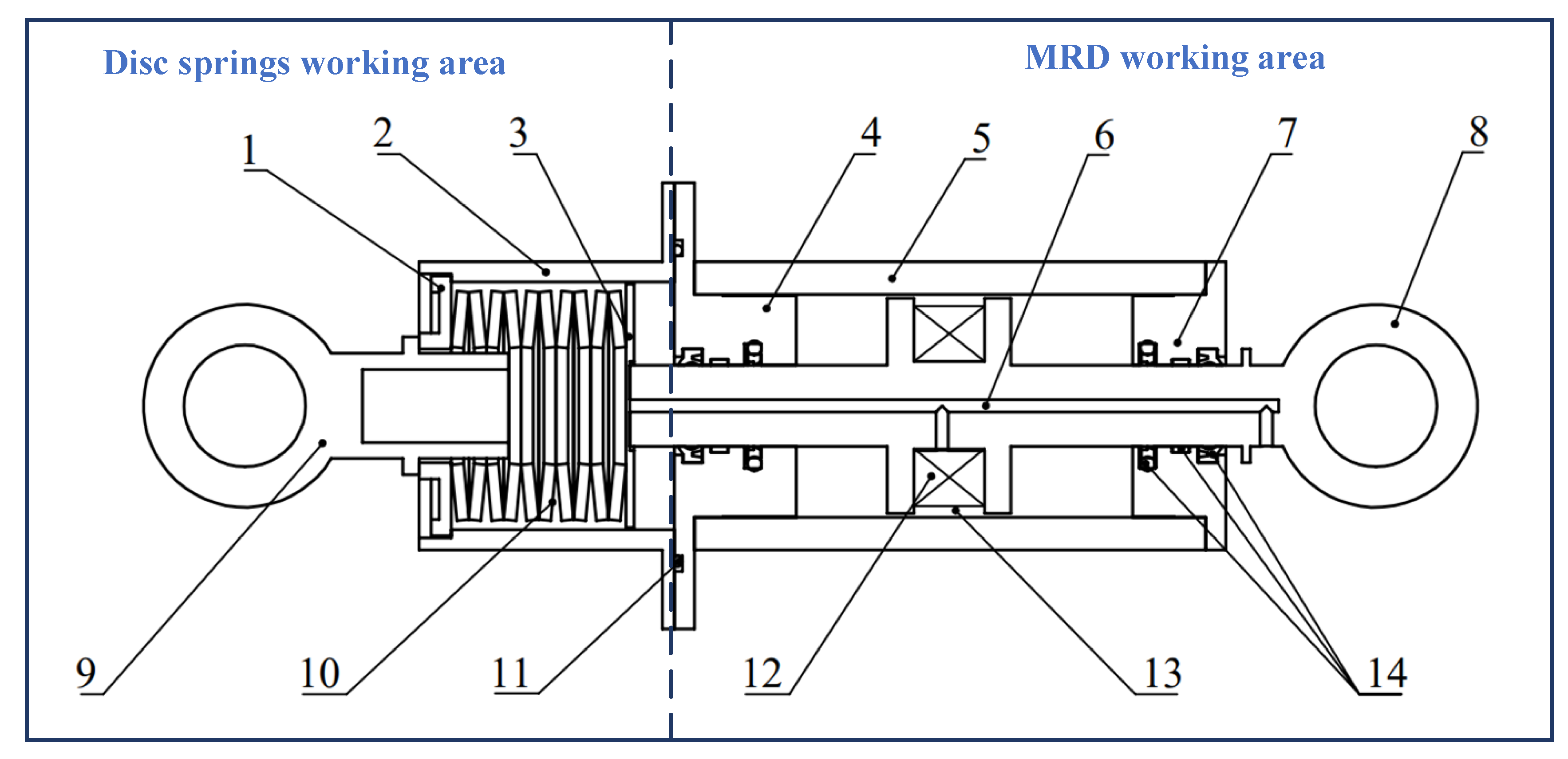
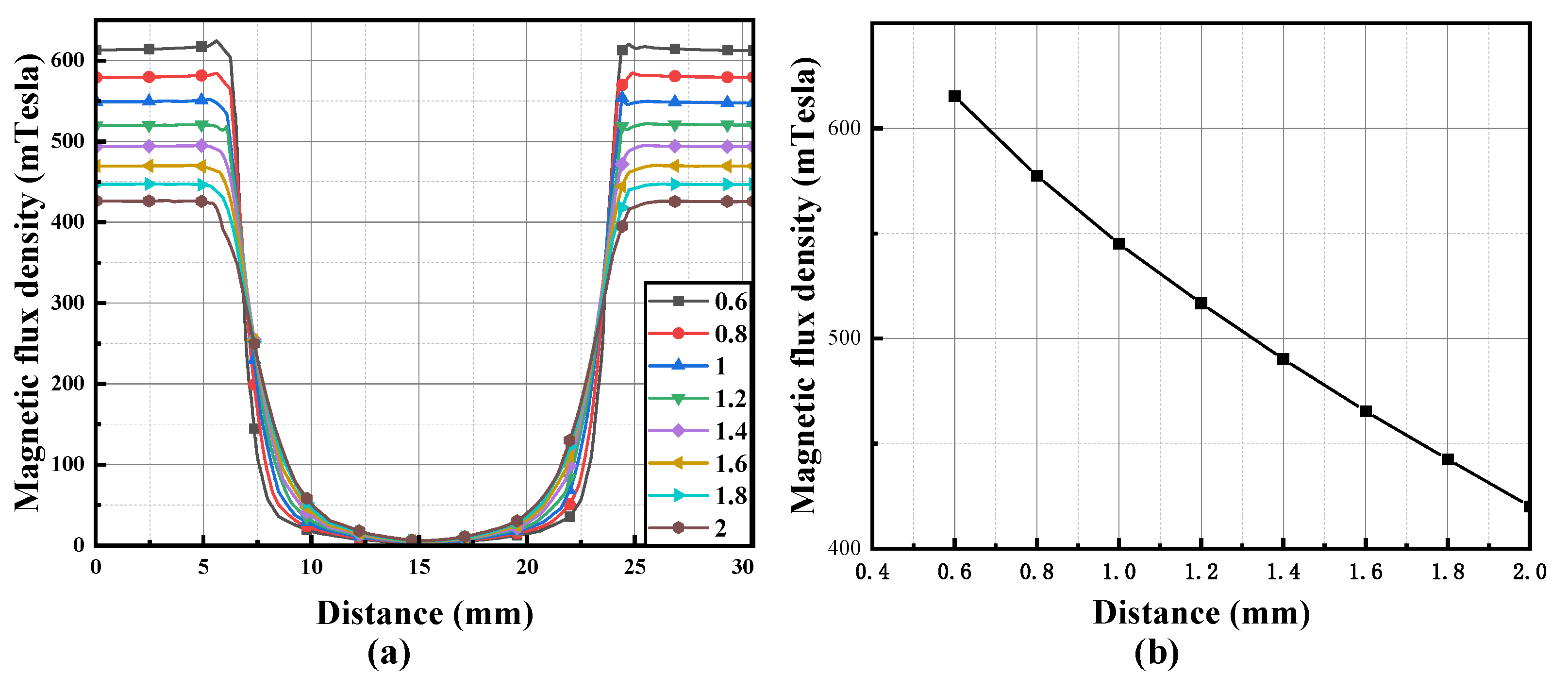
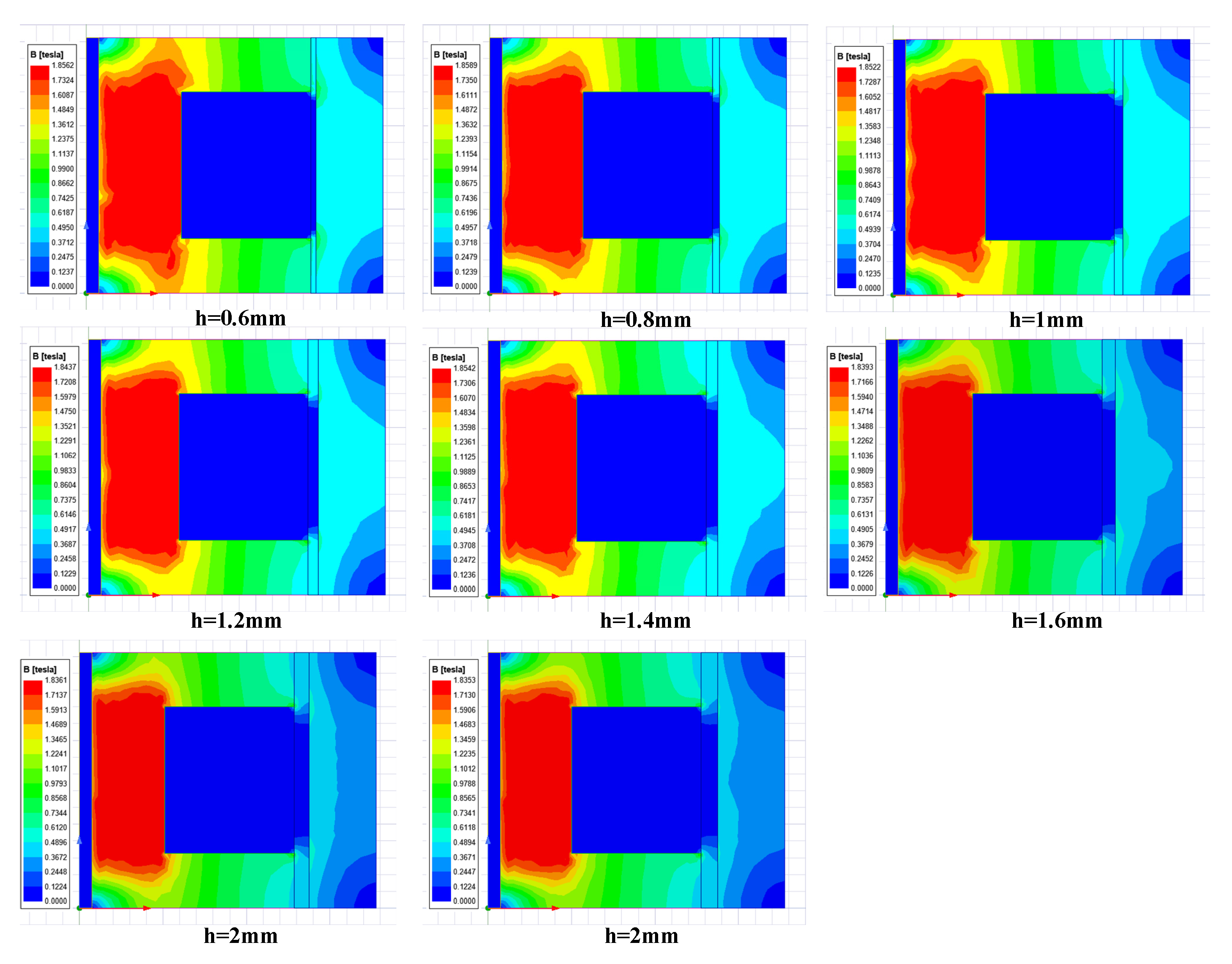
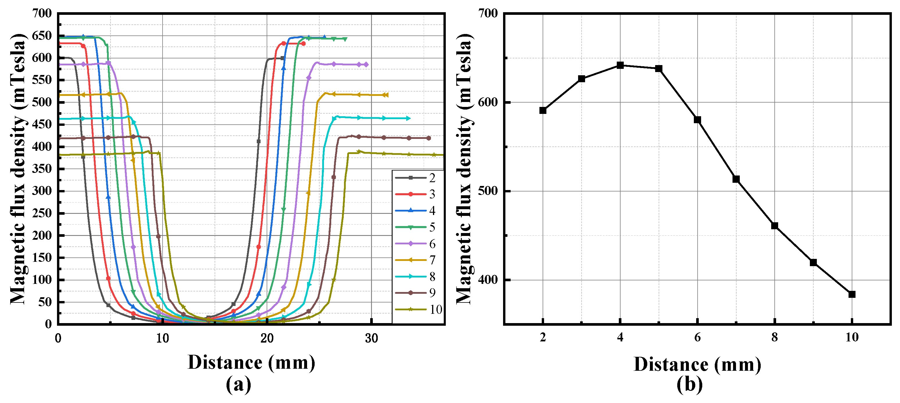
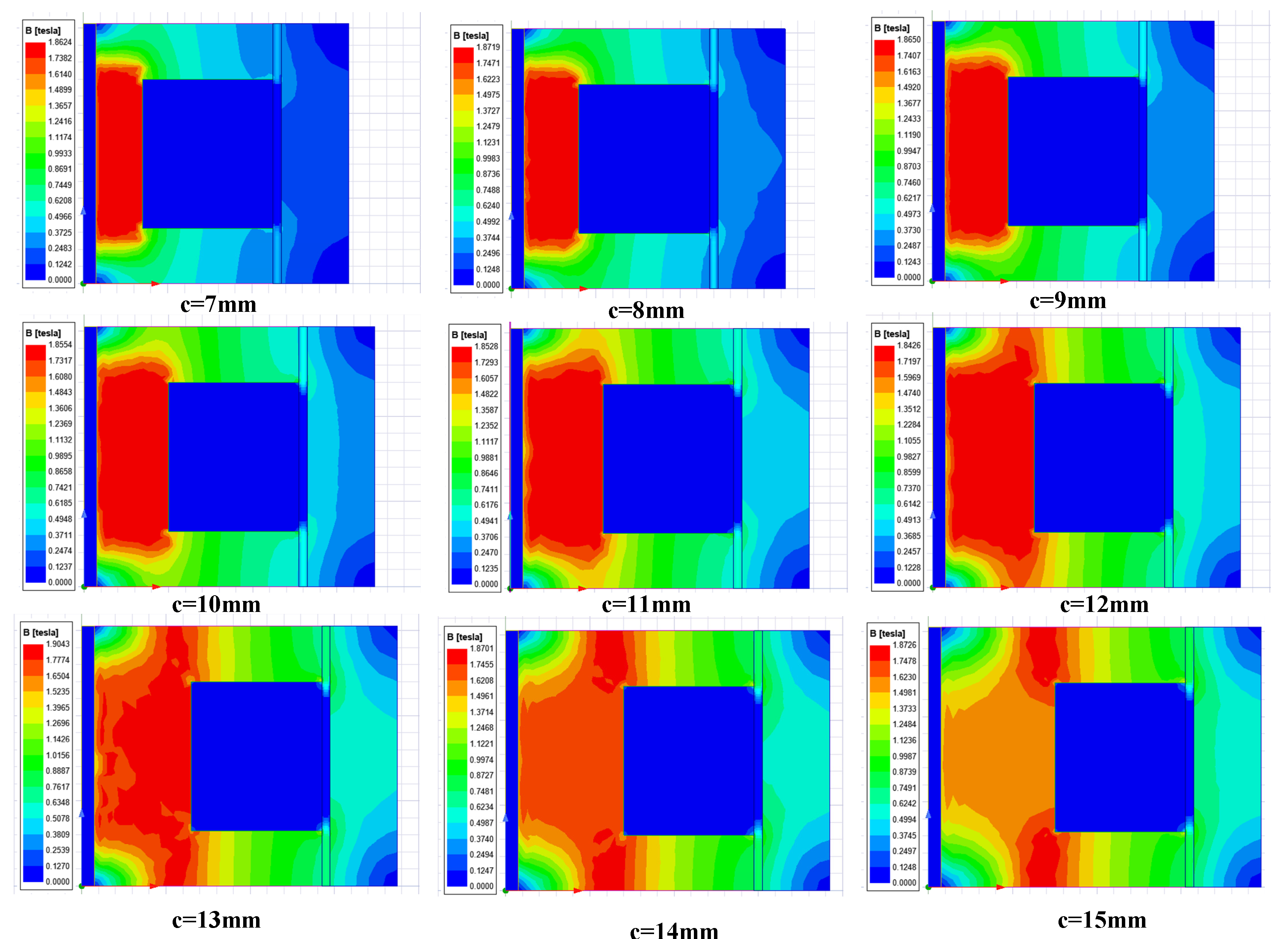
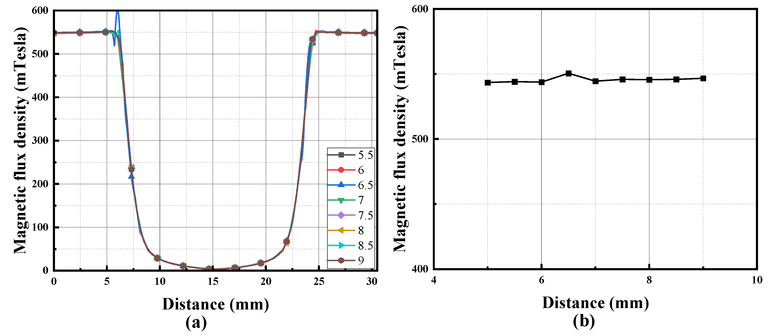
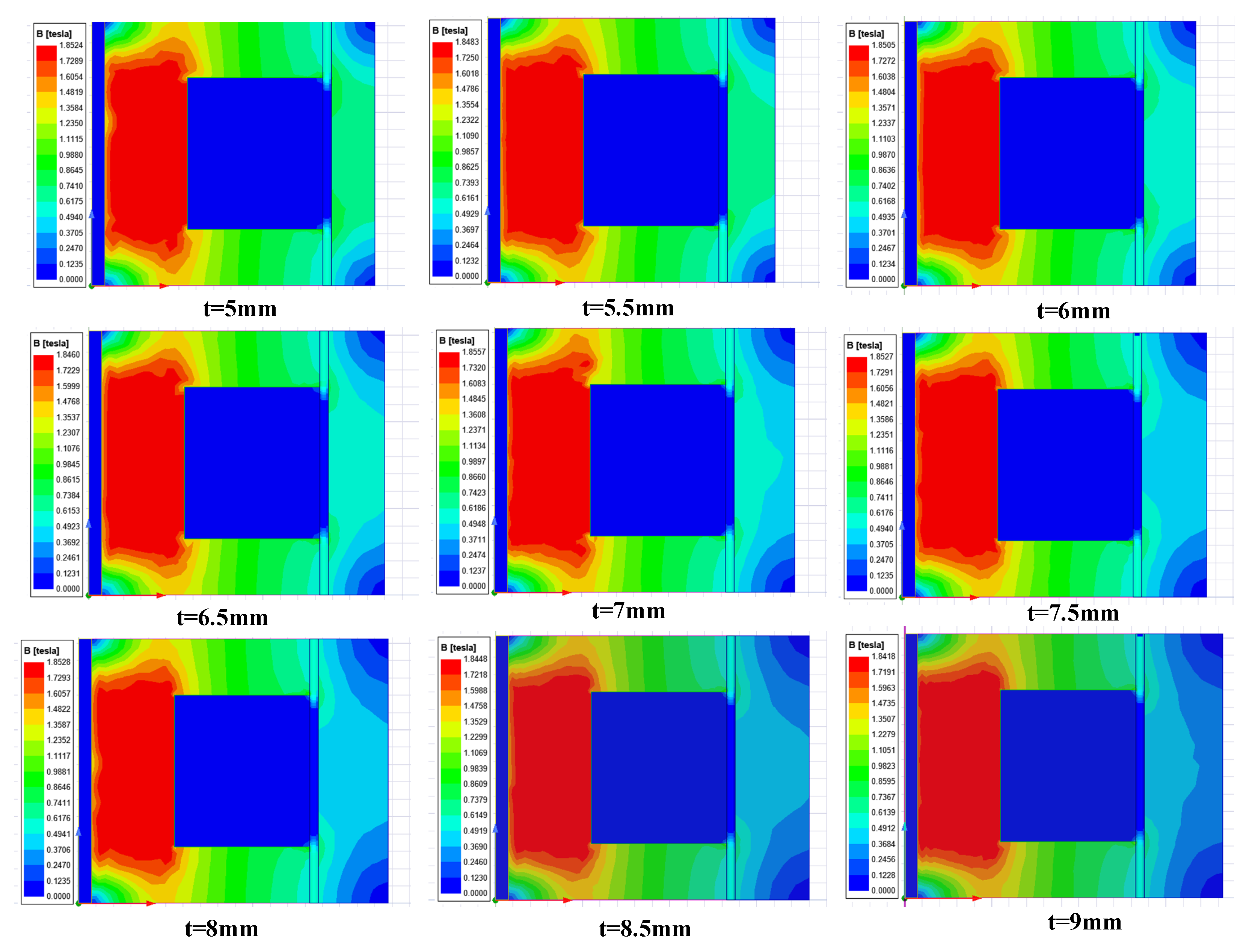
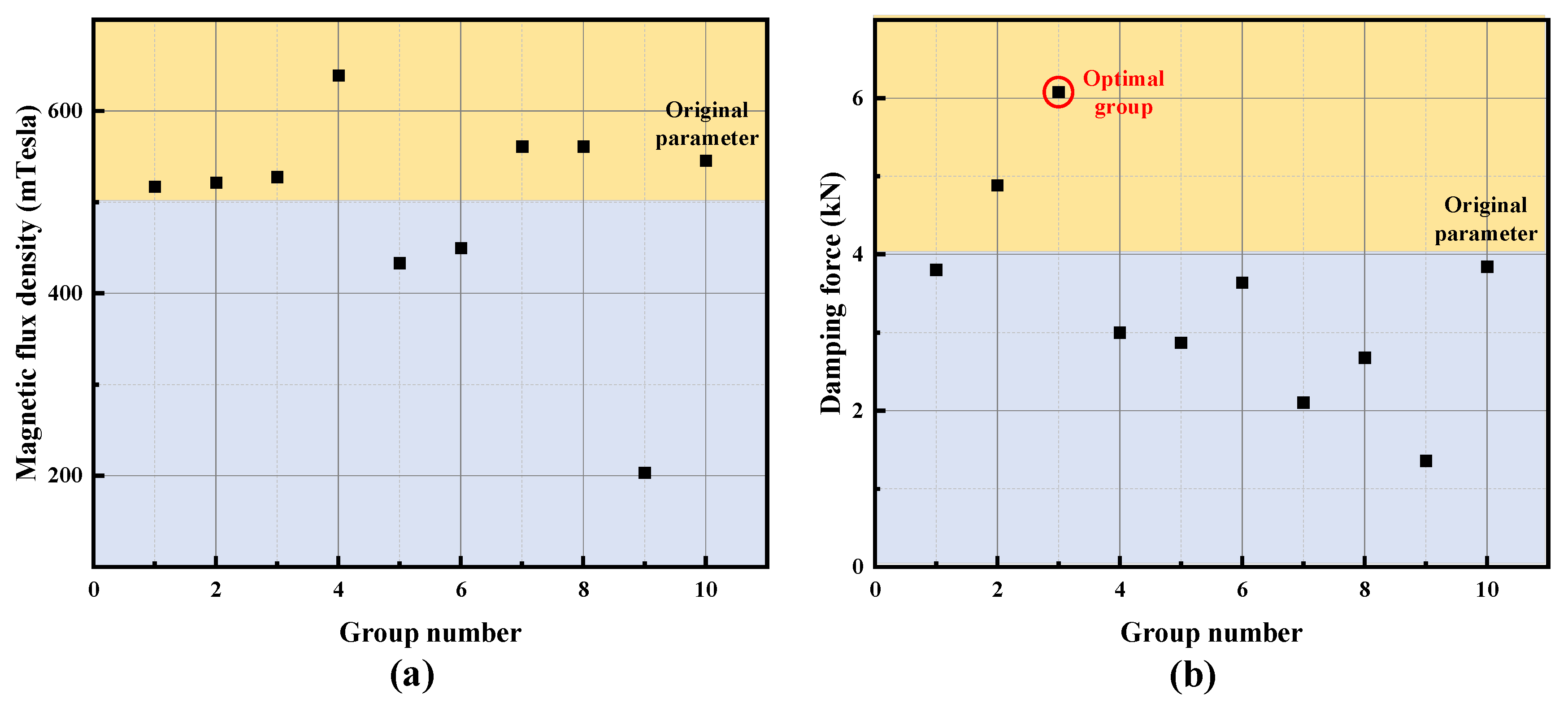
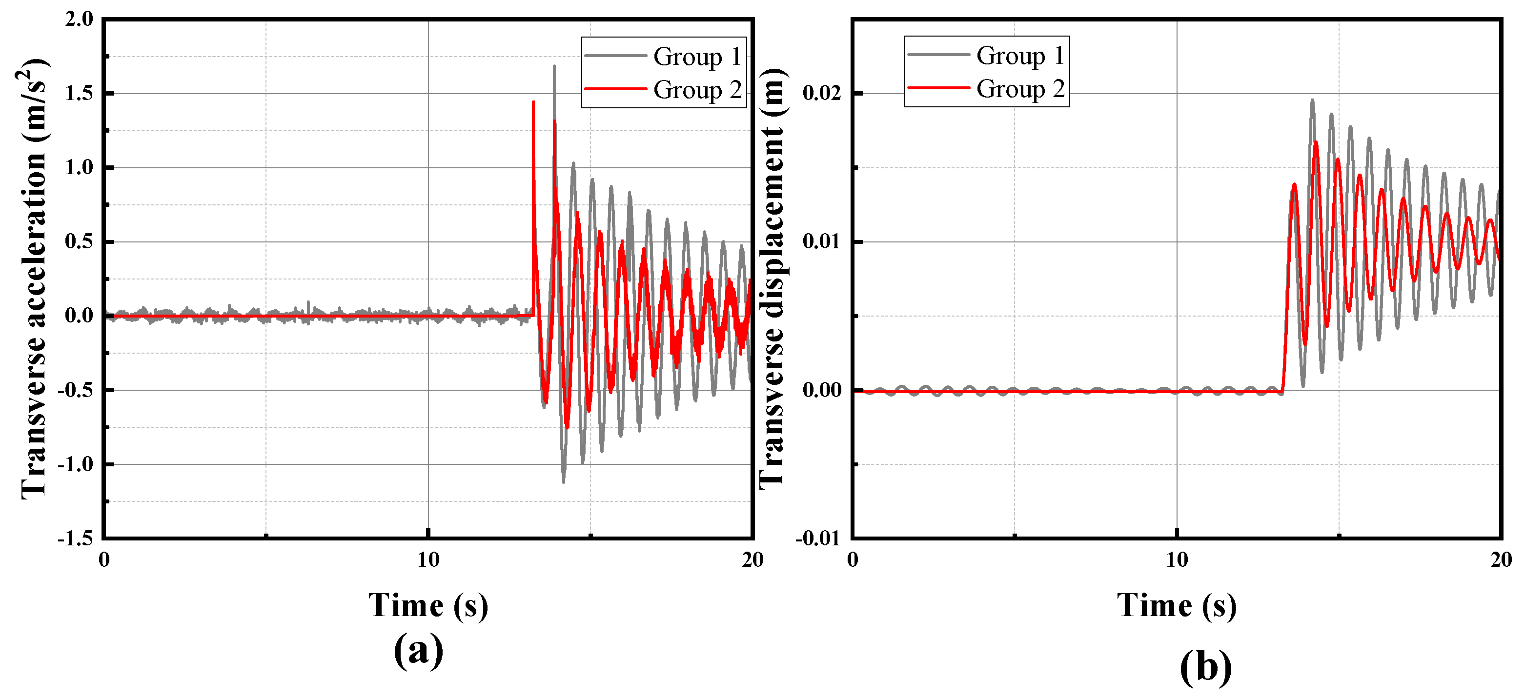
In this paper, a roller cage shoe device based on MRDs in series with a disc spring for buffering was designed. It aims to improve the operational efficiency and safety of mine hoisting system vibration-damping equipment. The structural design and magnetic circuit design of this roller cage shoe buffer were first carried out. A finite element model of the magnetic circuit was established to investigate the impact of key structural parameters on the magnetic induction intensity within the damping channel. The findings indicate that the magnetic induction intensity within the damping channel decreases as the width of the channel increases. It increases with a wider piston rod wing radius and a larger magnetic core radius. The thickness of the piston shell, however, exerts a relatively minor influence on the magnetic induction intensity. The combination of structural parameters of the magnetic circuit was optimized using the method of orthogonal tests, and the optimized MRD improved the output damping force by 58% compared with the pre-optimized one. A virtual prototype model of the MRD-based roller cage shoe buffer was created to validate the effectiveness of the optimized buffer. The simulation results demonstrate that the optimized buffer exhibits commendable damping performance and a rational design.
The conception and design of this device furnish a crucial theoretical foundation for the investigation of roller cage shoes in mine hoisting systems. Additionally, it presents a fresh design approach for optimizing lug structures. Magnetorheological dampers also have great potential in mine hoisting vibration suppression due to their advantages of fast response speeds and adjustable damping forces, which can be further explored as a semi-active control strategy based on the new type of roller cage shoe proposed in this paper, which holds substantial academic importance and practical utility in guaranteeing the secure operation of the mine hoisting system.
In the future, the on-site verification of the simulation system as well as the optimal design will be conducted to improve the reliability of the design. This is needed because this system is critical for the safety of the hoisting container. Another future work will be conducted on understanding the fault tolerance, robustness, and resilience of the system. It is noted that these concepts are relatively new, and interested readers are directed to references [22,23].

Author Contributions

Conceptualization, Y.Z. and J.Y.; methodology, R.Y.; software, R.Y., D.L. and X.D.; validation, Y.Z. and R.Y.; formal analysis, J.Y.; investigation, R.Y., D.L. and X.D.; resources, Y.Z. and J.Y.; data curation, Y.Z. and R.Y.; writing—original draft preparation, R.Y.; writing—review and editing, Y.Z. and R.Y.; visualization, Y.Z. and R.Y.; supervision, J.Y.; project administration, J.Y.; funding acquisition, J.Y. All authors have read and agreed to the published version of the manuscript.

Funding

This research was funded by the National Natural Science Foundation of China (Grant no. 51805273), the Qing Lan Project of Jiangsu Province, and the Priority Academic Program Development of Jiangsu Higher Education Institutions (PAPD).

Data Availability Statement

The data presented in this study are available on request from the corresponding author. The data are not publicly available due to privacy.

Conflicts of Interest

The authors declare no conflict of interest.

References

  1. Cao, G.; Wang, J.; Zhu, Z.; Wang, Y.; Peng, W. Lateral Response and Energetics of Cable-Guided Hoisting System with Time-Varying Length. J. Vibroeng. 2015, 17, 4575–4588. [Google Scholar]
  2. Deng, X.; Yao, J.; Liu, D.; Yan, R. Semi-Active Control of Horizontal Vibrations for Mine Hoisting Containers Using Fuzzy Skyhook Control Strategy. IEEE Access 2023, 11, 49957–49970. [Google Scholar] [CrossRef]
  3. Ma, C.; Tian, S.; Xiao, X.; Jiang, Y. Fuzzy Neural Network PID–Based Constant Deceleration Compensation Device for the Brakes of Mining Hoists. Adv. Mech. Eng. 2020, 12, 1687814020937568. [Google Scholar] [CrossRef]
  4. Jin, H.; Wang, X.; Xu, H.; Chen, Z. Reliability Evaluation of Electromechanical Braking System of Mine Hoist Based on Fault Tree Analysis and Bayesian Network. Mech. Ind. 2023, 24, 10. [Google Scholar] [CrossRef]
  5. Zhang, S.; Zhang, R.; He, Q.; Cong, D. The Analysis of the Structural Parameters on Dynamic Characteristics of the Guide Rail–Guide Shoe–Car Coupling System. Arch. Appl. Mech. 2018, 88, 2071–2080. [Google Scholar] [CrossRef]
  6. Han, Q.; Zhang, X.; Lu, Y.; Wang, L. Experimental Investigation on the In-Plane Mechanical Behavior of Elevator Guidance System. J. Build. Eng. 2023, 76, 107333. [Google Scholar] [CrossRef]
  7. He, Q.; Zhang, P.; Cao, S.; Zhang, R.; Zhang, Q. Intelligent Control of Horizontal Vibration of High-Speed Elevator Based on Gas–Liquid Active Guide Shoes. Mech. Ind. 2021, 22, 2. [Google Scholar] [CrossRef]
  8. Bao, J.; Zhang, P.; Zhu, C.; Zhu, M.; Jin, L.; Xie, H. Vibration Control of High-Speed Elevator Hoisting Systems Based on Tensioning Devices. J. Vib. Shock. 2017, 36, 221–226. [Google Scholar]
  9. Lv, H.; Zhang, S.; Sun, Q.; Chen, R.; Zhang, W. The Dynamic Models, Control Strategies and Applications for Magnetorheological Damping Systems: A Systematic Review. J. Vib. Eng. Technol. 2021, 9, 131–147. [Google Scholar] [CrossRef]
  10. Jo, B.-H.; Jang, D.-S.; Hwang, J.-H.; Choi, Y.-H. Experimental Validation for the Performance of MR Damper Aircraft Landing Gear. Aerospace 2021, 8, 272. [Google Scholar] [CrossRef]
  11. Kawase, K.; Kobayashi, N.; Yamada, M.; Nakagawa, T. Experimental Verification of Effectiveness of Magnetorheologi-Cal Fluid Damper Fixed to an Elevator in Case of Earthquake. In Proceedings of the 2018 IEEE International Magnetics Conference (INTERMAG), Singapore, 23–27 April 2018; IEEE: New York, NY, USA, 2018; p. 1. [Google Scholar]
  12. Li, X.; Wu, J.; Lu, J.; Jiao, P.; Guo, L. Design of Permanent Magnet Damper for Elevator. In Lecture Notes in Electrical Engineering, Advanced Manufacturing and Automation IX; Springer: Singapore, 2020; pp. 169–175. [Google Scholar]
  13. Zhang, H.; Zhang, R.; He, Q.; Liu, L. Variable Universe Fuzzy Control of High-Speed Elevator Horizontal Vibration Based on Firefly Algorithm and Backpropagation Fuzzy Neural Network. IEEE Access 2021, 9, 57020–57032. [Google Scholar] [CrossRef]
  14. Dos Santos, L.C.C.; Brasil, R.M.L.R.F.; Balthazar, J.M.; Piccirillo, V.; Tusset, A.M.; Santo, D.R. Active Vibration Control of an Elevator System Using Magnetorheological Damper Actuator. Int. J. Nonlinear Dyn. Control 2017, 1, 114. [Google Scholar] [CrossRef]
  15. Wu, M.; Chen, F.; Li, A.; Chen, Z.; Sun, N. A Novel Vibration Isolator for Vibrating Screen Based on Magnetorheological Damper. J. Mech. Sci. Technol. 2021, 35, 4343–4352. [Google Scholar] [CrossRef]
  16. Yao, J.; Ma, Y.; Ma, C.; Xiao, X.; Xu, T. Effect of Misalignment Failures of Steel Guides on Impact Responses in Friction Mine Hoisting Systems. Eng. Fail. Anal. 2020, 118, 104841. [Google Scholar] [CrossRef]
  17. Yang, G.; Spencer, B.F.; Carlson, J.D.; Sain, M.K. Large-Scale MR Fluid Dampers: Modeling and Dynamic Performance Considerations. Eng. Struct. 2002, 24, 309–323. [Google Scholar] [CrossRef]
  18. Almen, J.O.; Laszlo, A. The Uniform-Section Disk Spring. Trans. Am. Soc. Mech. Eng. 1936, 58, 305–314. [Google Scholar] [CrossRef]
  19. Park, E.J.; Stoikov, D.; da Luz, L.F.; Suleman, A. A Performance Evaluation of an Automotive Magnetorheological Brake Design with a Sliding Mode Controller. Mechatronics 2006, 16, 405–416. [Google Scholar] [CrossRef]
  20. Pan, L.; Chen, J. Experimental Design and Data Process; Southeast University Press: Nanjing, China, 2008; p. 353. ISBN 978-7-5641-1128-1. [Google Scholar]
  21. Wang, Y.; Cao, G.; Wang, N.; Peng, W. Dynamic Responses of Cable-Driven Parallel Sinking Platform. Math. Comput. Model. Dyn. Syst. 2017, 23, 104–115. [Google Scholar] [CrossRef]
  22. Wang, F.; Qian, Z.; Yan, Z.; Yuan, C.; Zhang, W. A Novel Resilient Robot: Kinematic Analysis and Experimentation. IEEE Access 2019, 8, 2885–2892. [Google Scholar] [CrossRef]
  23. Zhang, T.; Zhang, W.; Gupta, M.M. Resilient Robots: Concept, Review, and Future Directions. Robotics 2017, 6, 22. [Google Scholar] [CrossRef]
Figure 1. Mine hoisting systems. (a) main view; (b) top view; (c) actual picture.
Applsci 13 12506 g001
Figure 2. Conventional roller cage shoe.
Applsci 13 12506 g002
Figure 3. Structure of an MRD-based buffer: 1. disc spring baffle; 2. sleeve; 3. damping baffle; 4. bottom cover; 5. cylinder barrel; 6. piston channel; 7. topside cover; 8. piston rod; 9. guide bar; 10. disc spring; 11. seal; 12. coil; 13. damping gap; 14. sealing assembly.
Applsci 13 12506 g003
Figure 4. Rheological mechanical model of the MRD. (a) Simplified model; (b) shear valve mode.
Applsci 13 12506 g004
Figure 5. The characteristic curve of MRF-J25T: (a) τ-B curve; (b) H-B curve.
Applsci 13 12506 g005
Figure 6. Magnetic circuit simplified design schematic.
Applsci 13 12506 g006
Figure 7. B-H curve of 20# steel.
Applsci 13 12506 g007
Figure 8. Simulation analysis model.
Applsci 13 12506 g008
Figure 9. Simulation results of damping gap with different lengths. (a) Plot of magnetic induction intensity versus distance; (b) plot of average magnetic induction intensity versus distance.
Applsci 13 12506 g009
Figure 10. Plot of magnetic induction intensity clouds corresponding to different lengths of damped gaps.
Applsci 13 12506 g010
Figure 11. Simulation results of piston rod wing radius with different lengths. (a) Plot of magnetic induction intensity versus distance; (b) plot of average magnetic induction intensity versus distance.
Applsci 13 12506 g011
Figure 12. Plot of magnetic induction intensity clouds corresponding to different lengths of piston rod wing radius.
Applsci 13 12506 g012
Figure 13. Simulation results of the core radius with different lengths. (a) Plot of magnetic induction intensity versus distance; (b) plot of average magnetic induction intensity versus distance.
Applsci 13 12506 g013
Figure 14. Plot of magnetic induction intensity clouds corresponding to different lengths of core radius.
Applsci 13 12506 g014
Figure 15. Simulation results of cylinder thickness with different lengths. (a) Plot of magnetic induction intensity versus distance; (b) plot of average magnetic induction intensity versus distance.
Applsci 13 12506 g015
Figure 16. Plot of magnetic induction intensity clouds corresponding to different lengths of cylinder thickness.
Applsci 13 12506 g016
Figure 17. Simulation results of orthogonal tests. (a) Comparison of average magnetic induction intensity with different parameter combinations; (b) comparison of maximum damping force with different parameter combinations.
Applsci 13 12506 g017
Figure 18. Virtual prototype model of mine hoisting system: (a) mine hoisting system; (b) roller cage shoe; (c) interface misalignment.
Applsci 13 12506 g018
Figure 19. Sample curve of the MRD.
Applsci 13 12506 g019
Figure 20. Transverse vibration responses of conveyance excited by interface misalignment: (a) transverse acceleration; (b) transverse displacement.
Applsci 13 12506 g020
Table 1. Parameters of MRF-J25T.
Material ParametersValue/Range
Volume ratio of ferromagnetic particles25%
Baseline liquidHydrocarbon oil
Density2.65 g/m3
Zero-field viscosity0.8 Pa·s
Shear stress>50 kPa
Applicable temperature−25~130 °C
Table 2. Parameters of disc springs.
ParameterSymbolDimensions
External diameterD56 mm
Inside diameterd28.5 mm
Thicknessest3 mm
Free heightH04.3 mm
Extreme travelh01.3 mm
Densityρ7850 kg/m3
Modulus of elasticityE206 GPa
Poisson’s ratioμ0.3
Table 3. Main parameters of the MRD.
ParameterDataParameterData
Cylinder bore71 mmDepth of trench15.5 mm
Damped channel width1 mmWidth of trench17.5 mm
Piston outer diameter53 mmFlank width13 mm
Cylinder thickness8 mmCore radius22 mm
Piston rod radius20 mmTurns of the coil300
Table 4. Model parts and materials.
SymbolPartsMaterials
A1Piston rod cavityVacuums
A2Piston rod20 steel
A3CoilCopper
A4Damped channelMRF-J25T
A5Cylinder20 steel
Table 5. Levels of each factor.
FactorLevel 1Level 2Level 3
h/mm0.811.2
l/mm567
c/mm91011
t/mm77.58
Table 6. Table of test factor parameters.
Group NumberHorizontal CombinationStructure/mm
hlct
1h1 L1 c1 t10.8597
2h1 L2 c2 t20.86107.5
3h1 L3 c3 t30.87118
4h2 L1 c3 t215117.5
5h2 L2 c1 t31698
6h2 L3 c2 t117107
7h3 L1 c2 t31.25108
8h3 L2 c3 t11.26117
9h3 L3 c1 t21.2797.5
Table 7. Material properties.
ParameterDensity Modulus of Elasticity Poisson’s Ratio
Polyurethane1 × 10−6 kg/mm325 N/mm20.49
iron7.8 × 106 kg/mm32.07 × 105 N/mm20.29
Table 8. Constraint relationship for roller cage shoe buffers.
Part 1Part 2Constraint Relation
Bolt 1BaseFixed pair
Bolt 1Rocker armRevolute pair
Bolt 2Rocker armFixed pair
Bolt 2Rollerpiston rod
Bolt 3Rocker armFixed pair
Bolt 3Piston rodFixed pair
Bolt 4Guide barFixed pair
Bolt 4BaseFixed pair
Table 9. Transverse vibration simulation parameters of a hoisting conveyance.
ParameterNumerical ValueUnit
Conveyance mass34,000kg
Lift height300m
The moment of inertia of the conveyance concerning the transverse direction208,000kg·m2
The moment of inertia of the conveyance concerning the longitudinal direction33,100kg·m2
The moment of inertia of the conveyance concerning the lateral direction234,000kg·m2
The lateral direction spring stiffness2,250,000N/m
The lateral direction spring damping16,400N·s/m
Table 10. Comparison of simulation results.
Group 1Group 2
RMS0.30380.1814
Maximum value1.68483121.4444
Disclaimer/Publisher’s Note: The statements, opinions and data contained in all publications are solely those of the individual author(s) and contributor(s) and not of MDPI and/or the editor(s). MDPI and/or the editor(s) disclaim responsibility for any injury to people or property resulting from any ideas, methods, instructions or products referred to in the content.

