Abstract
The inertial Navigation Systems/global navigation satellite system (SINS/GNSS) has become a research hotspot in the field of train positioning. However, during a uniform straight-line motion period, the heading misalignment angle of the SINS/GNSS is unobservable, resulting in the divergence of the heading misalignment angle and ultimately causing a divergence in the train’s speed and position estimation. To address this issue, this paper proposes an estimation and compensation method for the heading misalignment angle for train SINS/GNSS integrated navigation system based on an observability analysis. When the train enters a straight-line segment, the alignment of the train’s sideslip angle and the satellite velocity heading angle allows the achievement of velocity heading observation values that resolve the issue. In a curved segment, the heading angle becomes observable, allowing for an accurate estimation of the SINS’s heading misalignment angle using GNSS observations. The results showed that, whether the train is on a straight or curved track, the position estimation accuracy meets the simulation design criteria of 0.1 m, and the heading accuracy is better than 0.25°. In comparison to the results of pure GNSS position and velocity-assisted navigation, where heading divergence occurs during constant velocity straight-line segments, the method proposed in this paper not only converges but also achieves an accuracy comparable to the GNSS velocity-based heading alignment. The simulation results demonstrate that the proposed strategy significantly improves the accuracy of the heading misalignment angle estimation, thereby enhancing the accuracy of speed and position estimation under a GNSS-denied environment.
1. Introduction
Currently, there are two main methods for determining train positioning: one is the combination of signal lights and odometers [1,2,3], and the other is based on satellite signals and multi-sensors fusion [4]. The combination of signal lights and odometers is the most commonly used train positioning method at present [5]. This method utilizes the position information provided by signal lights to correct the cumulative errors of the odometer. However, it has the disadvantage of high cost of construction and maintenance, especially in Western China [6]. The global navigation satellite system (GNSS) signal positioning method is required to be installed on the top of a train’s receiving antennas to receive signals from multiple satellites and calculate the accurate position of the train [7,8,9]. Its advantages include global coverage, high positioning accuracy, and real-time performance [10,11,12]. However, GNSS signals may be attenuated in environments with dense obstructions such as urban areas, tunnels, or forests, leading to inaccurate train positioning [13,14,15].
Inertial navigation systems (INS) measure a train’s speed and directional changes using inertial sensors and calculate its current position based on its initial position using dead reckoning [16,17,18]. Its advantages include independence from external signals, good real-time performance, reliability even in signal-obstructed environments, and the ability to obtain comprehensive navigation information, including speed, position, and attitude [19,20,21]. However, due to the working principle of dead reckoning, INS is susceptible to cumulative errors, which gradually increase over time and require correction through other means [22]. The SINS/GNSS integrated navigation system, consisting of INS and GNSS, leverages information fusion to obtain real-time navigation data for the train, including attitude, speed, and position. By overcoming the issue of INS error divergence over time, this system has the potential to become the new mainstream equipment for train speed and location measurement [23,24,25].
However, based on an observability analysis, it is inferred that, during a uniform straight-line motion, the heading misalignment angle of the train SINS/GNSS integrated navigation system is unobservable, leading to a significant problem of large heading misalignment angles that ultimately causes a low precision in train speed and position estimation [26,27]. The errors in inertial navigation solution are also strongly correlated with the dynamic characteristics of the moving platform [28]. For a train, which is constrained to a one-dimensional motion on the track, its motion trajectory can be decomposed into straight lines and curves, with its motion on the track mainly divided into acceleration and deceleration phases and uniform motion phases [29]. Therefore, the errors in inertial navigation solution can be analyzed through the decomposition and combination of the train’s motion trajectory and dynamic modes. Using an observability analysis, it is found that the heading misalignment angle during the most dominant motion mode of the train, i.e., uniform straight-line motion, is unobservable when aided by position and velocity information [30,31]. When entering a satellite signal blockage scenario, the accumulated heading misalignment angle will have a cubic impact on the train’s position accuracy and a quadratic impact on the train’s speed accuracy with respect to the navigation time [32]. The estimation of attitude is closely related to the maneuvering mode of the moving platform, especially the estimation of the heading angle. By analyzing the train’s motion modes, it is observed that pitch and roll angles are strongly observable, and thus, the roll and heading angles can be accurately estimated throughout the entire train route [33]. However, the heading angle is unobservable during the train’s uniform straight-line motion, which severely affects the accuracy of position and speed estimation when satellite signals are lost.
To solve this problem, this paper proposes an estimation and compensation method for the train SINS/GNSS integrated navigation system based on an observability analysis. As the train’s motion is constrained to the track, the velocity heading angle will be highly accurate under high-speed conditions. This paper primarily utilizes this valuable information to estimate the zenith gyro zero bias, thereby achieving the precise estimation of the heading misalignment angle. Depending on the different track segments of the train’s movement, the observability of the heading angle continuously changes. Specifically, the heading angle is unobservable during straight-line segments, but it becomes fully observable with the availability of satellite velocity heading angle. Additionally, when the train enters a curved segment, the heading angle gains observability, and the observability strengthens with an increased curvature. Therefore, in a train-positioning system primarily based on inertial navigation, it is necessary to estimate the inertial navigation attitude misalignment angle before satellite navigation fails. One feasible approach is to estimate the attitude misalignment angle before entering a signal-unavailable track segment such as a tunnel. The following measures can be adopted: Firstly, introducing a new responder technology, namely, the attitude position responder, where the solution of a virtual attitude responder has been proposed by France’s ixblue company. Secondly, using GNSS velocity heading information for heading correction. The analysis of this strategy will be elaborated below.
According to the results of [34], the train tracking, stopping, and starting in the zone of the train’s longitudinal accuracy requirements vary between 50 m, 13 m, 5 m, and 0.5 m. This paper adopts the SINS/GNSS integrated navigation framework, which can meet the requirements of the train-positioning accuracy under the circumstance of the unavailability of GNSS. When GNSS is unavailable, it is derived from the observability analysis, after the train travels a distance in a straight line at a constant speed, with the assistance of position measurement, the heading angle is still not observable, but it can be analyzed by simulation depending on which grade of inertial guidance device accuracy is used to meet the final train-positioning accuracy requirements, which is an important basis for the allocation of error margins in the design of the combined navigation system and the selection of the device accuracy.
The paper is divided into four sections. Section 1 introduces background information, the problem, and a literature review related to this issue. Section 2 elaborates on the detailed construction process of the system equations, measurement equations, and observability analysis in the proposed method. Section 3 involves the simulation and analysis of the theoretical results. Section 4 summarizes the main findings of the entire paper.
2. Train SINS/GNSS Integrated Navigation System Model
In this study, the “east-north-up” (ENU) geographic coordinate system is selected as the navigation reference coordinate system, denoted as n The computed navigation reference coordinate system based on navigation solutions is denoted as n′. Additionally, the “right-front-up” (RFU) coordinate system is chosen as the carrier coordinate system with the inertial measurement unit (IMU) as the origin, denoted as the coordinate system. The e coordinate system is defined as a coordinate system in the equatorial plane, where x intersects the Greenwich meridian and z coincides with the polar axis North. To leverage the constraint that the train moves on the track and simplify the problem while capturing key elements, we assume that the train’s motion is constrained to a two-dimensional plane. The motion of the train, either in straight lines or curves, is illustrated in Figure 1. During turning, there is a sideslip angle during turning, which is the angle between the direction of train velocity and the extension of the train carriage’s central axis, as shown in Figure 2.
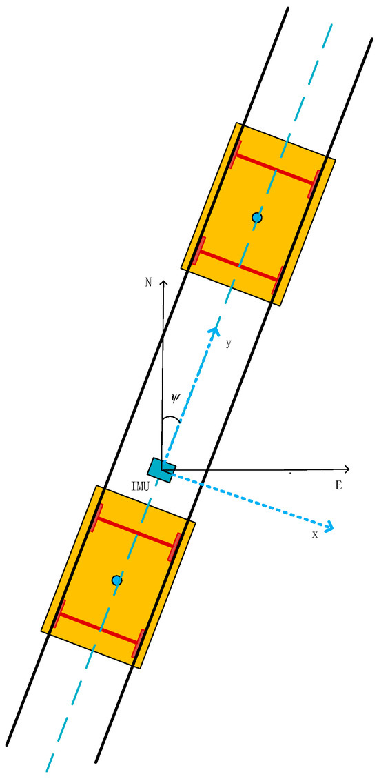
Figure 1.
Train’s straight-line motion and coordinate system definition. (black line: rail; red line: bogie axle; blue dot: blue dot: center point of train carriage).
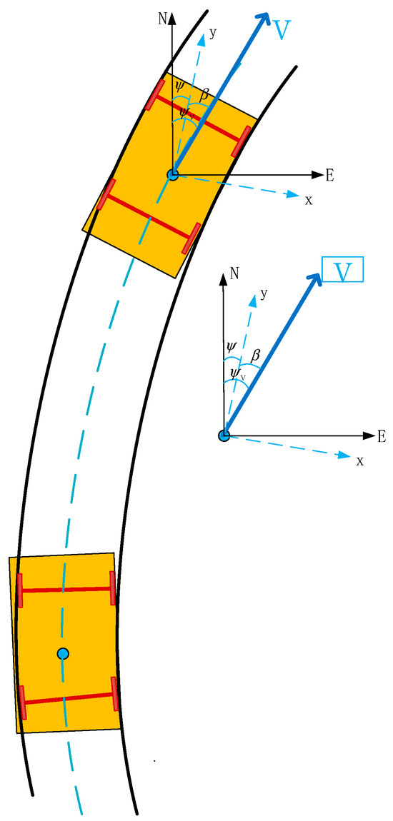
Figure 2.
Train’s curved motion and sideslip angle schematic. (black line: rail; red line: bogie axle; blue dot: blue dot: center point of train carriage).
2.1. SINS State Equation
We use the expanded Kalman filter (EKF) as our data fusion architecture and loosely coupled loop integration architecture for the data of GNSS and INS. The state quantity is chosen as the error state, and the whole process is shown in Figure 3.
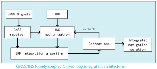
Figure 3.
Schematic diagram of the integration scheme of the GNSS/INS system.
In order to emphasize the role of observability analysis in train positioning and to simplify the theoretical derivation process, train motion is simplified to a motion in a two-dimensional plane. This makes it easier to highlight the non-observability of heading when the train is moving in a uniform straight line. Thus, only two horizontal accelerometers and one celestial gyroscope are used in the article instead of the usual inertial measurement component including three gyroscopes and three accelerometers. The error equation for inertial navigation is as shown in Equation (1):
where, , , represents position, speed, and attitude. represents the projection of the angular velocity of the n-system relative to the e-system under the n-system, represents the projection of the angular velocity of the n-system relative to the inertial coordinate system under the n-system, represents the projection of the angular velocity of the e-system relative to the inertial coordinate system under the n-system, The superscript n denotes the projection into the n-coordinate system and the prefix δ denotes the error of the corresponding variable, represents the rotation matrix of the b system relative to the n system. The error of the specific force vector resolved in the n-frame is referred to as , while the error of gyro output is denoted as .
To use the error-state Kalman filter as the combination framework for integrated navigation computation, the continuous-time system equation used is as follows:
where X is the system state, F is the system matrix, G is the noise covariance matrix, and is the system noise.
The system error state is as follows:
where represents the misalignment angle in the heading axis between the computed navigation frame and the relative navigation frame; are the eastward and northward position errors; are the eastward and northward velocity errors; are the eastward and northward accelerometer biases; and represents vertical gyroscope drift. Under the conditions of plane navigation for trains, due to the gyroscope drift, there is a misalignment angle between the integrated true heading angle and the computed heading angle .
where is noise of gyroscope.
Position error differential equation is as follows:
where represents position, and represents velocity.
For the velocity error differential equation, after expanding the three-dimensional attitude error equation, there are more than ten error terms, making it difficult to identify error propagation patterns. However, in the context of train applications, assuming a two-dimensional plane navigation, the velocity error differential equation becomes relatively simple, with a clearer physical meaning. Based on the specific force differential Equation (1) and neglecting the effect of Earth’s curvature, i.e., = 0, and considering that the Earth’s rotational speed is 10−5 rad/s in magnitude, while train speeds are typically lower than 100 m/s, in the derivation of the error equation for short-term plane navigation, we can simplify the specific force differential Equations (6) and (7).
In the two-dimensional plane assumption, according to the definition of the heading angle in Figure 1, we obtain the following equation:
where represents the heading angle.
To simplify the specific force equation, we use the following equation:
Similar to the anti-matrix of a three-dimensional vector, here, we define a two-dimensional antisymmetric matrix and is as follows:
Then, we obtain the following:
Substituting Equation (11) into Equation (9) and simplifying, we obtain the following:
According to the theory of linear systems, when a coefficient of the system has a linearly unrelated change to other coefficients under certain conditions, and both the measurement and state coefficients are known, then that state is considered to have an analytical solution and is observable. As the corresponding coefficient of that state changes more significantly, its susceptibility to noise decreases, leading to a higher observability. However, when the train is in a state of constant velocity and linear motion, the train’s acceleration output is equal to zero; thus, the coefficient in front of the heading misalignment angle error is zero. Therefore, the heading is unobservable when the train is in a state of constant velocity and linear motion.
From the velocity calculated in Equation (1), we obtain the following:
where c represents cos, and s represents sin.
Because , the pitch and roll misalignment angles have strong observability from above observability analysis, while the heading misalignment angle is unobservable when the train is in a state of constant linear motion due to the zero acceleration output. During constant linear motion, the coefficients in front of and will never be zero, so the bias is always observable. To avoid being influenced by irrelevant coefficients in the inertial navigation error equation and to better focus on the problem, a simplified model is chosen for problem analysis. The main estimation parameters are the train’s position, velocity, and heading angle.
Specifically, both the velocity error caused by heading error and the position error caused by velocity integration do not contain heading error components. They cannot be estimated or corrected for by velocity or position aiding measurements. Therefore, in the navigation state where the train, especially high-speed trains, mostly operates in a state of constant linear motion, the heading is unobservable in the GNSS/SINS integration framework, and it will continuously diverge. Additionally, since the integration of the vertical gyroscope drift results in heading error , the vertical gyroscope drift will also diverge.
In the case of GNSS signal availability, heading error does not affect the train’s requirements for speed and position estimation. However, once GNSS fails and the system switches to an inertial-based navigation mode, heading error directly leads to inaccurate velocity and position estimates. When the train is in a state of acceleration or deceleration, and are not zero. When the train passes through curved sections, there are tangential acceleration and centripetal acceleration, and the projection in the b-frame also makes, not zero. Therefore, the heading error is observable when the train passes through curved sections. The summary of heading observability analysis for different motion modes and track curvatures is shown in Table 1.

Table 1.
List of heading observability in different motion modes and track curvatures.
Gyroscopes and accelerometers are modeled as first-order Markov processes [35], and the models are listed in Appendix A.
The F and G matrices of system equations are listed in Appendix B.
2.2. Measure Equation
The measured quantities include position, velocity, and heading measurements. In this context, “position” can refer to either GNSS position measurements or known reference points; “velocity” measurements can be the GNSS velocity or the odometer velocity, among others; and “heading” measurements can be from GNSS dual antennas, track centerline electronic map heading angles, or dual-wheel speedometer heading measurements.
For position measurements, we use the following equation:
where p represents position.
For velocity measurements, we use the following equation:
where v represents position.
For heading measurements, we use the following equation:
where represents heading angle.
The system equations decouple the heading obtained from the other states, and when heading measurements are available, both the heading misalignment angle and gyroscope bias will converge as follows:
Equations (17) and (18) are transformed into matrix forms and provided as Equations (19) and (20), respectively.
Then, Equations (14)–(21) are transformed into the standard Riccati differential equation as shown in Equation (22).
In Equation (22), represents the covariance matrix, is the system matrix that can be expressed as , is the measurement matrix that can be expressed as , is the measurement noise, and is the system noise based on matrix calculations. The analytical solution for the matrix can be obtained as follows:
The Δ’s magnitude is of the order of t4 in terms of time ; thus, the will eventually converge to zero. Therefore, according to the definition of random observability, when accurate velocity and heading observations are available, the heading will converge.
3. Simulation and Analysis
The parameters of SINS inertial devices and GNSS error parameters in the simulation experiment are set as shown in Table 2. We use MATLAB to perform the simulation studies, the real train trajectory and speed are simulated first, and then, the GNSS observations are simulated by adding Gaussian white noise to the train trajectory and speed information. The generation of gyro and accelerometer increments in the IMU data is implemented based on the inertial navigation inversion algorithm, and the device noise is generated based on the first-order Markov process.
Table 2.
SINS inertial device parameters and GNSS error parameter settings.
- (1)
- Straight line
Position and heading truth values are generated using the train trajectory and speed simulation. Under the given conditions specified in Table 2, the combination navigation process of GNSS/SINS during the train’s constant velocity straight-line motion is simulated. The results for the train’s position and velocity are shown in Figure 4. Figure 5 demonstrates that, with the assistance of GNSS position and velocity, the navigation results are bounded, with the position converging to approximately 0.1 m.
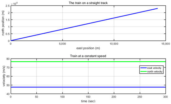
Figure 4.
Diagram of a train’s constant velocity straight-line motion trajectory and velocity.
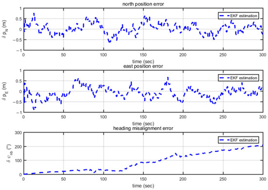
Figure 5.
Velocity and position-assisted navigation of a train’s constant velocity straight-line motion.
During 300 s of navigation time, the heading misalignment angle linearly diverges, confirming the earlier theoretical analysis that the heading is unobservable under a constant velocity straight-line motion. Figure 6 displays the estimated values of gyro and accelerometer biases. The accelerometer bias converges to the simulated setting of 0.1 g. However, under the condition of constant velocity straight-line motion, the gyro bias, which was initially set at 0.05°/s, diverges to nearly 0.05°/s within 300 s.
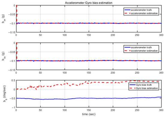
Figure 6.
Gyro and accelerometer bias during a train’s constant velocity straight-line motion.
In summary, the accelerometer bias exhibits a strong observability during a constant velocity straight-line train motion, while the heading gyro bias is unobservable. The simulation results are consistent with those of the theoretical analysis.
- (2)
- Curved line
To further validate the observability of the train’s heading angle on curved tracks, simulations were conducted on a curved trajectory, with their corresponding trajectory and velocity shown in Figure 7. The minimum curvature radius is approximately 5500 m, as depicted in Figure 8, which complies with the high-speed rail’s minimum curvature radius requirements.
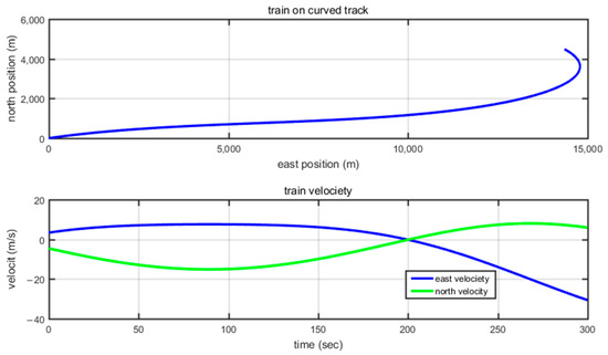
Figure 7.
Train’s position and velocity on the curve.
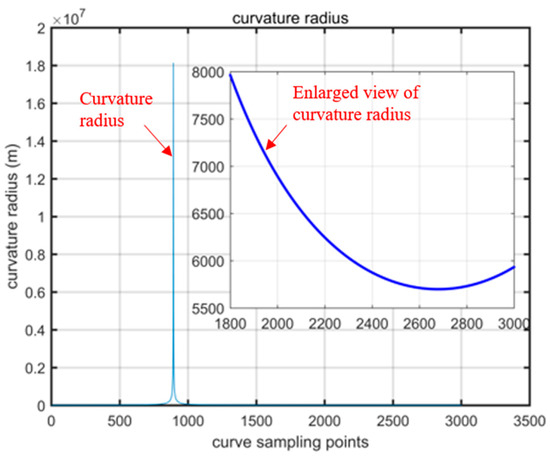
Figure 8.
Curvature radius of the curve.
From Figure 9, it can be observed that with GNSS position and velocity assistance, the position convergence is approximately 0.1 m. The heading misalignment angle also converges to around 0°, and as the curvature radius decreases, the convergence performance improves, as is evident in the latter part of the third subplot in Figure 10. As the processing was conducted with simulated data, the accelerometer bias estimates quickly converge to values near their true values.
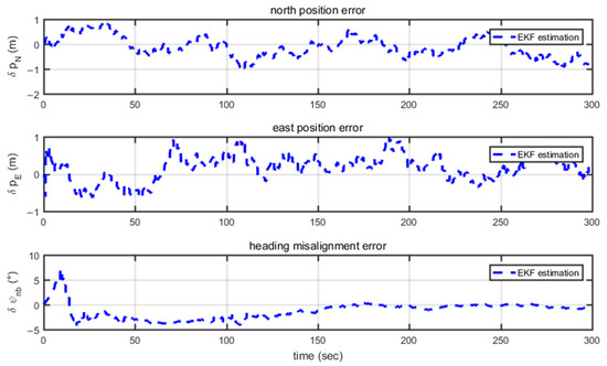
Figure 9.
Position and heading misalignment angle error.
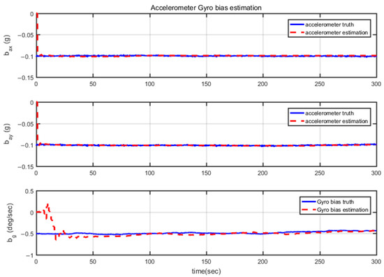
Figure 10.
Gyro and accelerometer bias estimation when the train passes through a curved section.
By examining the estimation results of the heading misalignment angle and inertial device biases in Figure 9, it can be observed that they converge to the set values of 0.1 g and 0.5°/s during curved track segments. This confirms the observability of heading during curved motion.
Finally, based on the theoretical analysis and simulation results presented earlier, it can be concluded that, when the train is moving at a constant speed on a straight track, GNSS velocity and heading updates can be used to avoid heading divergence and the unobservable gyro bias issue. Therefore, the simulation is set up as follows: the first 600 s utilize GNSS position and velocity assistance, the middle 600 s include both GNSS position and velocity assistance, and the last 600 s exclude velocity and heading assistance.
From Figure 11, it can be observed that, without heading assistance, position and velocity consistently converge. However, the heading misalignment angle rapidly di-verges in the first 600 s and approaches 180°. However, starting from 600 s, with GNSS velocity and heading assistance, not only is the heading misalignment angle estimated, as seen in Figure 12, but also the gyro bias quickly converges to around 0° as shown in Figure 13.
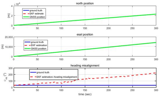
Figure 11.
Train’s position and heading misalignment estimation.
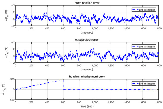
Figure 12.
Train’s position and heading misalignment error estimation.
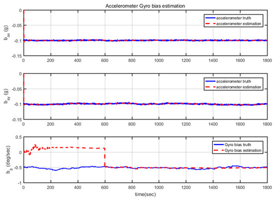
Figure 13.
Gyro and accelerometer bias estimation.
In the final 600 s, when GNSS velocity and heading assistance are turned off, navigation results are still maintained after compensating for the estimated gyro bias and heading misalignment angle. However, when GNSS velocity and heading assistance are triggered based on the track curvature and the yaw gyro measurement, the heading misalignment angle rapidly converges, and the gyro bias is accurately estimated.
Finally, after canceling GNSS velocity and heading assistance, the heading misalignment angle and gyro bias will remain in a slow divergence state.
4. Field Experiment
In the field experiment, onboard measuring sensors were used to collect data from Pontoise to Les grésillons, France. The environment is urban and open country, as de-pictured as Figure 14. Figure 15 shows the French SNCF train used for data acquisition. During the experiment, the train first stood still for five minutes to complete the initial alignment, and then, it was accelerated to maintain the speed at about 15 m/s, and at that time, the track was also straight, and the train maintained a constant speed and straight-line travel for 250 s. After that, acceleration and deceleration maneuvers were performed, and finally, the train was stopped for 300 s, as depicted in Figure 16.
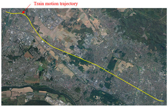
Figure 14.
Horizontal trajectory of a train-borne test conducted at Ermont–Pontoise in France.
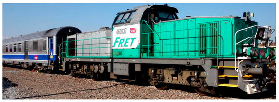
Figure 15.
Field test train used in this article.
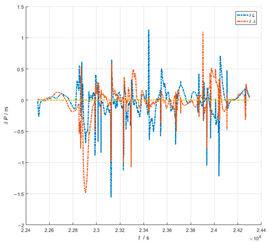
Figure 16.
Northeast position increment and position error.
The data processing process, using the given true value attitude as the reference attitude and then loosely combining GNSS and SINS, provides the position error results as shown in Figure 16. Then, from Figure 17, it can be seen that the heading error is slowly diverging during the 250 s of the train’s travel in a straight line at a constant speed, and it converges after the train’s subsequent entry into the acceleration and deceleration maneuvering phase, and it remains steadily converging in the final phase due to the sustained cornering, even though during this phase, the train is travelling at a constant speed. As shown in Figure 18, the train’s heading is slowly diverging, and then converging after the subsequent acceleration and deceleration maneuvers and entry into the curved segment.
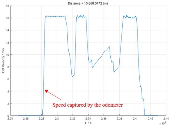
Figure 17.
Speed captured by the odometer while the train is running.
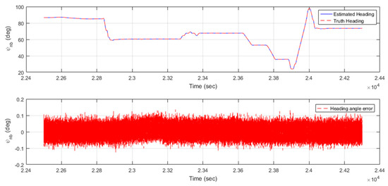
Figure 18.
Heading angle and heading angle error.
5. Conclusions
In this paper, the observability analysis theory is adopted to analyze the observability of the common operation modes of a train, and it is concluded that the heading angle and the heading gyro are not observable when the train is running in a straight line, while they are observable when it is accelerating and decelerating and passing through curved segments. Using this conclusion, simulation experiments were designed to provide a basis for device selection in the design of a SINS/GNSS system that meets train-positioning requirements. Whether the train is on a straight or curved track, the position estimation accuracy meets the simulation design criteria of 0.1 m, and the heading accuracy is higher than 0.25°. In comparison to the results of pure GNSS position and velocity-assisted navigation, where heading divergence occurs during constant velocity straight-line segments, the method proposed in this paper not only converges but also achieves accuracy comparable to that of GNSS velocity-based heading alignment.
Author Contributions
Conceptualization, W.C. and Y.T.; methodology, W.C.; software, W.C.; validation, W.C. and Y.T.; formal analysis, Y.T.; investigation, Y.T.; resources, G.Y.; data curation, W.C.; writing—original draft preparation, W.C.; writing—review and editing, Y.T.; visualization, W.C.; supervision, G.Y.; project administration, G.Y.; funding acquisition, Y.T. All authors have read and agreed to the published version of the manuscript.
Funding
This research was funded by China scholarship council (CSC), grant number 201906020135.
Institutional Review Board Statement
Not applicable.
Informed Consent Statement
Not applicable.
Data Availability Statement
No new data were created or analyzed in this study. Data sharing is not applicable to this article.
Conflicts of Interest
The authors declare no conflict of interest.
Appendix A. Models of Gyroscopes and Accelerometers
Gyroscopes and accelerometers are modeled as follows:
where is correlation time.
Assuming system noise , and measurement noise are Gaussian white noise. The system noise is as shown in Equation (A1).
Appendix B. F and G Matrices of System Equations
F and G matrices of system equations are organized as follows:
References
- Chen, D.; Wang, L.; Li, L. Position computation models for high-speed train based on support vector machine approach. Appl. Soft Comput. 2015, 30, 758–766. [Google Scholar] [CrossRef]
- Zhou, Y.; Chen, Q.; Wang, R.; Jia, G.; Niu, X. Onboard Train Localization Based on Railway Track Irregularity Matching. IEEE Trans. Instrum. Meas. 2022, 71, 9501013. [Google Scholar] [CrossRef]
- Jiang, S.; Deng, Z.; Liang, L.; Wang, Y.; Liu, J.; Zhang, H. Novel method to detect the speed and position of the HTS Maglev train by using the TMR sensor and the magnet arrays. Measurement 2023, 219, 113280. [Google Scholar] [CrossRef]
- Jiang, W.; Chen, S.; Cai, B.; Wang, J.; ShangGuan, W.; Rizos, C. A Multi-Sensor Positioning Method-Based Train Localization System for Low Density Line. IEEE Trans. Veh. Technol. 2018, 67, 10425–10437. [Google Scholar] [CrossRef]
- Otegui, J.; Bahillo, A.; Lopetegi, I.; Díez, L.E. A Survey of Train Positioning Solutions. IEEE Sens. J. 2017, 17, 6788–6797. [Google Scholar] [CrossRef]
- Jiang, W.; Yu, Y.; Zong, K.; Cai, B.; Rizos, C.; Wang, J.; Liu, D.; Shangguan, W. A Seamless Train Positioning System Using a Lidar-Aided Hybrid Integration Methodology. IEEE Trans. Veh. Technol. 2021, 70, 6371–6384. [Google Scholar] [CrossRef]
- Taylor, G.; Brunsdon, C.; Li, J.; Olden, A.; Steup, D.; Winter, M. GPS accuracy estimation using map matching techniques: Applied to vehicle positioning and odometer calibration. Comput. Environ. Urban Syst. 2006, 30, 757–772. [Google Scholar] [CrossRef]
- Huang, P.; Pi, Y.; Progri, I. GPS Signal Detection under Multiplicative and Additive Noise. J. Navig. 2013, 66, 479–500. [Google Scholar] [CrossRef]
- Li, Z.; Wang, R.; Gao, J.; Wang, J. An Approach to Improve the Positioning Performance of GPS/INS/UWB Integrated System with Two-Step Filter. Remote Sens. 2018, 10, 19. [Google Scholar] [CrossRef]
- Crespillo, O.G.; Medina, D.; Skaloud, J.; Meurer, M. In Tightly Coupled GNSS/INS Integration Based on Robust M-Estimators. In Proceedings of the 2018 IEEE/ION Position, Location and Navigation Symposium (PLANS), Monterey, CA, USA, 23–26 April 2018; pp. 1554–1561. [Google Scholar] [CrossRef]
- Liu, D.; Jiang, W.; Cai, B.; Wang, J.; Shangguan, W. A Tightly-Coupled GNSS/INS/MM Integrated System Based on Binary Search Algorithm for Train Localization Applications. In Proceedings of the 32nd International Technical Meeting of the Satellite Division of The Institute of Navigation (ION GNSS+ 2019), Miami, FL, USA, 16–20 September 2019; pp. 1272–1283. [Google Scholar] [CrossRef]
- Otegui, J.; Bahillo, A.; Lopetegi, I.; Díez, L.E. Evaluation of Experimental GNSS and 10-DOF MEMS IMU Measurements for Train Positioning. IEEE Trans. Instrum. Meas. 2019, 68, 269–279. [Google Scholar] [CrossRef]
- Marais, J.; Beugin, J.; Berbineau, M. A Survey of GNSS-Based Research and Developments for the European Railway Signaling. IEEE Trans. Intell. Transp. Syst. 2017, 18, 2602–2618. [Google Scholar] [CrossRef]
- Cai, Q.; Yang, G.; Quan, W.; Song, N.; Tu, Y.; Liu, Y. Error Analysis of the K-Rb-21Ne Comagnetometer Space-Stable Inertial Navigation System. Sensors 2018, 18, 670. [Google Scholar] [CrossRef]
- Tu, Y.; Yang, G.; Cai, Q.; Wang, L.; Zhou, X. Optimal design of SINS’s Stewart platform bumper for restoration accuracy based on genetic algorithm. Mech. Mach. Theory 2018, 124, 42–54. [Google Scholar] [CrossRef]
- Cai, Q.; Quan, W.; Xing, L.; Yang, G.; Song, N.; Tu, Y. Research on case rotating modulation for nuclear-spin comagnetometer in space-stable INS. Measurement 2019, 140, 388–394. [Google Scholar] [CrossRef]
- Tu, Y.; Yang, G.; Cai, Q.; Wang, L.; Yin, H. Dynamical analysis and experimental verification of deviation angles caused by rubber dampers deformation in high precision mechanically dithered RLG dual-axis RINS. Mech. Syst. Signal Process. 2019, 126, 553–567. [Google Scholar] [CrossRef]
- Wu, G.; Fang, X.; Song, Y.; Liang, M.; Chen, N. Study on the Shearer Attitude Sensing Error Compensation Method Based on Strapdown Inertial Navigation System. Appl. Sci. 2022, 12, 10848. [Google Scholar] [CrossRef]
- Zhao, B.; Zeng, Q.; Liu, J.; Gao, C.; Zhu, X.; Qiao, W. A Novel SINS/SRS/CNS Multi-Information Fusion Global Autonomous Navigation Method. Appl. Sci. 2022, 12, 10862. [Google Scholar] [CrossRef]
- Zhou, X.; Yang, G.; Niu, W.; Tu, Y. Precise Measurement and Compensation of the Micro Product of Inertia for Float Assembly in Pendulous Integrating Gyroscopic Accelerometers. Sensors 2023, 23, 1564. [Google Scholar] [CrossRef]
- Zhou, X.; Yang, G.; Niu, W.; Tu, Y. Analysis and Suppression of Nonlinear Error of Pendulous Integrating Gyroscopic Accelerometer at Instrument Level. Sensors 2023, 23, 1221. [Google Scholar] [CrossRef]
- Chen, Q.; Zhang, Q.; Niu, X. Estimate the Pitch and Heading Mounting Angles of the IMU for Land Vehicular GNSS/INS Integrated System. IEEE Trans. Intell. Transp. Syst. 2021, 22, 6503–6515. [Google Scholar] [CrossRef]
- Shen, C.; Zhang, Y.; Tang, J.; Cao, H.; Liu, J. Dual-optimization for a MEMS-INS/GPS system during GPS outages based on the cubature Kalman filter and neural networks. Mech. Syst. Signal Process. 2019, 133, 106222. [Google Scholar] [CrossRef]
- Yao, Y.; Xu, X.; Li, Y.; Zhang, T. A Hybrid IMM Based INS/DVL Integration Solution for Underwater Vehicles. IEEE Trans. Veh. Technol. 2019, 68, 5459–5470. [Google Scholar] [CrossRef]
- Liu, X.; Tang, J.; Shen, C.; Wang, C.; Zhao, D.; Guo, X.; Li, J.; Liu, J. Brain-like position measurement method based on improved optical flow algorithm. ISA Trans. in press. 2023. [CrossRef]
- Tang, Y.; Wu, Y.; Wu, M.; Wu, W.; Hu, X.; Shen, L. INS/GPS Integration: Global Observability Analysis. IEEE Trans. Veh. Technol. 2009, 58, 1129–1142. [Google Scholar] [CrossRef]
- Fan, C.; Hu, X.; He, X.; Tang, K.; Luo, B. Observability Analysis of a MEMS INS/GPS Integration System with Gyroscope G-Sensitivity Errors. Sensors 2014, 14, 16003–16016. [Google Scholar] [CrossRef]
- Zhang, Q. On stability of the Kalman filter for discrete time output error systems. Syst. Control. Lett. 2017, 107, 84–91. [Google Scholar] [CrossRef]
- Wang, P.; Li, W.; Wang, X.; Chu, X. The Method of Train Positioning Based on Digital Track Map Matching. MATEC Web Conf. 2018, 246, 03024. [Google Scholar] [CrossRef][Green Version]
- Lauer, M.; Stein, D. A Train Localization Algorithm for Train Protection Systems of the Future. IEEE Trans. Intell. Transp. Syst. 2015, 16, 970–979. [Google Scholar] [CrossRef]
- Veillard, D.; Mailly, F.; Fraisse, P. EKF-based state estimation for train localization. In Proceedings of the 2016 IEEE SENSORS, Orlando, FL, USA, 30 October–3 November 2016; pp. 1–3. [Google Scholar] [CrossRef]
- Abdolkarimi, E.S.; Mosavi, M.-R. A low-cost integrated MEMS-based INS/GPS vehicle navigation system with challenging conditions based on an optimized IT2FNN in occluded environments. GPS Solut. 2020, 24, 108. [Google Scholar] [CrossRef]
- Sun, Y.; Li, Z.; Yang, Z.; Shao, K.; Chen, W. Motion model-assisted GNSS/MEMS-IMU integrated navigation system for land vehicle. GPS Solut. 2022, 26, 131. [Google Scholar] [CrossRef]
- Li, W.; Liu, G.; Cui, X.; Lu, M. Feature-Aided RTK/LiDAR/INS Integrated Positioning System with Parallel Filters in the Ambiguity-Position-Joint Domain for Urban Environments. Remote Sens. 2021, 13, 2013. [Google Scholar] [CrossRef]
- Zhou, Y.; Chen, Q.; Niu, X. Kinematic Measurement of the Railway Track Centerline Position by GNSS/INS/Odometer Integration. IEEE Access 2019, 7, 157241–157253. [Google Scholar] [CrossRef]


Disclaimer/Publisher’s Note: The statements, opinions and data contained in all publications are solely those of the individual author(s) and contributor(s) and not of MDPI and/or the editor(s). MDPI and/or the editor(s) disclaim responsibility for any injury to people or property resulting from any ideas, methods, instructions or products referred to in the content. |
© 2023 by the authors. Licensee MDPI, Basel, Switzerland. This article is an open access article distributed under the terms and conditions of the Creative Commons Attribution (CC BY) license (https://creativecommons.org/licenses/by/4.0/).