Abstract
This paper presents a comprehensive design approach for a biconical log-periodic dipole array (Bi-log) hybrid antenna optimized specifically for electromagnetic interference (EMI) measurements. The antenna’s elements, scaling function, feed structure, balanced-to-unbalanced (Balun) geometry, and key parameter selection are carefully considered to achieve enhanced broadband testing capabilities. The proposed compact Bi-log hybrid antenna is optimized using Taguchi’s method within the frequency range of 30 MHz to 6 GHz. The optimization focuses on the discontinuity of the antenna factor (AF), incorporating miniaturized elements. The dimensions of the proposed antenna are minimized, with a length of 95 cm, width of 148.5 cm, height of 60 cm, and weight of 2.5 kg. Simulation results and experimental validations demonstrate its efficacy through comparison. Optimization results indicate that the voltage standing wave ratio VSWR < 2 (with 5 dB attenuator) and symmetry < ±0.5 dB also meet the regulatory standards according to ANSI C 63.4. This makes the proposed antenna suitable for use in various types of semi-anechoic chambers.
1. Introduction
Broadband antennas are widely used in electromagnetic interference (EMI) measurement systems. Many types of broadband antennas have been well-documented and applied for various aims, for example, biconical antenna, log-periodic dipole array (LPDA) antenna, biconical log-periodic dipole array (Bi-log) antenna, and horn antenna. Bi-log antennas are the most commonly used in practice tests and are used primarily as receiving antennas in radiation emission tests. The Bi-log antenna is a typical broadband antenna with complex geometry and is a hybrid antenna [1]. A hybrid antenna is defined as any constructed antenna that includes a combination of both broadband dipole elements and LPDA elements. Refs. [2,3] evaluated the structure of Bi-log antennas in 15 elements to cover the frequency range of 30 MHz to 1 GHz, but their operation bandwidth might exhibit a limitation when compared with conventional antennas. The impact of a ground plane and mutual coupling on the antenna factor (AF) was investigated using the Bi-log antenna in [4]. The paper provided information on the AF, an important parameter for EMI measurement with a receiving antenna in an electromagnetic field. Additionally, it is also defined as a key factor for characterizing antennas.
In recent years, many types of printed LPDA antennas have been developed to possess lightweight, low-cost, good directivity, and wide bandwidth properties [5,6,7,8,9]. Although the design of this antenna was uncomplicated, expanding it to cover broad frequency ranges and higher frequencies while maintaining a compact size could pose challenges. Abdulhameed et al. [5] presented a compact printed log-periodic biconical dipole array antenna that achieves size reduction, and bandwidth enhancement from 0.5 GHz to 6 GHz, but its feeding technique may result from undesired radiation during measurements. In [6], a compact bowtie-shaped dipole element of printed LPDA antenna is proposed for ultra-wideband application. Its lowest operation frequency was 0.5 GHz, and its average gain was only 6 dBi. A sinusoidal curve LPDA antenna with dielectric loading has been proposed in [7]. It has a bandwidth of 0.2 GHz to 0.8 GHz and a gain of 4.5 dBi. According to [8], the study introduced a printed LPDA antenna with a dual-band dipole element. The antenna has a compact size in terms of axial length, from 0.5 GHz to 10 GHz. Although the antenna gain was between 3 and 6.01 dBi, forming an array of 25 antenna elements could be a challenging issue. A compact planar LPDA antenna operating from 0.55 to 9 GHz within top-loading techniques with 50 elements array was proposed [9]. Its radiation patterns were not pointed in the direction of light, and its antenna gain ranged from 2.48 to 7.89 dBi. Additionally, the bandwidth of these antennas is not wide enough to cover 30 MHz and may not be suitable for EMI measurement. All of these antenna structures were also implemented on a lossy substrate, which affected both impedance matching and radiation efficiency. The balanced-to-unbalanced (Balun) is typically supplied as a part of the antenna for matching the wideband impedance. The analysis of the infinite Balun feed structure in [10] was exaggerated due to antenna asymmetry, which was resolved by decreasing the size of the feed.
For measurement applications, previous studies have extensively presented the causes of performance issues and problems of the broadband hybrid antenna in test environments of various sites [11,12,13,14,15]. Although these Bi-log antennas have been applied to achieve different purposes, little attention has been given to the evaluation of the comprehensive design of antenna optimization related to dimension, symmetry, and impedance match. The proposed structure in this paper is the combination of a bowtie and log-periodic to achieve a Bi-log hybrid antenna. The proposed antenna improves the reproducibility and consistency of a series of EMI measurements while significantly reducing measurement time. For cost-effective antenna design, the challenge of optimization design needs to be overcome by achieving uniform radiation characteristics, stable AF, and polarization rejection in a wide frequency range. The successful optimal design with Taguchi’s method [16] could be a potential approach for these achieving goals.
The Taguchi method has been adopted for effective optimization design in recent decades in industrial, scientific, and medical areas. Many scholars have conducted research with this method to optimize parameters of interest, such as for industrial manufacturing [17,18], neural networks [19,20,21], and medical applications [22,23,24], and it also can be employed in other areas [25,26,27]. Notably, the Taguchi method has consistently exhibited remarkable optimization capabilities. Transitioning from a traditional to an iterative process within Taguchi’s method [16,28] can establish it as a robust global optimization technique. Although Taguchi’s method has found widespread adoption in a variety of presented kinds of literature as above, it provides limited applications, particularly in the field of electromagnetism [29,30]. The Taguchi method has found application in the design of UWB antennas [28], slot antennas [31], dual-band/polarization patch antennas [32], antenna arrays [33,34,35], and even bandpass filters [36]. However, within the realm of broadband EMI measurement antenna design, the utilization of Taguchi’s method for antenna optimization has remained somewhat scarce. Despite the broad acceptance and implementation of Taguchi’s method across diverse types of literature, its application in electromagnetic contexts has been somewhat constrained. This is especially notable in the realm of broadband EMI measurement antenna design, where the adoption of Taguchi’s method for antenna optimization has been comparatively limited. However, in the realm of broadband EMI measurement antenna design, there have been relatively few instances where antennas have been crafted and fine-tuned through the application of Taguchi’s methodology.
This study proposes a significantly smaller and lighter broadband Bi-log hybrid antenna using a simple, fast, and accurate Taguchi’s method to analyze the impedance match and miniaturization. Our optimization design process follows Taguchi’s methodology, employing distinctive orthogonal arrays (OAs) to extract antenna parameters efficiently. It gathers comprehensive data from a limited set of experimental parameters. This approach encompasses the optimization of both element length and relative spacing to achieve selected proportionality factors, while also mitigating variations in radiated performance due to dimensional discrepancies. The proposed antenna uses Numerical Electromagnetics Code (NEC2) and Computer Simulation Technology (CST) Microwave for simulation and design, respectively. The antenna performance fully satisfies the antenna qualification conditions proposed by the ANSI C63.4 standard [37]. The measured results correspond well with the simulated data. This antenna not only confirms the validity and precision of the optimal design methodology but also contributes to its high sensitivity in EMI testing applications, ensuring accurate measurement results.
2. Antenna Configuration and Benchmark Performance
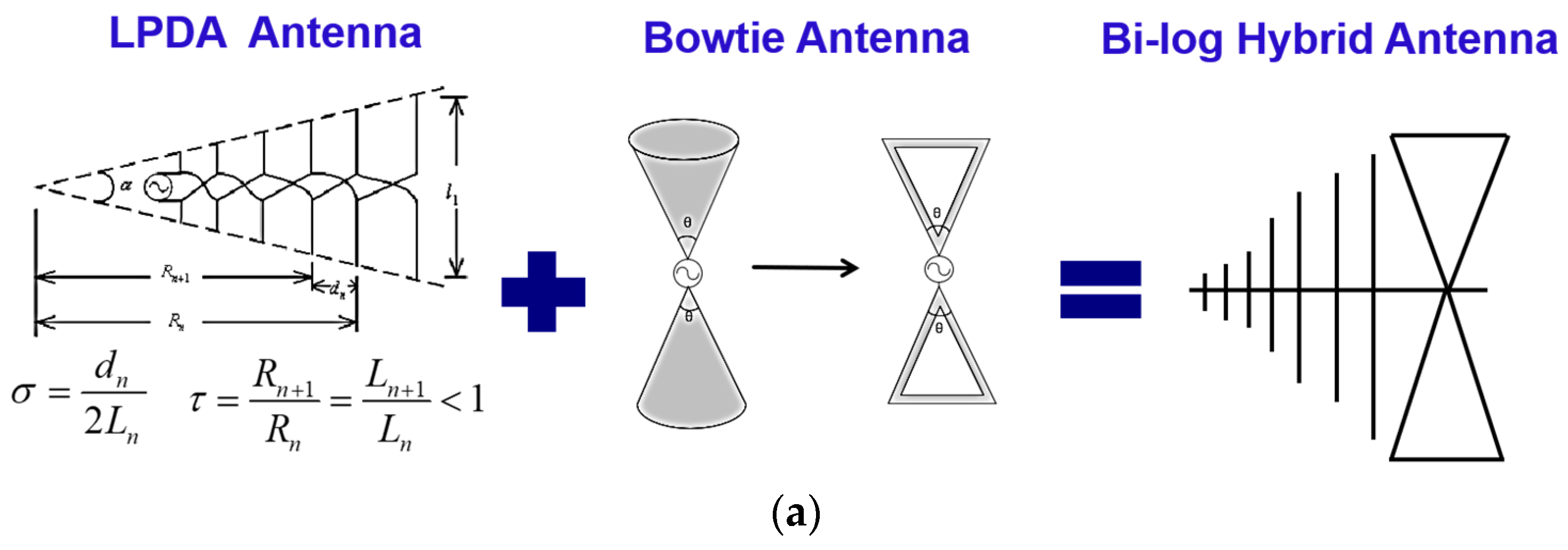
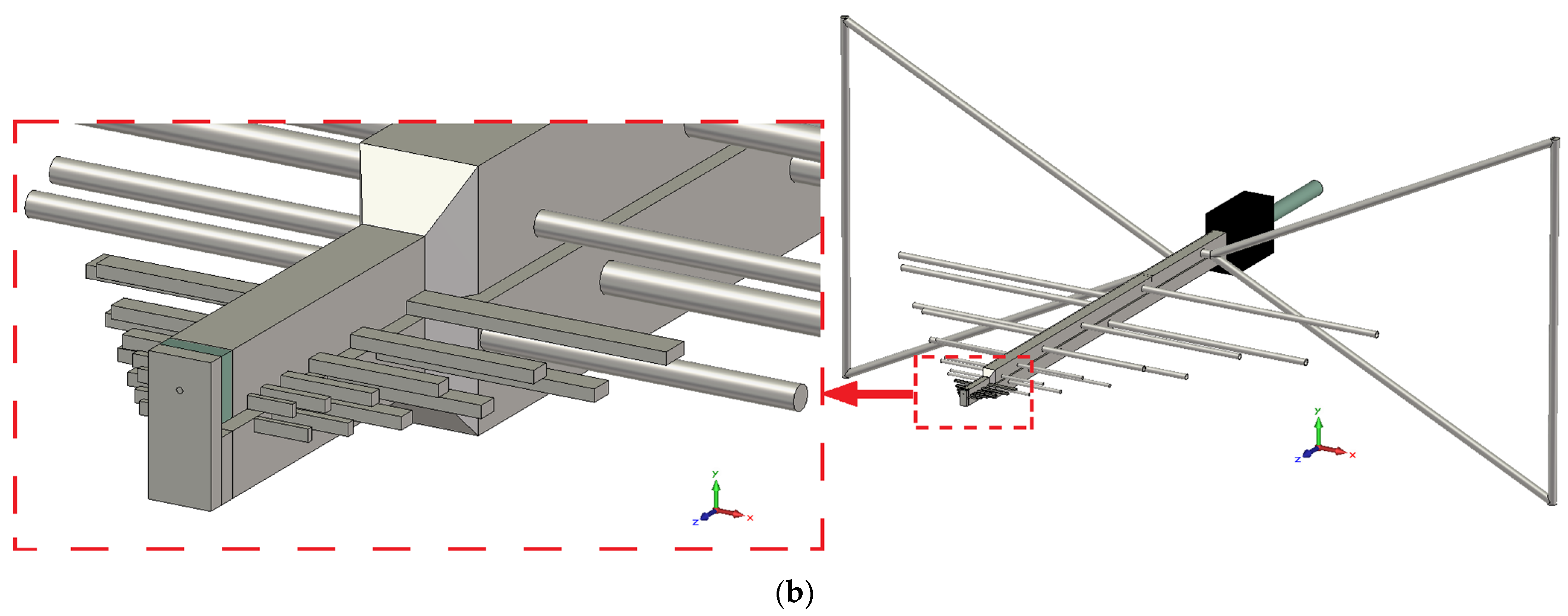
The Bi-log antenna has the favorable ability of receiving interference and wideband in radiation emission tests, due to its very good directivity characteristics and flat gain curve. Figure 1 depicts the main geometrical characteristics of the Bi-log antenna. This antenna consists of a set of LPDA antenna elements and a pair of bowtie antennas, as depicted in Figure 1a, and these two parts are connected together. The overview of the proposed Bi-log hybrid antenna is illustrated in Figure 1b. A planar bowtie and a compact LPDA element have been utilized to provide an optimal design, and they are based on the concept and method of broadband antenna theory for optimal designs. A part of the LPDA element in the Bi-log hybrid antenna describes the proportionality factors such as the scaling factor (τ), flare angle (α), and spacing factor (σ) for design parameters. After specifying two of the design parameters, the third parameter can be determined. The relationships between lengths, diameters, and spacings among elements are derived from directivity contour curves, which depend on τ for different values of σ. Another part of the antenna is the applied bowtie structure design. It depends on dimensions of its triangular shape and its flare angle values to obtain miniaturization, bandwidth, and impedance match performance. As mentioned above, the scope of the proposed antenna is attractive and provides many practical applications for EMI measurement.
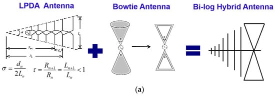

Figure 1.
Construction details of (a) LPDA antenna element and bowtie antenna; (b) overview of the proposed Bi-log hybrid antenna.
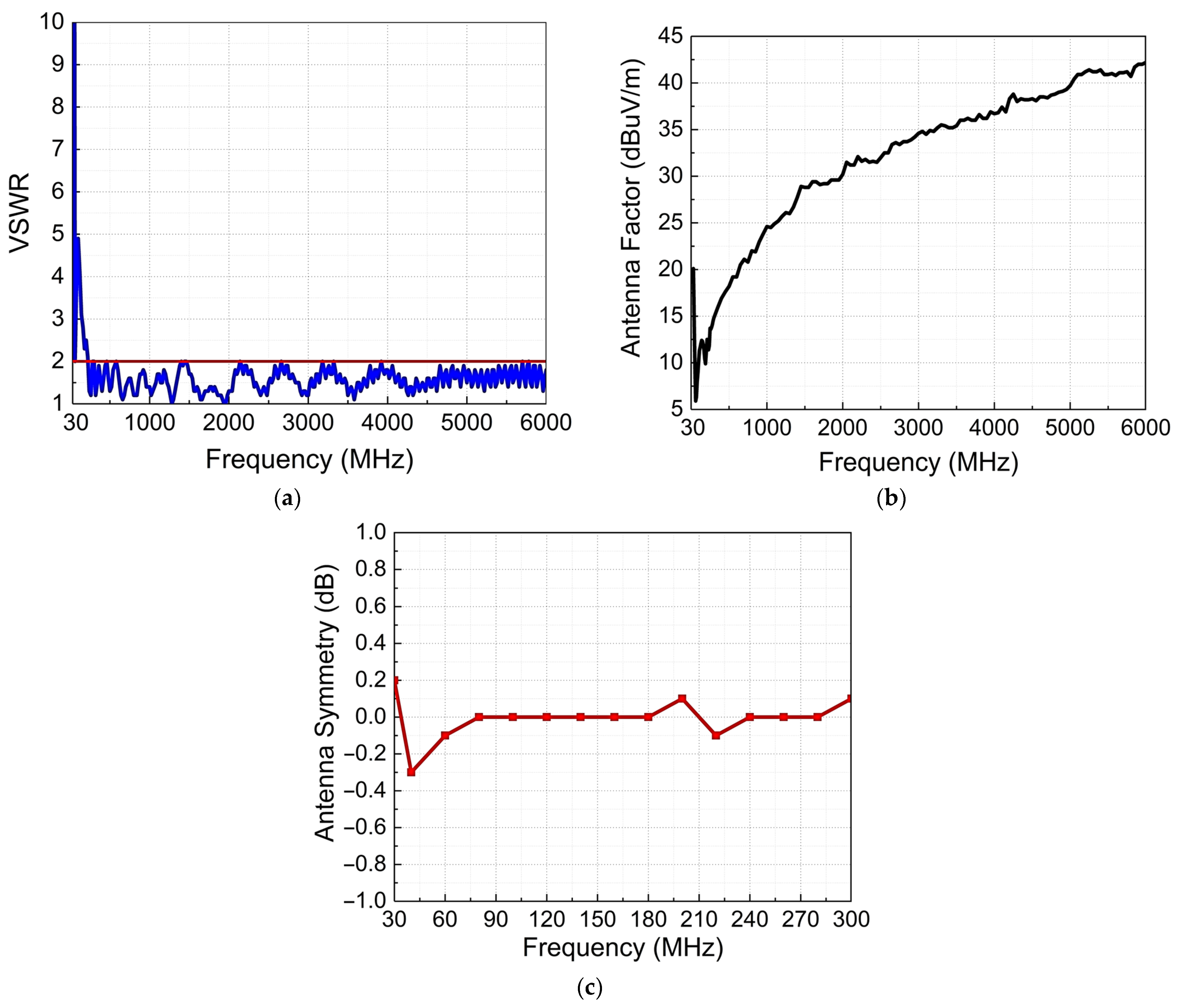
Figure 2 illustrates the performance benchmark for the proposed antenna. As shown in Figure 2a, the impedance matching band is wide enough to cover the 30 MHz to 6 GHz range, without the attenuator. In the purposed acceptance conditions in the whole bands, the voltage standing wave ratio (VSWR) is below two while the AF is stable and linear, as demonstrated in Figure 2b. The ratio of antenna symmetry has an up and side-down measurement setup, respectively, in vertical polarization. It provides a slight deviation of 0.5 dB with a small gain variation, as shown in Figure 2c. The remarkable performance of the antenna is also summarized in Table 1. This table determines several items such as the antenna type, operation frequency band, number of antenna elements, scaling factor (τ), fractional bandwidth (FBW), and gain by observing and comparing variation, respectively. Furthermore, the overall dimensions of the proposed antenna can be as small as 95 cm (L) by 148.5 cm (W) by 60 cm (H), and it can be as lightweight as 2.5 kg. The proposed antenna demonstrates outstanding performance, surpassing previously published works in optimized design of antennas. Furthermore, it boasts a high antenna gain and covers a broader frequency range, as shown in Table 1.
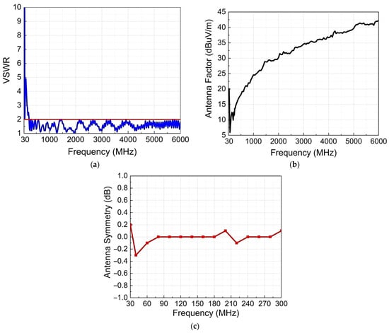
Figure 2.
Benchmark performance of the proposed antenna: (a) VSWR, (b) antenna factor, and (c) antenna symmetry.

Table 1.
Comparison of the published antennas.
3. Antenna Optimization using Taguchi’s Method
The Taguchi method also has proven effective in the realm of antenna design, contributing to the creation and development of this study. It compares the results of the simulated experiments with the orthogonal table and those with the response table and then keeps the better result for the next iteration that is required to be performed. The multi-objective optimization leads to the optimum dipole lengths, spacings between the dipoles, and dipole wire diameters. During the optimal process, the orthogonal tables obtain better experimental data with fewer experiments and gradually in a systematic way converge the search range.
3.1. Concepts of Taguchi’s Method
In general, the concept of optimization of antenna design procedures includes several steps such as determining the parameters and frequency ranges of the proposed antenna, using Taguchi’s method with an OA for simulations, establishing the frequency response condition, reducing the searching range iteratively, and repeating the simulations to achieve convergence. The Taguchi method yields better antenna parameters of impedance match, and the desired directive pattern is compared with traditional trial and error approaches.
To achieve a better combination of parameter values, it is necessary to utilize the benefits of OAs. As mentioned earlier, it offers an efficient method for identifying the optimal parameters of a general optimization problem. The notation OA(N,k,s,t) is usually used to represent an OA of N rows and k columns (for k parameters) with s levels and strength t. In Table 2, the OA table (L27 310) determines varying τ values as 10 control factors, with three levels, only 27 experiments are needed to find a better combination of parameter values. In 27 runs of the experiment, which are dramatically less than 310, a full factorial strategy is used instead. The established frequency response condition of the cost function Xi is nominal-the-best. The value was calculated from experimental data using the simulation result, which satisfies the good impedance matching condition as VSWR < 2. The signal-to-noise ratio (SNR) is also obtained from the average of the cost function value (calculated).
Table 2.
Orthogonal array table (L27 310) for optimization of antenna design.
The higher number of antenna elements required in the whole band depends on the physical dimensions of the antenna and the greater values of τ. The ratio of the longest element length to the second longest element length is called τ1. τ2, τ3, τ4, and so on, and they are also ratios of every adjacent element length. The key parameter for optimizing antenna performance is τ. The initial search ranges of τ values are preset as 0.76 to 0.84 with three levels, which makes it much easier to implement this efficient approach. This is because each level of a factor is represented an equal number of times, and if one factor is held constant, the other factors’ levels are also equally represented. This promotes fairness and objectivity in evaluating the frequency response of each factor level. Therefore, the obtained antenna parameter achieves the desired frequency response with fewer iterations to reach the optimum solutions in an equally distributed fractional factorial experiment.
3.2. Optimization of Antenna Design
The Bi-log hybrid antenna has been presented and optimized, which is made up of a combination of bowtie and LPDA antenna parts. Using proper geometry, the bowtie part of the proposed antenna achieves small dimensions at lower frequencies. The LPDA part determines the antenna properties at higher frequencies, typically over 200 MHz. To optimize the design of an LPDA part, attention must be paid to the directivity of radiation patterns and the impedance characteristics within the operating frequency ranges. The LPDA part of this antenna, in physical size and gain, are defined by the constants τ and σ. Larger values result in longer antennas with more elements and gain. The optimization focuses on impedance matching, stable gain, continuity of the AF, and incorporation of miniaturized elements. The optimal design was determined with a series τ of the key parameters and in the frequency range from 30 MHz to 6 GHz. The analysis uses Taguchi’s method with an OA to obtain results from simulations using NEC2 and CST software. The established frequency response conditions of the cost function Xi and SNR are nominal-the-best as VSWR < 2, which are obtained from the formula represented in Equations (1) and (2). It also iteratively reduces the search range and repeats the simulations to achieve convergence. Simulation results are used to determine optimal matching parameters for the proposed antenna configuration.
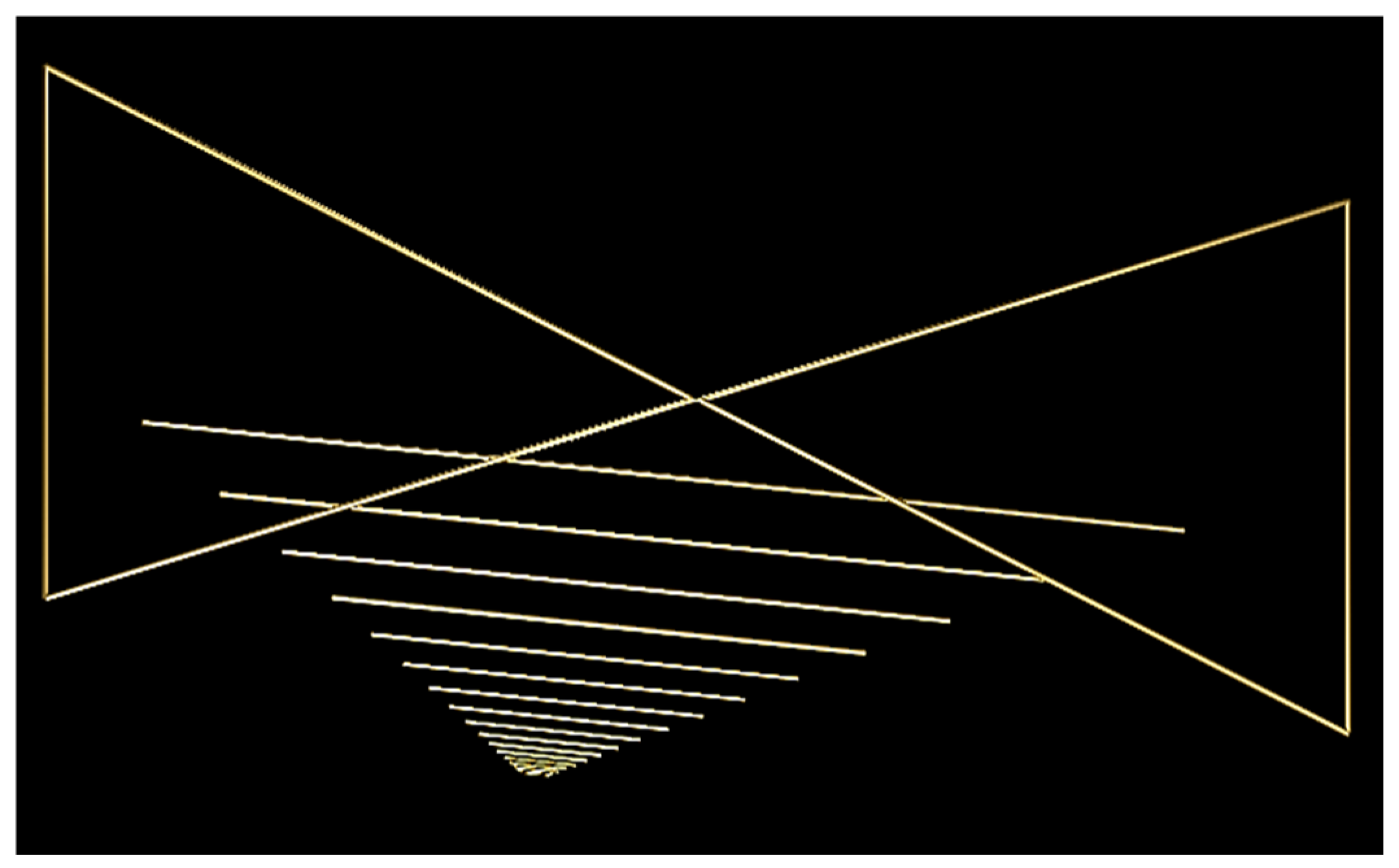
The numerical model of a Bi-log hybrid antenna used in the NEC2 simulation is shown in Figure 3. The initial parameters for the dipole elements and their spacing in the proposed optimal antenna design are obtained through the use of NEC2 simulation. The characteristic impedance of the dipole element can be adjusted by changing its length and width. This model is composed of 267 segments, and the elements of the antenna are connected to each other by transmission lines. Following the optimization of the Taguchi method and a standard OA table, the details of the antenna element are presented in Table 3. The LPDA antenna has 21 sets of broadband antenna units, which consist of 11 planar plates (2000–6000 MHz) and 10 cylindrical dipoles (200–2000 MHz). Both types of LPDA elements were under the same procedure with optimal design, respectively. The spacing factor σ of LPDA elements is 0.06 compared to the relative spacing of each element. The τ values of the planar plate dipole of LPDA elements are 0.796, 0.806, 0.798, 0.792, 0.803, 0.800, and 0.825. The scale factor τ of the cylindrical dipole of LPDA elements are 0.770, 0.787, 0.792, 0.759, 0.803, 0.798, 0.792, 0.800, and 0.840.
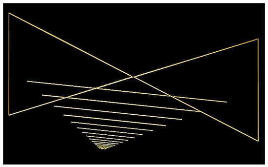
Figure 3.
The numerical model of analyzed Bi-log hybrid antenna with NEC2.
Table 3.
Optimized dimensions of the proposed Bi-log hybrid antenna.
Achieving an optimal performance for the proposed antenna depends on the meticulous design of its LPDA elements, which has been elaborated upon earlier. The antenna booms are parallel two-wire transmission lines that affect the length of each element for impedance matching. Therefore, the relationship among the input impedance (R0) of 50 ohms, the average characteristic impedance of the dipole element (Za), and the impedance of the transmission line (Z0) has been investigated. The nominal input impedance of the proposed antenna is 50 ohms. A constant radius of dipole element has been utilized to make construction easier. The characteristic impedance of Z0 is fixed at 120 ohms for planar plate elements on a 10 mm square aluminum tube and 150 ohms for cylindrical dipole elements on a 19 mm square aluminum tube, respectively. To achieve practical antenna designs, dipole diameters of cylindrical elements are grouped into four categories of 4 mm, 5 mm, 7 mm, and 9 mm, while planar plate elements with widths of 1–5 mm.
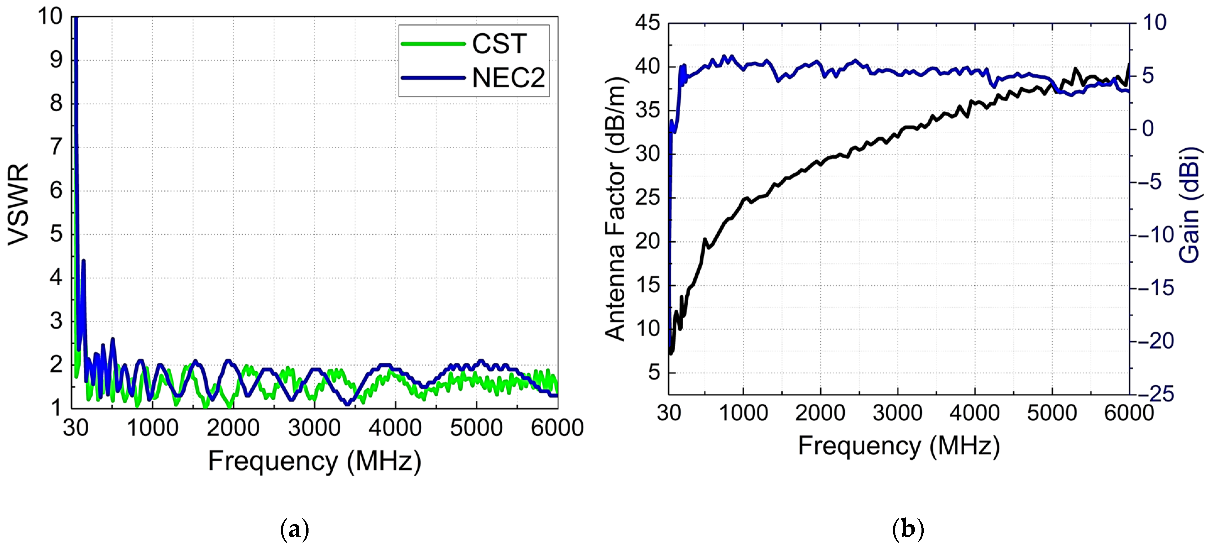
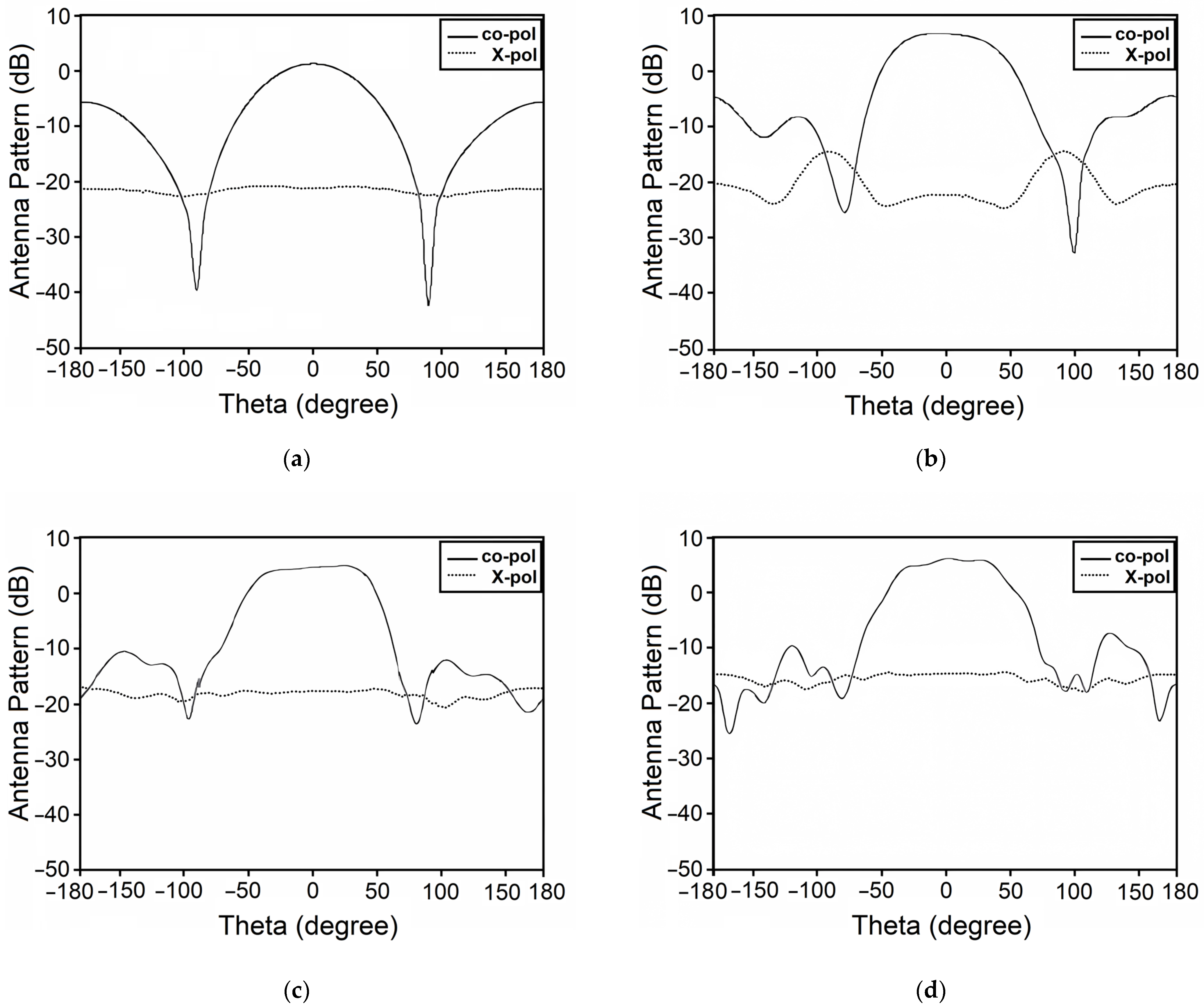
In addition, a low-frequency antenna unit is made up of a bowtie antenna set that evolves from the biconical structure. This type of antenna is one of the few antennas that can use mathematical derivation to analyze its working principle. The impedance (real part and imaginary part) of the antenna can be derived to design a bowtie structure. The trade-off from the flare angle is relatively uniform in terms of the real part, imaginary part, and VSWR and conforms to the broadband characteristics. The best performance is achieved with the bowtie element, which has a 52° flare angle and a triangle height of 60 cm. All of these elements are mounted on either side of a parallel metal boom. The well-designed LPDA and bowtie could be then integrated. The performance of the integrated antenna is shown in Figure 4. Within the considered frequency band, the antenna demonstrates well the impedance matching, a linear AF, and a consistently flat gain curve. Figure 5 shows the simulated radiation patterns with good directivity characteristics. Accordingly, the Taguchi method significantly outperforms the previous method in optimizing antenna configurations for these two parts.
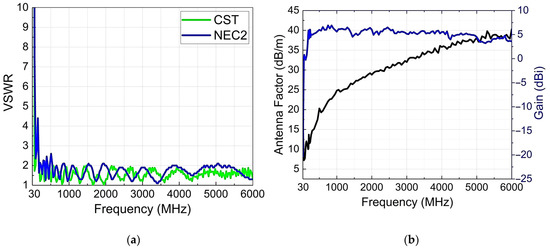
Figure 4.
Simulated result of the (a) VSWR; (b) antenna factor and gain.
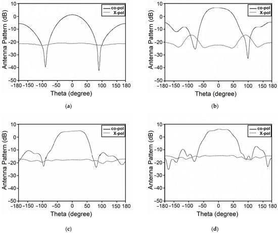
Figure 5.
Simulated result of antenna patterns: (a) 200 MHz, (b) 500 MHz, (c) 1000 MHz, and (d) 2000 MHz.
3.3. Feed Structure and Balun
The design of the feed structure and Balun are essential for achieving the best performance of the proposed antenna. The optimized antenna not only considers the antenna structure and the elements but also needs to determine the characteristic impedance of the transmission line of feeds. The proposed structure of feed includes a wideband Balun for balancing improvement, an L-shape feeding structure for uniform current distribution, and a tapered offset spacing over transmission lines for each element placement. A more reliable and complete antenna configuration has been considered within the proposed Balun and feeding structure design using the CST simulation.
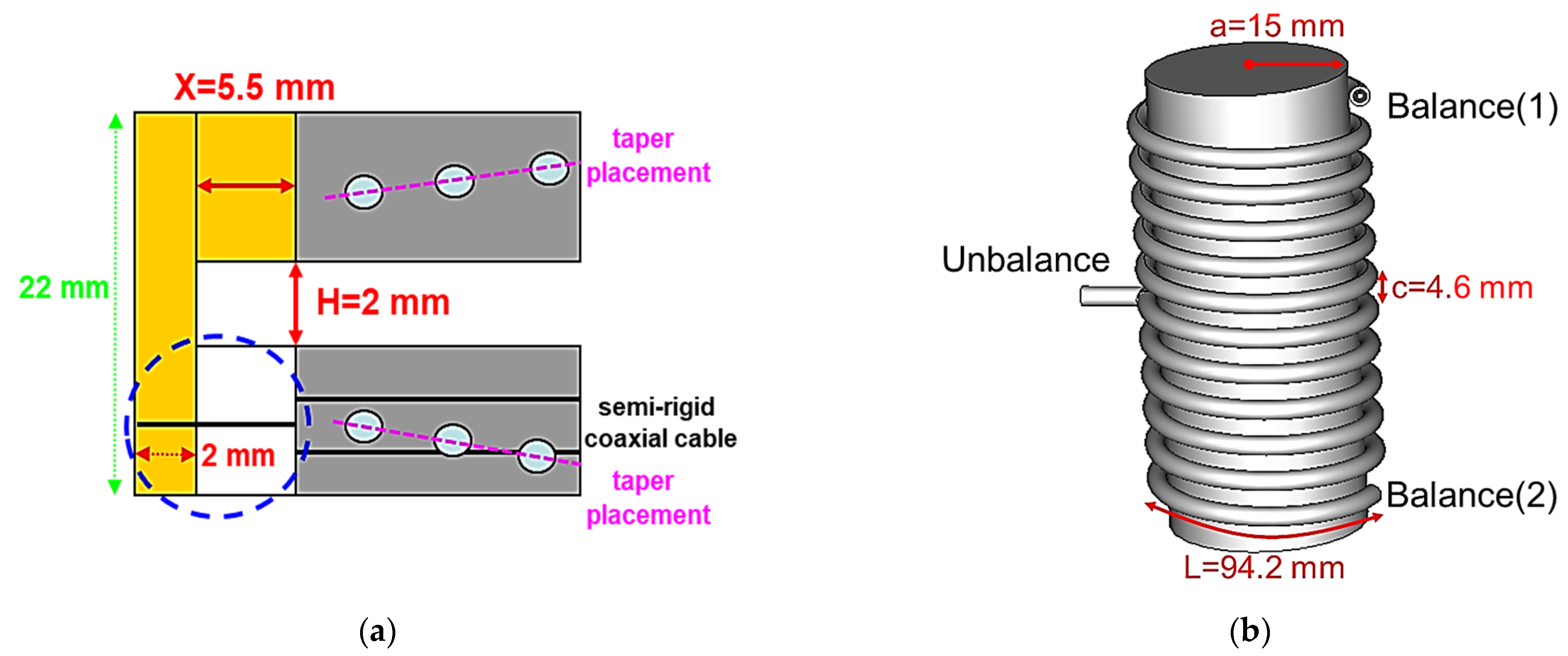
The L-shape feed structure with two variable parameters of X (5.5 mm) and H (2 mm), as depicted in Figure 6a on the tip of the antenna, also presented the tapered configuration of each spacing over the booms. To attain this balance symmetry capability, quasi-air coil Balun with a bound of five as a 1:1 turn is utilized at the antenna’s feed point. It offers the essential wideband matching and proper current phase for the elements, effectively covering the frequency range of 30 MHz to 200 MHz. In Figure 6b, the proposed Balun is an indispensable device for antenna-feed networks. It connects a balanced two-conductor port to an unbalanced port through a semi-rigid coaxial cable, where the radius a is 15 mm, spacing c is 4.6 mm, circumference L is 94.2 mm, and the total height is 60 mm. Figure 7 shows the simulated result of the real part (solid red line) and imaginary part (dot blue line) of Balun impedance. The Balun operates effectively across a wide frequency range and optimizes antenna performance. The proposed Balun not only reduces the unbalanced current on the surface of the feeding cable but also ensures accurate radiation characteristics of the bowtie part of the antenna in wideband. The structure can be easily configured on this antenna through the feeding cable directly without adding any extra components such as a matching circuit or transformer. The results confirm that the proposed Balun is suitable for the Bi-log hybrid antenna. Its feeding technique for this antenna has low design complexity and is easier to implement than traditional antennas.
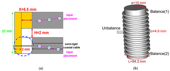
Figure 6.
Antenna feeding structure (a) on the front end (side view) and (b) Balun geometry.
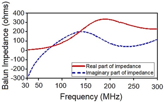
Figure 7.
Simulated result of the Balun impedance.
4. Antenna Implementation and Measurement
The fabricated Bi-log hybrid antenna of the prototype is shown in Figure 8a. This antenna prototype was measured on an open area test site (OATS) in which the ground plane size is 50 m (L) by 40 m (W), as shown in Figure 8b. The measuring system is based on the standard site method and applies a three-antenna method for the test. The AF affects the magnitude of the received signal in the EMI test that offers the correlation between the calibrated values in different distance conditions. Its performance has been evaluated with and without the 5 dB attenuator on the terminal of the proposed antenna during the 10 m test range. The measured results of AF and antenna efficiency are displayed in Figure 9a,b, respectively. To ensure accurate and reliable EMI measurements, it has become a norm to assess the isolation between different polarizations in linear antennas. The measurement errors depend on the contribution of cross-polarization rejection curves. The cross-polarization rejection from 200 MHz to 2000 MHz is shown in Figure 10. The bandwidth selection was based on the requirements of ETS-Lindgren 3106B’s high-precision double-ridged guide antenna for cross-polarization measurement techniques. The maximum cross-polarization rejection of the proposed antenna is 10 dB. In addition, based on the comparison of Figure 2 and Figure 4, the achievements of antenna performance are a VSWR of <2.0, stable and linear AFs, and antenna symmetry of <±0.5 dB. The measured results are in good agreement with the simulated ones, thereby validating the design and confirming its performance. Furthermore, this proposed antenna is ideal for conducting EMI measurements due to its ability to cover a broad range of frequencies from 30 MHz to 6 GHz, while still being small and compact. The antenna can be used for EMI testing in various types of semi-anechoic chambers, including 1 m, 3 m, and 10 m configurations, which are required to conform to the ANSI C63.4 standard for test procedures and antenna specifications.
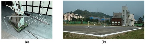
Figure 8.
Photographs of the proposed antenna: (a) the prototype and (b) the measurement setup in an OATS.
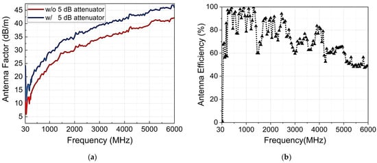
Figure 9.
Measured result of the (a) antenna factor with and without 5 dB attenuator and (b) antenna efficiency.

Figure 10.
Measured cross-polarization rejection.
5. Conclusions
A novel broadband Bi-log hybrid antenna using Taguchi’s method has been presented as a global optimization design. The antenna has a linear, continuous, and stable AF, exhibiting a good flatness in the frequency range of 30 MHz to 6 GHz. The FBW is as large as 198%. The optimization of antenna performance is achieved with a VSWR of <2, a 5 dB attenuator, and a symmetry of <±0.5 dB. This antenna consists of a bowtie and an LPDA structure that are fed with a taper placement on each boom side and a quasi-air coils wideband Balun feeding is achieved. The design concepts of the proposed antenna and its feeding structure have been well introduced. The antenna with the least number of elements, i.e., 21, is used to cover the specified bandwidth. The antenna with compact size and is lightweight results in the directive patterns of constant gain, while occupying a dimension that is reduced by more than 12%. This can also lead to reduced costs of fabrication and materials used, especially in mass production. It also highly satisfies the specifications of regulatory standards proposed by ANSI C 63.4, especially for EMI measurement antenna applications. Since most electromagnetic interference problems are highly complex, the proposed antenna with optimal design is used to quickly obtain accurate test results for EMI measurement.
Author Contributions
Conceptualization, C.-H.L. and D.-B.L.; methodology, C.-H.L. and D.-B.L.; software, C.-H.L.; validation, C.-H.L.; formal analysis, C.-H.L.; investigation, C.-H.L.; resources, D.-B.L.; data curation, C.-H.L.; writing—original draft preparation, C.-H.L.; writing—review and editing, C.-H.L.; visualization, C.-H.L.; supervision, D.-B.L.; project administration, D.-B.L.; funding acquisition, D.-B.L. All authors have read and agreed to the published version of the manuscript.
Funding
The authors declare that no funds, grants, or other support were received during the preparation of this manuscript.
Institutional Review Board Statement
Not applicable.
Informed Consent Statement
Not applicable.
Data Availability Statement
Not applicable.
Conflicts of Interest
The authors declare no conflict of interest.
References
- Porter, S.J.; Marvin, A.C. A New Broadband EMC Antenna for Emissions and Immunity. In Proceedings of the EMC’94 Roma International Symposium on Electromagnetic Compatibility, Rome, Italy, 13–16 September 1994; pp. 75–79. [Google Scholar]
- Bittera, M.; Smiesko, V.; Kovac, K.; Hallon, J. Directional properties of the Bilog antenna as a source of radiated electromagnetic interference measurement uncertainty. IET Microw. Antennas Propag. 2010, 4, 1469–1474. [Google Scholar] [CrossRef]
- Bittera, M. Modeling broadband wire antennas with complex geometry. Procedia Eng. 2014, 69, 1082–1087. [Google Scholar] [CrossRef]
- Chen, H.-F.; Lin, K.-H. A numerical analysis of antenna factor of bilog antennas for normalized site attenuation and EMC measurement. In Proceedings of the 2003 IEEE Symposium on Electromagnetic Compatibility. Symposium Record (Cat. No.03CH37446), Boston, MA, USA, 11–16 May 2003; pp. 817–821. [Google Scholar]
- Abdulhameed, A.A.; Kubík, Z. Design a Compact Printed Log-Periodic Biconical Dipole Array Antenna for EMC Measurements. Electronics 2022, 11, 2877. [Google Scholar] [CrossRef]
- Donelli, M.; Manekiya, M.; Mulloni, V.; Marchi, G.; Mendicino, R. A Compact Ultra-Wide Band Printed Log-Periodic Antenna Using a Bow-Tie Structure. Prog. Electromagn. Res. C 2022, 124, 43–52. [Google Scholar] [CrossRef]
- Chang, L.; He, S.; Zhang, J.Q.; Li, D. A compact dielectric-loaded Log-Periodic Dipole Array (LPDA) antenna. IEEE Antennas Wirel. Propag. Lett. 2017, 16, 2759–2762. [Google Scholar] [CrossRef]
- Anim, K.; Jung, Y.-B. Shortened log-periodic dipole antenna using printed dual-band dipole elements. IEEE Trans. Antennas Propag. 2018, 66, 6762–6771. [Google Scholar] [CrossRef]
- Kyei, A.; Sim, D.U.; Jung, Y.B. Compact log-periodic dipole array antenna with bandwidth enhancement techniques for the low frequency band. IET Microw. Antennas Propag. 2017, 11, 711–717. [Google Scholar] [CrossRef]
- McLean, J.S. Asymmetry in Log-Periodic Dipole Antennas and Hybrid Antennas due to the Infinite Balun. In Proceedings of the 2020 IEEE International Symposium on Electromagnetic Compatibility & Signal/Power Integrity (EMCSI), Reno, NV, USA, 27–31 July 2020; pp. 67–72. [Google Scholar]
- Chen, Z.C. Understanding the measurement uncertainties of the bicon/log hybrid antenna. ITEM 1999 1999. Available online: https://api.semanticscholar.org/CorpusID:107667301 (accessed on 20 October 2023).
- Bittera, M.; Kovac, K.; Smiesko, V.; Hallon, J. Influence of Directivity Pattern of Bilog Antenna to Radiated EMI Measurement Uncertainty. In Proceedings of the 2008 14th Conference on Microwave Techniques, Prague, Czech Republic, 23–24 April 2008; pp. 1–4. [Google Scholar]
- Blas, L.S.; Dominguez, F.M.; Gatti, E. Performance of broadband hybrid antennas for EMC measurements. In Proceedings of the 2016 IEEE Global Electromagnetic Compatibility Conference (GEMCCON), Mar del Plata, Argentina, 7–9 November 2016; pp. 1–3. [Google Scholar]
- Makino, I.; Okuyama, S.; Shimanoe, H.; Muramatsu, H. Comparison experiments on hybrid and biconical/LPD antennas in radiated emission measurement below 1 GHz. In Proceedings of the 2015 Asia-Pacific Symposium on Electromagnetic Compatibility (APEMC), Taipei, Taiwan, 25–29 May 2015; pp. 596–599. [Google Scholar]
- Bittera, M.; Hallon, J.; Szolik, I.; Hartansky, R. Alternative Approach Leading to Reduction in Measurement Instrument Uncertainty of EMI Measurement. Meas. Sci. Rev. 2023, 23, 64–71. [Google Scholar] [CrossRef]
- Taguchi, G.; Chowdhury, S.; Wu, Y. Taguchi’s Quality Engineering Handbook; Wiley: New York, NY, USA, 2005. [Google Scholar]
- Antony, J.; Antony, F.J. Teaching the Taguchi method to industrial engineers. Work. Study 2001, 50, 141–149. [Google Scholar] [CrossRef]
- Unal, R.; Dean, E.B. Taguchi approach to design optimization for quality and cost: An overview. In Proceedings of the 1991 Annual Conference of the International Society of Parametric Analysts, New Orleans, LA, USA, 21–24 May 1991. [Google Scholar]
- Khaw, J.F.; Lim, B.S.; Lim, L.E. Optimal design of neural networks using the Taguchi method. Neurocomputing 1995, 7, 225–245. [Google Scholar] [CrossRef]
- Yang, S.M.; Lee, G.S. Neural network design by using Taguchi method. J. Dyn. Syst. Meas. Control 1999, 121, 560–563. [Google Scholar] [CrossRef]
- Tortum, A.; Yayla, N.; Çelik, C.; Gökdağ, M. The investigation of model selection criteria in artificial neural networks by the Taguchi method. Phys. A: Stat. Mech. Its Appl. 2007, 386, 446–468. [Google Scholar] [CrossRef]
- Taner, T.; Antony, J. Applying Taguchi methods to health care. Leadersh. Health Serv. 2006, 19, 26–35. [Google Scholar] [CrossRef] [PubMed]
- Tseng, H.-C.; Lin, H.-C.; Tsai, Y.-C.; Lin, C.-H.; Changlai, S.-P.; Lee, Y.-C.; Chen, C.-Y. Applying Taguchi Methodology to Optimize the Brain Image Quality of 128-Sliced CT: A Feasibility Study. Appl. Sci. 2022, 12, 4378. [Google Scholar] [CrossRef]
- Rahman, M.A.; Chandren Muniyandi, R.; Albashish, D.; Rahman, M.M.; Usman, O.L. Artificial neural network with Taguchi method for robust classification model to improve classification accuracy of breast cancer. PeerJ Comput. Sci. 2021, 7, e344. [Google Scholar] [CrossRef] [PubMed]
- Nai, S.E.; Lei, Z.; Wong, S.H.; Chew, Y.H. Optimizing radio network parameters for vertical sectorization via Taguchi’s method. IEEE Trans. Veh. Technol. 2016, 65, 860–869. [Google Scholar] [CrossRef]
- Awada, A.; Wegmann, B.; Viering, I.; Klein, A. Optimizing the radio network parameters of the long term evolution system using Taguchi’s method. IEEE Trans. Veh. Technol. 2011, 60, 3825–3839. [Google Scholar] [CrossRef]
- Zaman, M.A.; Matin, M.A. Optimization of Jiles-Atherton hysteresis model parameters using Taguchi’s method. IEEE Trans. Magn. 2015, 51, 1–4. [Google Scholar] [CrossRef]
- Weng, W.C.; Yang, F.; Elsherbeni, A.Z. Electromagnetics and Antenna Optimization Using Taguchi’s Method; Morgan & Claypool: San Rafael, CA, USA, 2007. [Google Scholar]
- Weng, W.C.; Yang, F.; Demir, V.; Elsherbeni, A. Optimization using Taguchi method for electromagnetic applications. In Proceedings of the 2006 First European Conference on Antennas and Propagation, Nice, France, 6–10 November 2006; pp. 1–6. [Google Scholar]
- Weng, W.C.; Yang, F.; Elsherbeni, A.Z. Linear antenna array synthesis using Taguchi’s method: A novel optimization technique in electromagnetics. IEEE Trans. Antennas Propag. 2007, 55, 723–730. [Google Scholar] [CrossRef]
- Weng, W.C.; Choi, C.T.M. Optimal design of CPW slot antennas using Taguchi’s method. IEEE Trans. Magn. 2009, 45, 1542–1545. [Google Scholar] [CrossRef]
- Ko, J.-H.; Byun, J.-K.; Park, J.-S.; Kim, H.-S. Robust design of dual band/polarization patch antenna using sensitivity analysis and Taguchi’s method. IEEE Trans. Magn. 2011, 47, 1258–1261. [Google Scholar] [CrossRef]
- Smida, A.; Azizi, M.K.; Ghayoula, R.; Gharsallah, A. Synthesis of Phased of conformal Cylindrical Arc Antenna Arrays referring to Taguchi Method. In Proceedings of the IEEE International Conference on Multimedia Computing and Systems (ICMCS), Marrakech, Morocco, 14–16 April 2014; pp. 1333–1337. [Google Scholar]
- Smida, R.G.; Nemri, N.; Trabelsi, H.; Gharsallah, A.; Grenier, D. Phased Arrays in Communication System based on Taguchi- Neural Networks. Int. J. Commun. Syst. 2013, 27, 4449–4466. [Google Scholar] [CrossRef]
- Mandava, S.; Ram, G.; Kumar, G.A. Synthesis of Conformal Phased Array Antenna with Improved SLL. In Proceedings of the 2022 IEEE Microwaves, Antennas, and Propagation Conference (MAPCON), Bangalore, India, 12–15 December 2022; pp. 1027–1031. [Google Scholar]
- Weng, W.-C. Design and Optimization of Compact Microstrip Wideband Bandpass Filter Using Taguchi’s Method. IEEE Access 2022, 10, 107242–107249. [Google Scholar] [CrossRef]
- ANSI C63.4-2014; American National Standard for Methods of Measurement of Radio-Noise Emissions from Low-Voltage Electrical and Electronic Equipment in the Range of 9 kHz to 40 GHz. (Revision of ANSI C63.4-2009). American National Standards Institute (ANSI): Washington, DC, USA, 2014; pp. 1–170. Available online: https://ieeexplore.ieee.org/document/6840852 (accessed on 25 January 2023).

Disclaimer/Publisher’s Note: The statements, opinions and data contained in all publications are solely those of the individual author(s) and contributor(s) and not of MDPI and/or the editor(s). MDPI and/or the editor(s) disclaim responsibility for any injury to people or property resulting from any ideas, methods, instructions or products referred to in the content. |
© 2023 by the authors. Licensee MDPI, Basel, Switzerland. This article is an open access article distributed under the terms and conditions of the Creative Commons Attribution (CC BY) license (https://creativecommons.org/licenses/by/4.0/).