3.1.1. Bar-Shaped Investigations—Load-Bearing Part of the Tenon Base and Flanks
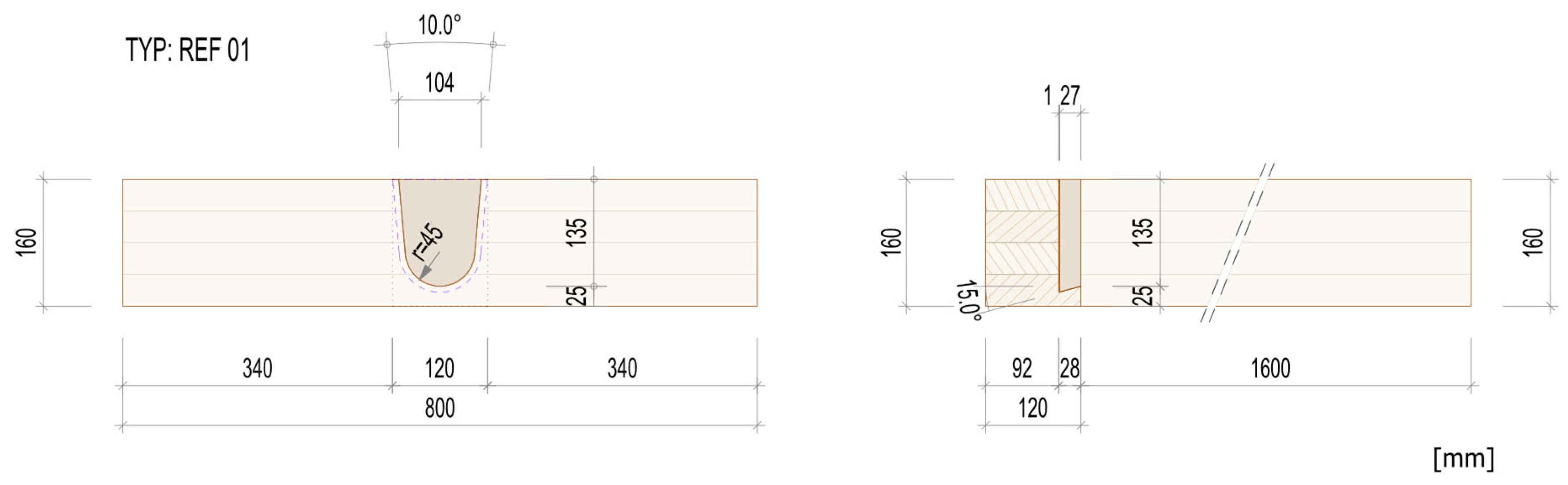
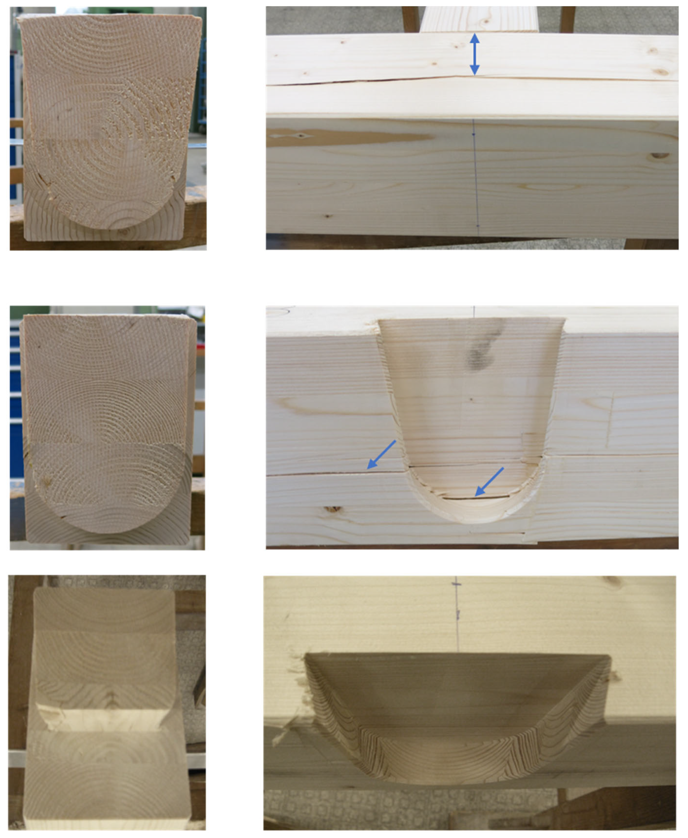
When evaluating the GLT girder combinations series REF 01, ZGR 01, FLA 01, it can be seen that the failure modes of the reference form REF 01 as well as the basic tenon form ZGR 01 are almost identical. In both cases, a transverse tension failure of the main girder occurs, see
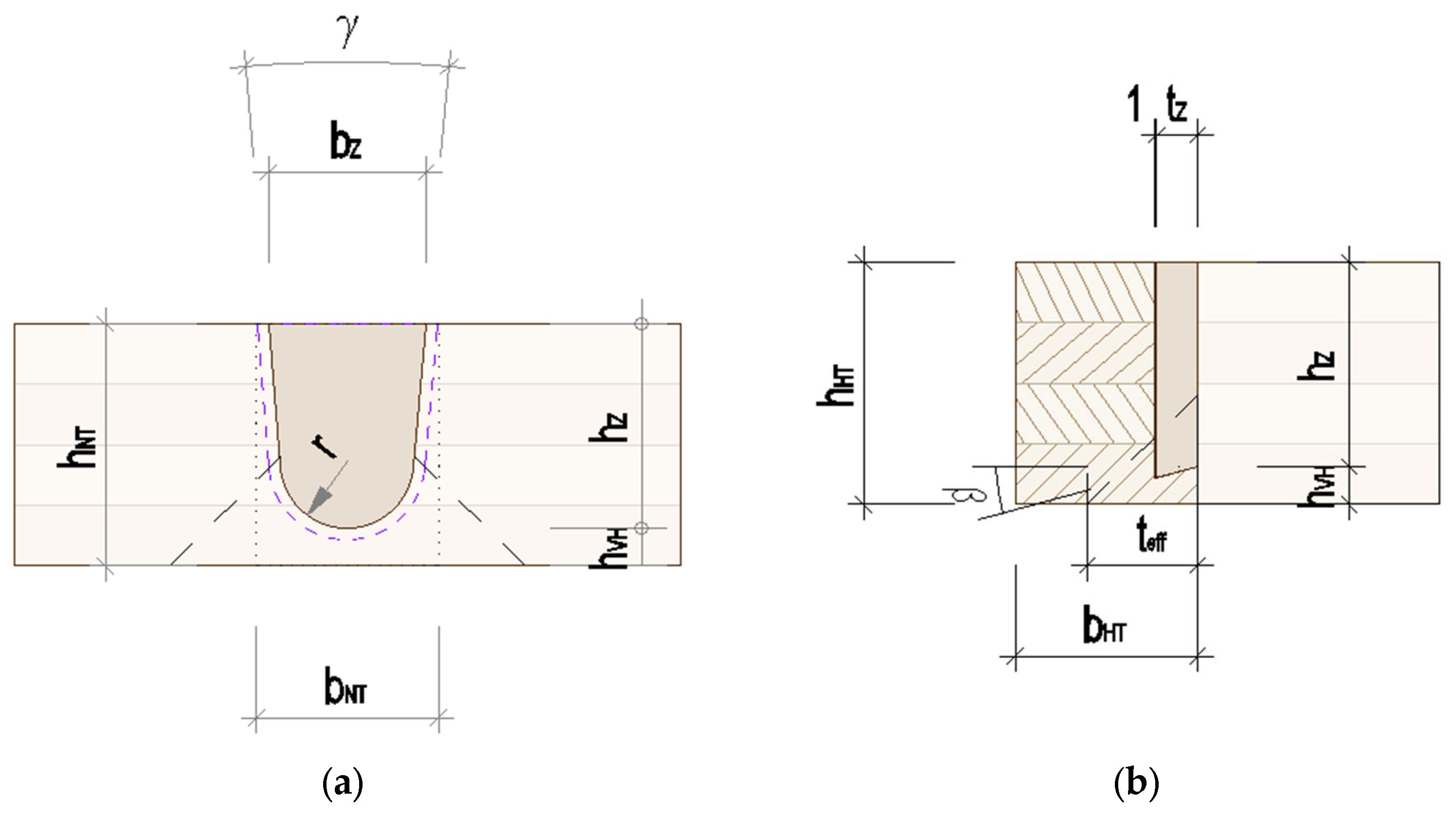
Figure 10. The effective depth
teff in the test runs is approximately 0.75∙
bHT. This value is significantly lower than the uniform calculation value of
teff = 100 mm for transverse connection failure (mode 1) for single-sided dovetail connections specified in Z-9.1-649 [
1]. Since
teff is a significant factor in the calculation formula for the load-bearing capacity of the transverse connection, it can be determined that the calculated characteristic load-bearing capacity for mode 1 according to [
1] is not achieved in the test runs of series ZGR 01, which takes the shrinkage of the flanks into account, if the pre-timber height
hVH = 0.15
hHT is given. The REF 01 series reaches the calculated value during the test, but only due to the existing flank load components. These are not taken into account in the calculation formula of the Z-9.1-649 [
1] approval. Lower pre-timber heights
hVH = 0.05
hHT (REF 03 series under 3.1.2) lead to lower connection depths
teff and thus to larger deviations of the bearing capacity of the tapping base from the calculated value for mode 1 according to [
1].
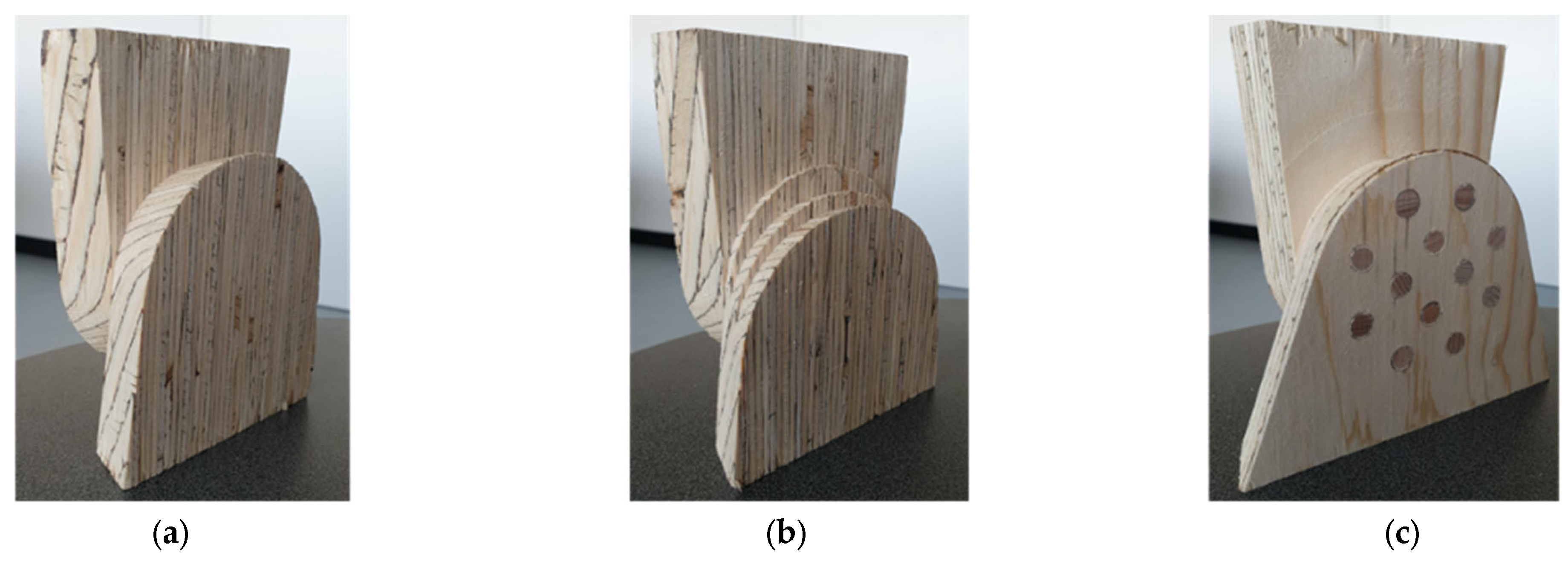
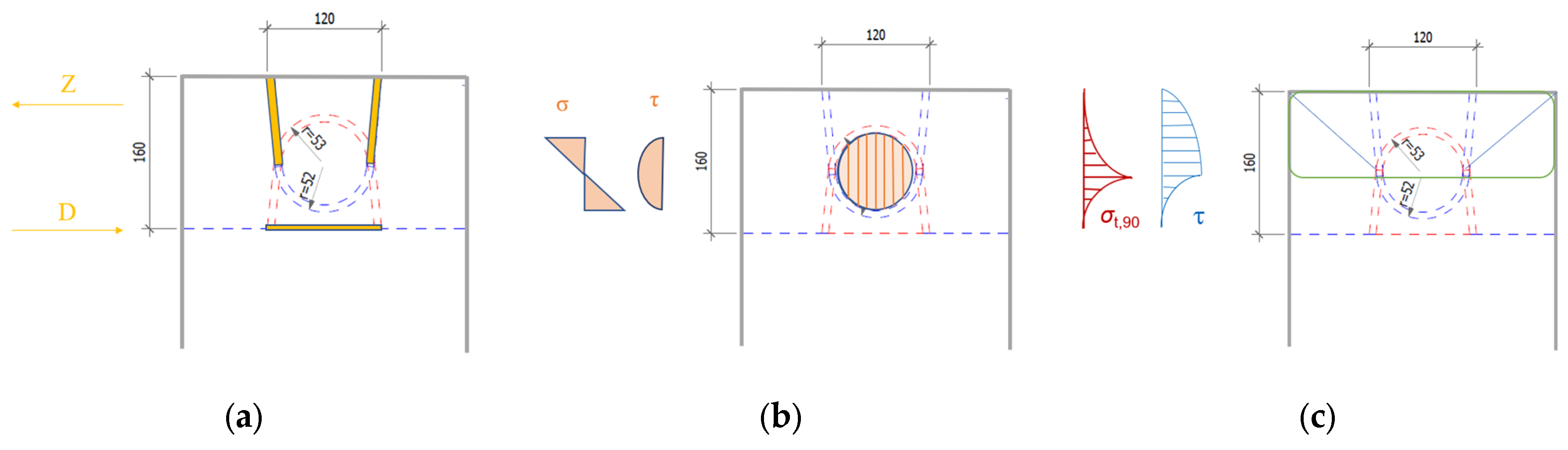
To determine the separately investigated load-bearing components of the tapping base and the flanks, their stiffness is determined by means of series ZGR 01 and FLA 01. These are then related to the total stiffness of the reference form series REF 01. In the course of the investigation of REF 01, it is found that the stiff tenon base is initially the main force transmission path of the joint. With increasing changes in the stiffness ratios, due to incipient damage in the tenon base, rearrangement processes occur towards the flanks. The residual load-bearing capacity of the wood connection, which is approximately 75% of the ultimate load, is ensured by the flanks. Since the force transmission via the flanks has little stiffness, noticeable deformations occur after failure of the bearing capacity of the tenon base. This effect is clearly visible in series FLA 01, since the trunnion does not rest on the bottom of the tenon hole. That means, the bottom of the main beam remains undamaged, see
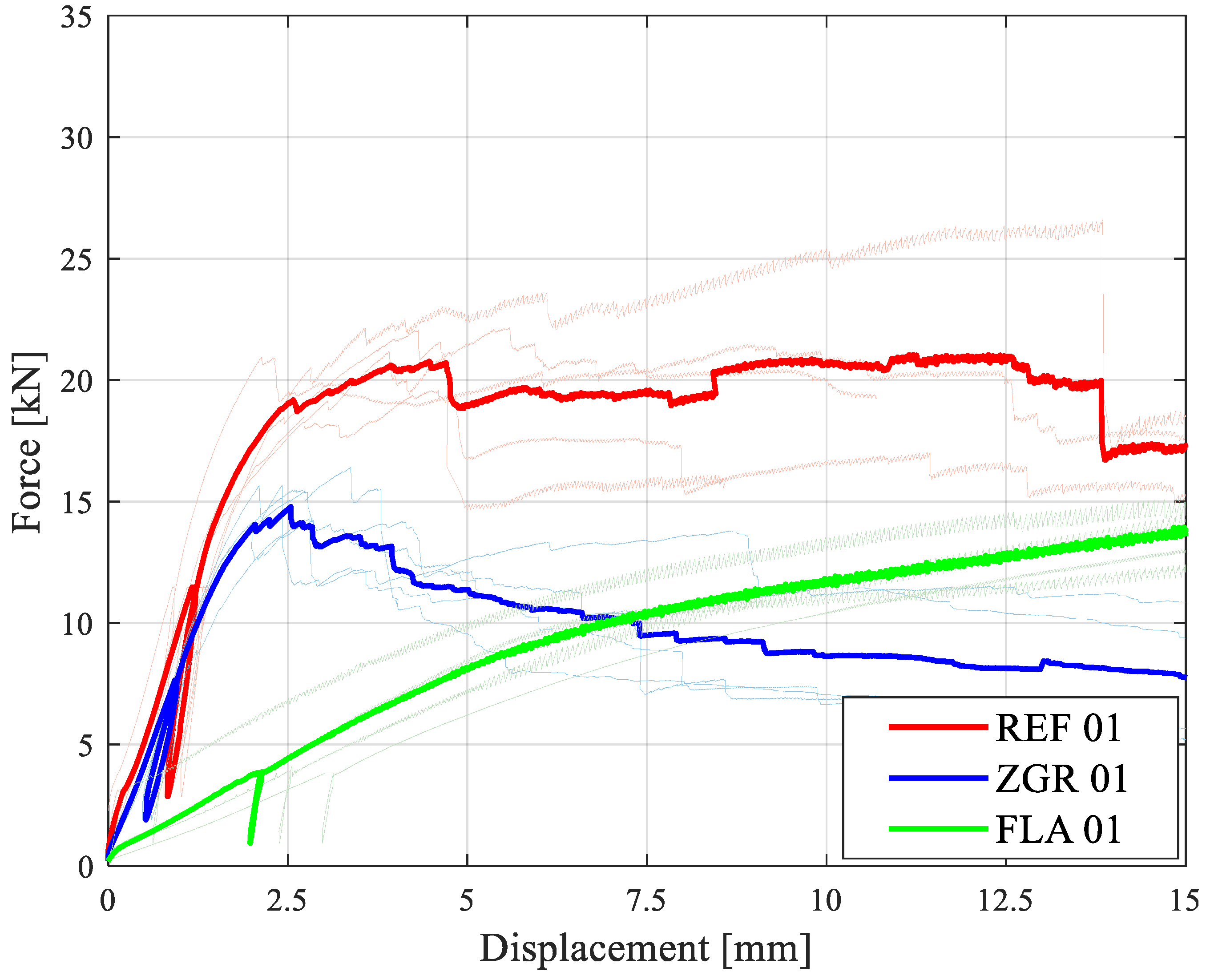
Figure 10, and the stiffness of the connection is represented only by that of the flanks. For series FLA 01 the stiffness is therefore very low. All load-deformation mean value curves for 120 mm × 160 mm beam combinations are shown in
Figure 11. Their loads and stiffnesses are listed in
Table 2.
The investigations of the stiffness on GLT girder combinations with cross sections of 120 × 160 mm show that the participation of the load transfer over the flanks, which contributes to series REF 01, amounts to 15% (see
Figure 12). As already mentioned, in common calculation models the flank load transfer part is not considered. However, at low pre-timber heights, redistribution processes from the bottom of the journal to the flanks already occur at small load steps. The flanks guarantee a residual load-bearing capacity of almost 75%, which is important for the robustness of the connection and the structure as a whole. The characteristic load of the reference geometry REF 01 achieved in the test, corresponds exactly to the calculated value according to [
1]. However, the value of the pure tenon base form ZGR 01 is lower. In the case of beam combinations of the same height, the calculated value according to [
1] is only achieved in the present test runs if the flank load-bearing component is taken into account.
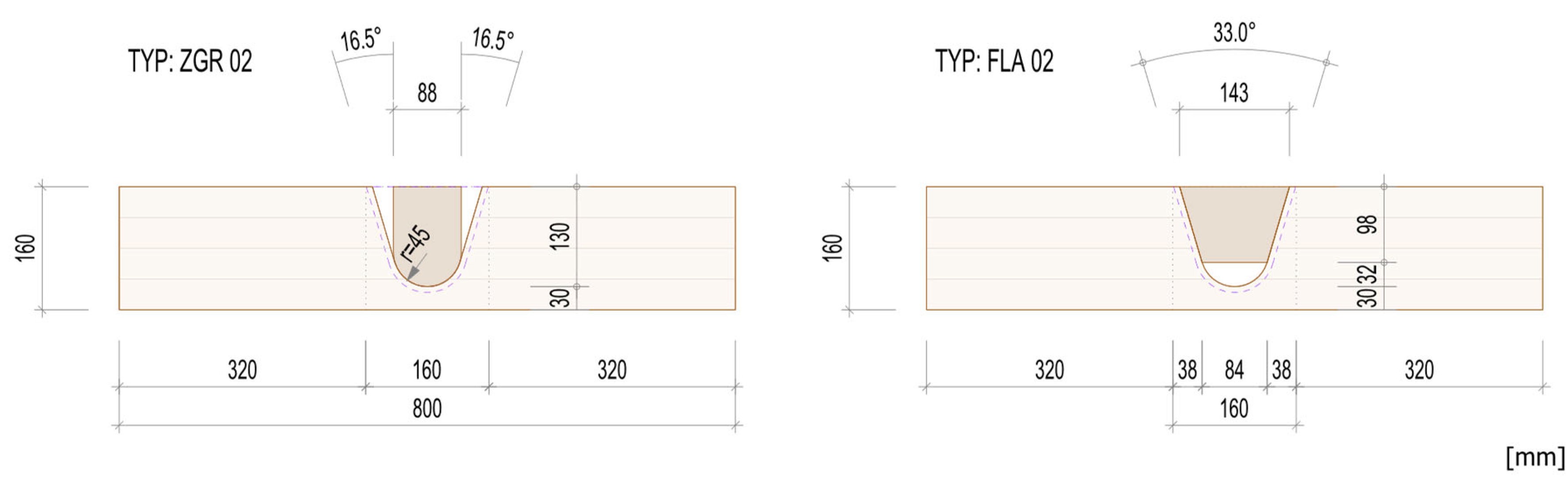
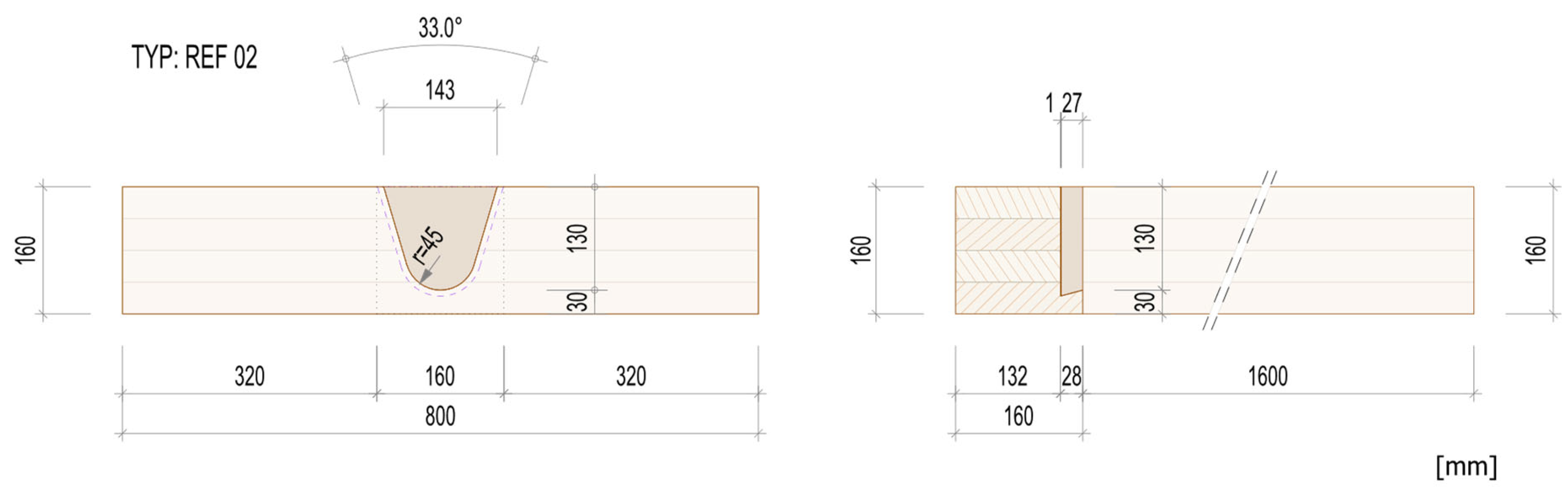
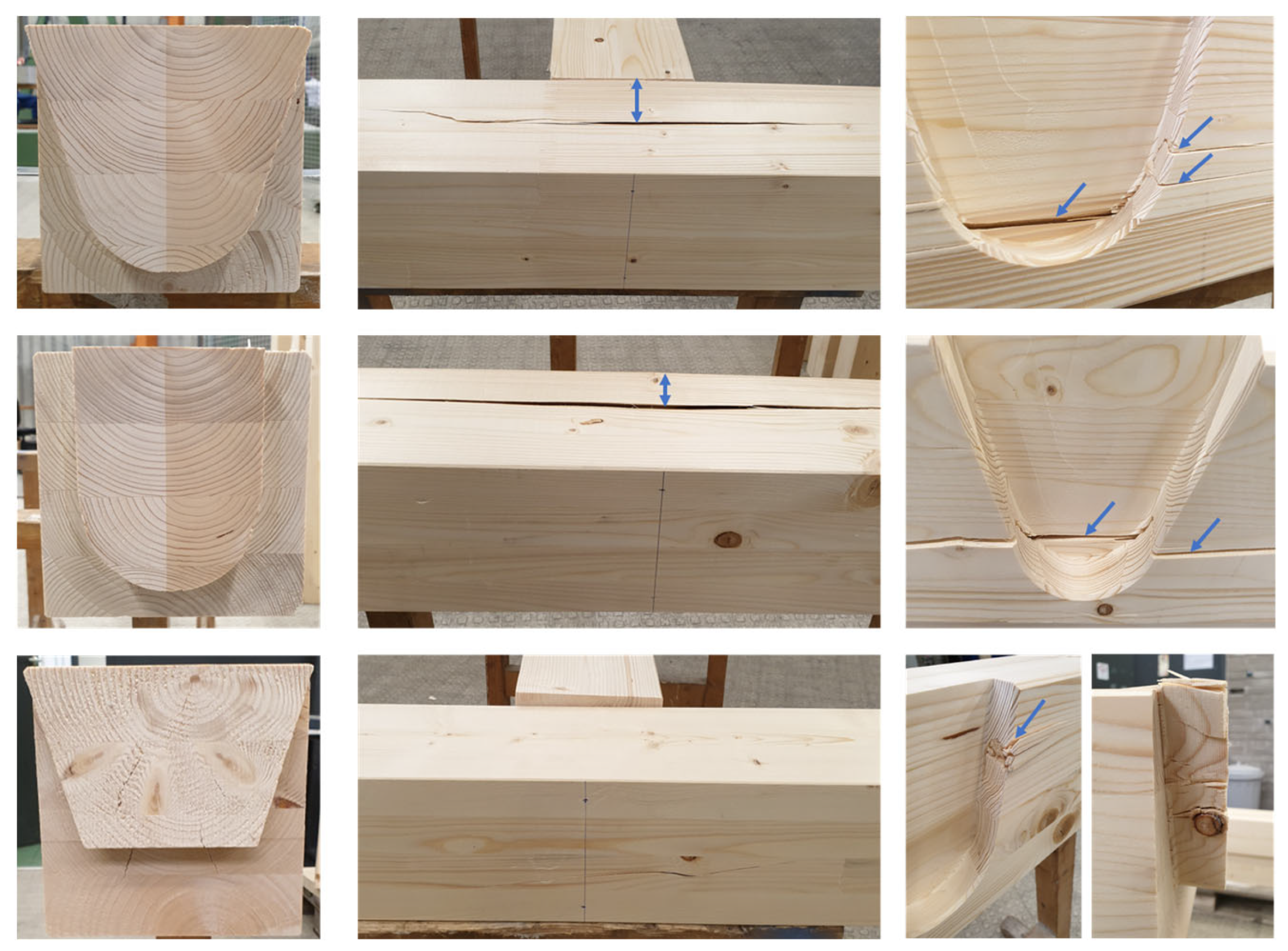
In order to demonstrate the optimization potential for shapes with a larger notch taper angle
γ, GLT beam combinations series REF 02, ZGR 02, FLA 02 were investigated in the same way as in the previous series. The failure mode of the reference geometry REF 02 now differs from the corresponding basic tenon shape ZGR 02 by a multi-step force application due to the load-bearing components of the flanks. This leads to a higher total resultant force transmission, which is shown by a greater effective depth
teff of the reference shape compared to the basic tenon shape. The FLA 02 series flank form is again tested without the tenon base. The load achieved with the FLA 02 series is higher than with the FLA 01 due to the wider flank angle. This is also visible in the damage patterns of the main beam (see
Figure 13).
The basic tenon form, ZGR 02, shows exactly the same values as the corresponding basic tenon form, ZGR 01. Its calculated load-bearing capacity can also be estimated on the safe side by using the calculation formula for mode 1 in [
1]. The significant increase in the load-carrying capacity of the reference form REF 02 compared to REF 01, therefore results exclusively from the higher flank load-bearing component because of the wider notch taper angle. The ductile behavior of the connection and the robustness of the structure as a whole can also be guaranteed by widening the notch taper angle
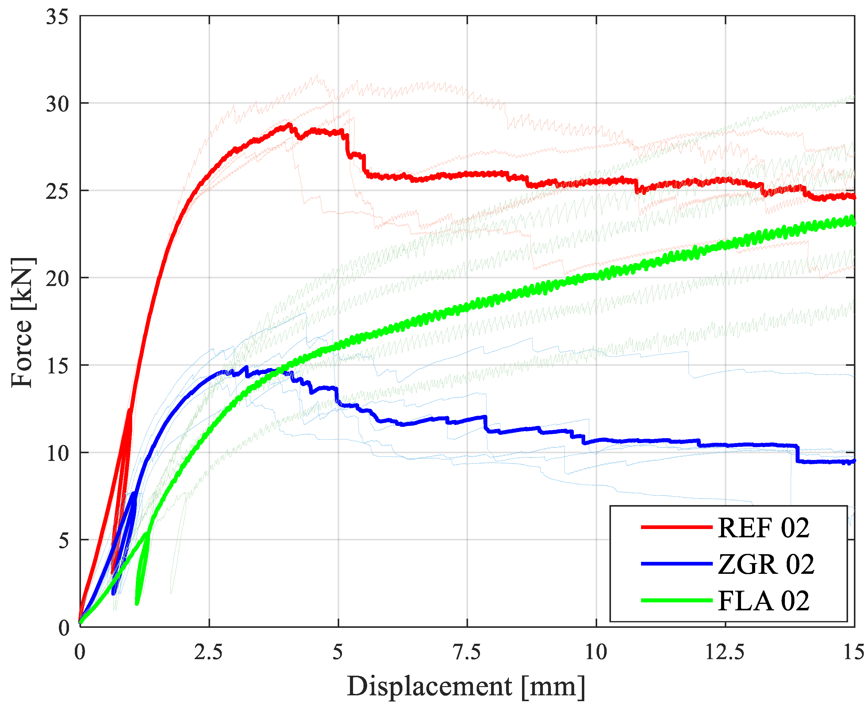
γ. The increase in load-bearing capacity before failure and the residual load-bearing capacity at failure of the connection depend exclusively on the flank load-bearing component and thus on the inclination of the flanks. The potential of this load increase for the REF 02 series is 66%, compared to the ultimate load of the basic tenon form ZGR 02, which is relevant for the design. After failure of the tenon base, approximately 90% of the ultimate load at an opening angle of 33° is available as residual load-bearing capacity through the flanks in the case of large deformations. Taking the flank load-bearing components into account in the calculation formulas would lead to a significant increase in the ultimate load potential of the timber connection at large opening angles. Due to the early onset of redistribution effects with beam combinations of the same height, these could also be included in the ultimate load calculation—assuming appropriate milling accuracy and limitation to NKL 1. The flank load-bearing components certainly ensure the robustness of the structure as a result of their considerable residual load-bearing capacity. All load-deformation mean value curves for 160 mm × 160 mm beam combinations are shown in
Figure 14. Their loads and stiffnesses are listed in
Table 3.
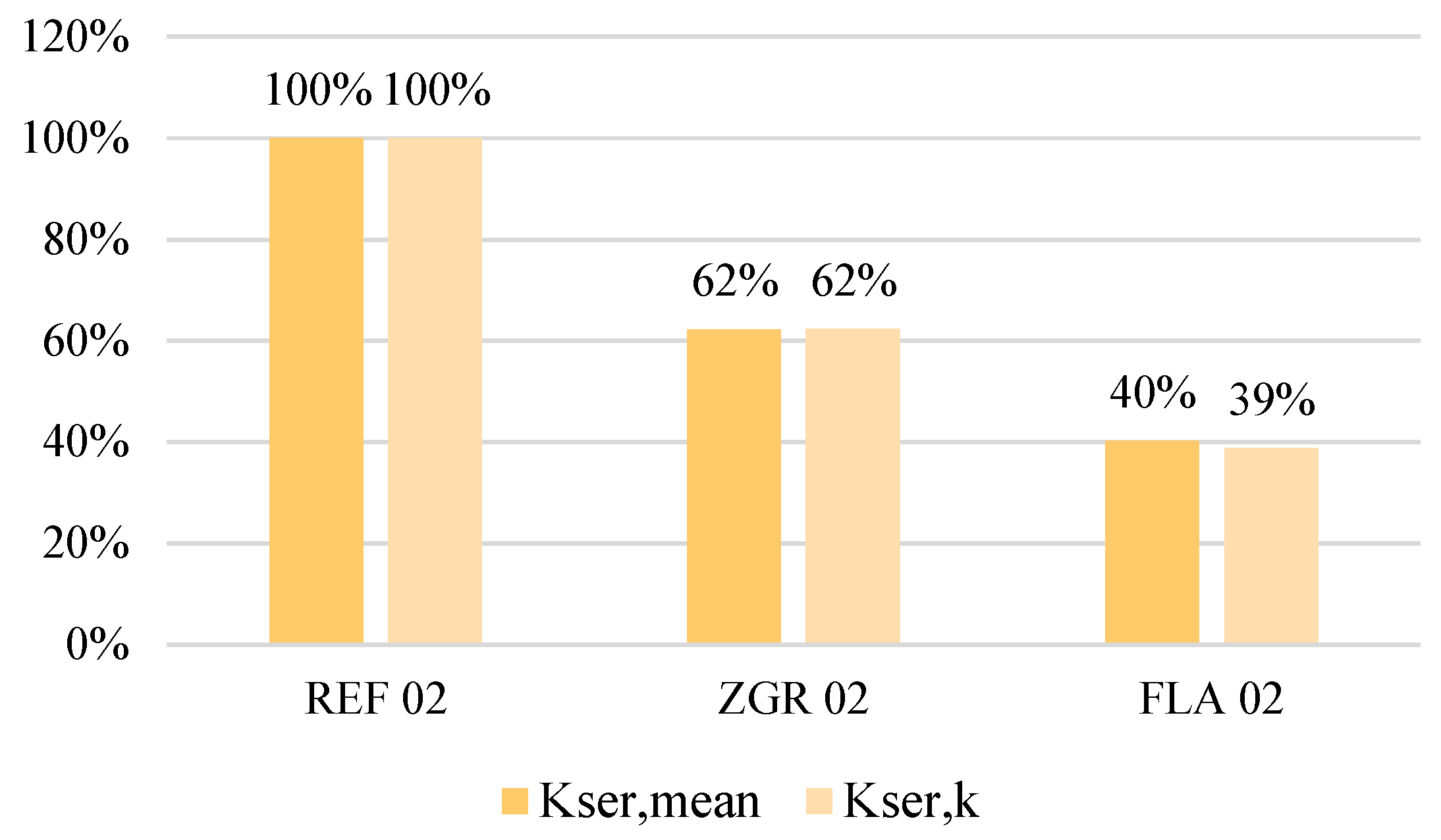
The contribution of the flanks to the force transmission can be illustrated by comparing the stiffness of the results on GLT girder combinations with cross sections of 160 × 160 mm of the REF 02, ZGR 02 and FLA 02 series. This results in a load participation of the flanks of 40%, which contributes to the reference form REF 02 (see
Figure 15).
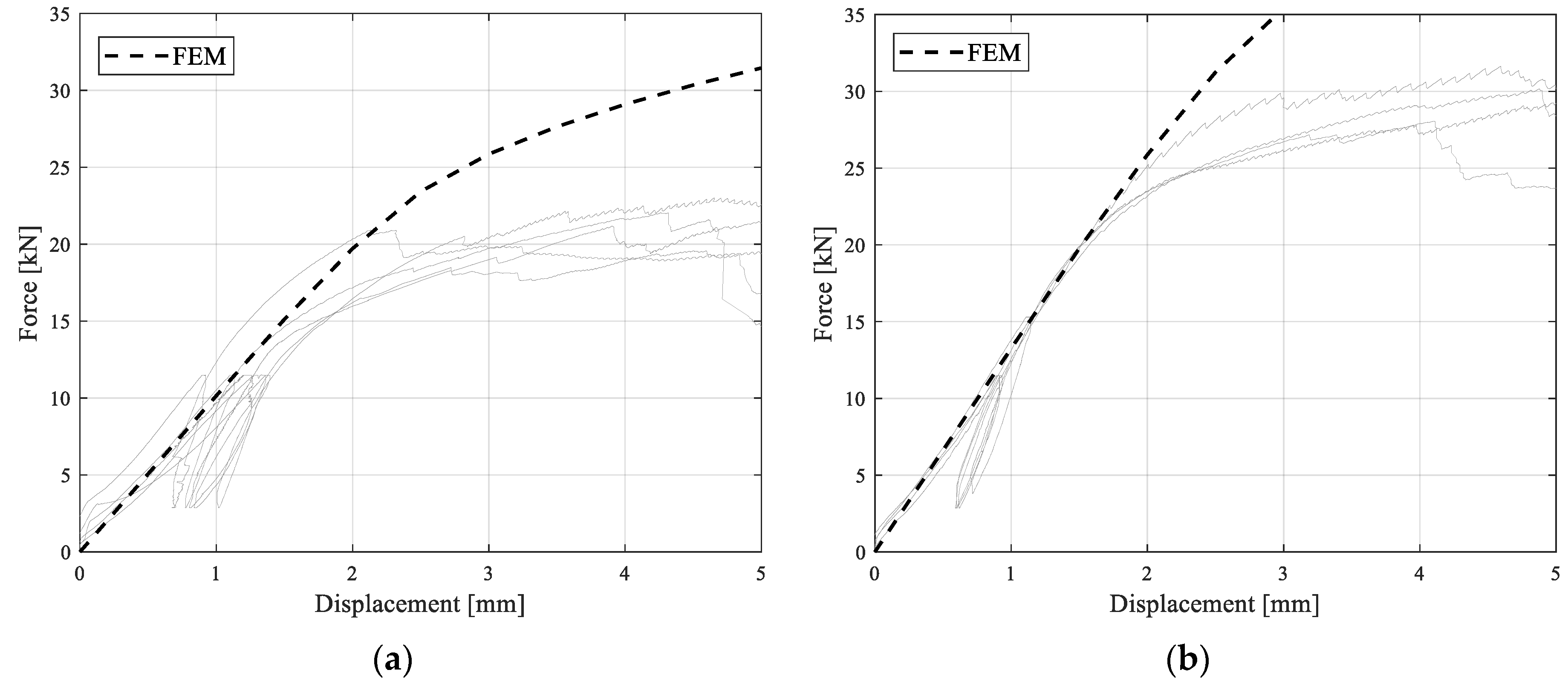
Stiffness values for solid spruce wood C24 according to EN 338 [
17] and yield stresses according to Sandhaas and van de Kuilen [
18] are applied for the bilinear material model with Hill yield criterion and isotropic hardening in the course of the simulations (
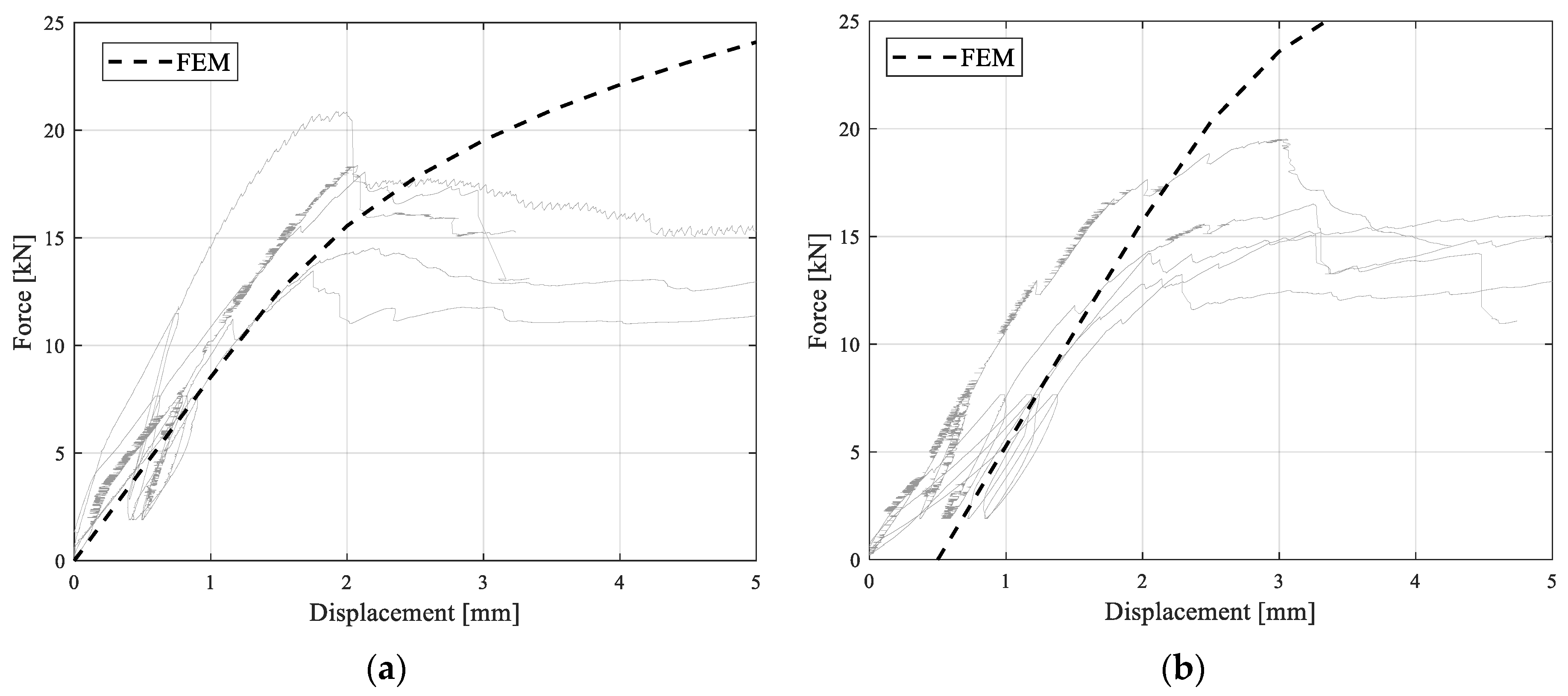
Table 1). All results of the test runs of the reference geometries REF 01 and REF 02 can thus be validated in numbers (see
Figure 16).
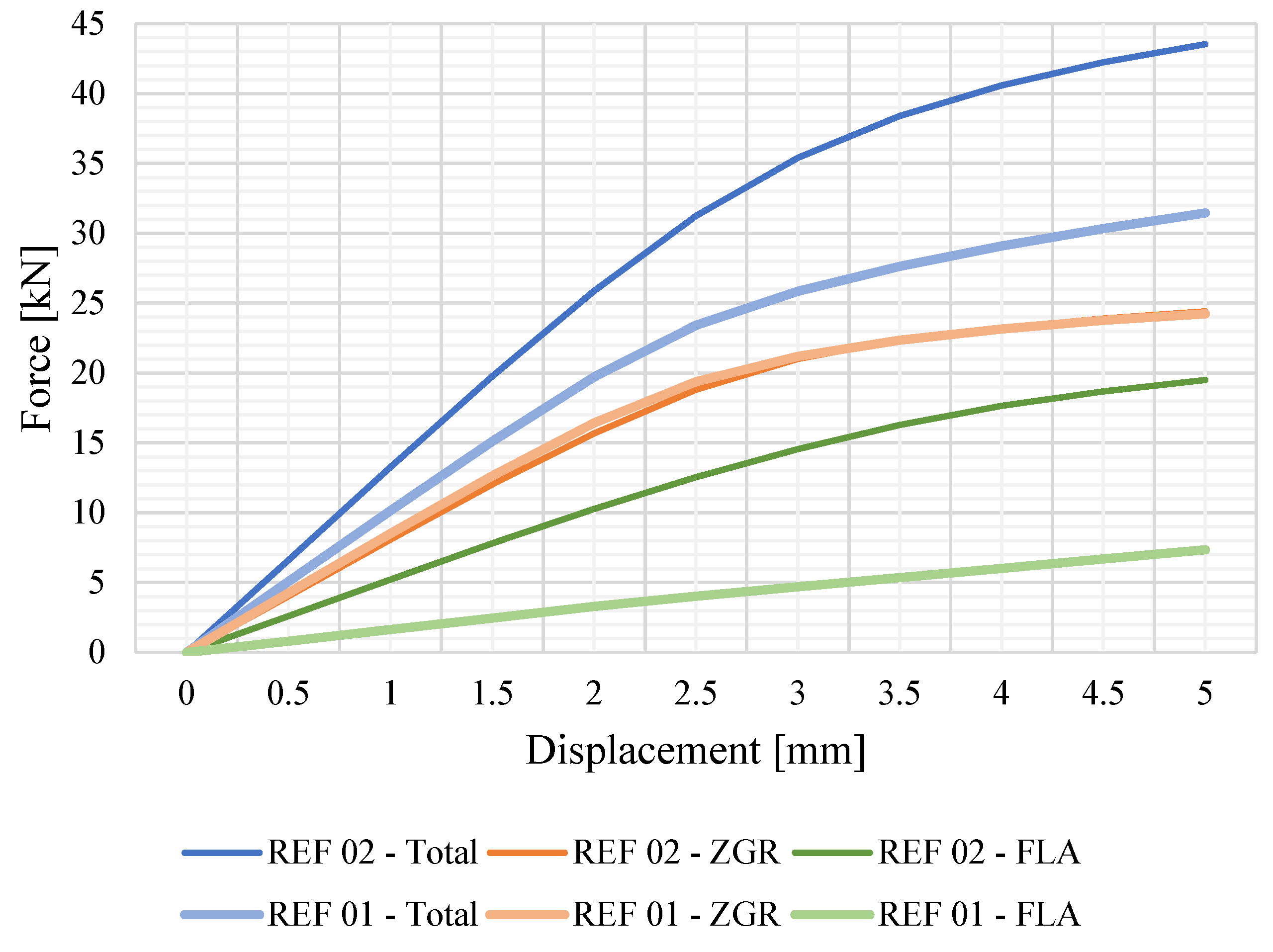
The flank load components can be confirmed in FE simulations of the two reference geometries REF 01 and REF 02 (
Table 4). The same applies to the fact that both tenon bases show identical load-bearing behavior in the FE simulations (cf. series ZGR 01 and ZGR 02). This confirms that improved load bearing and stiffness properties in the tests result exclusively from increased properties of the flanks (see
Figure 17).
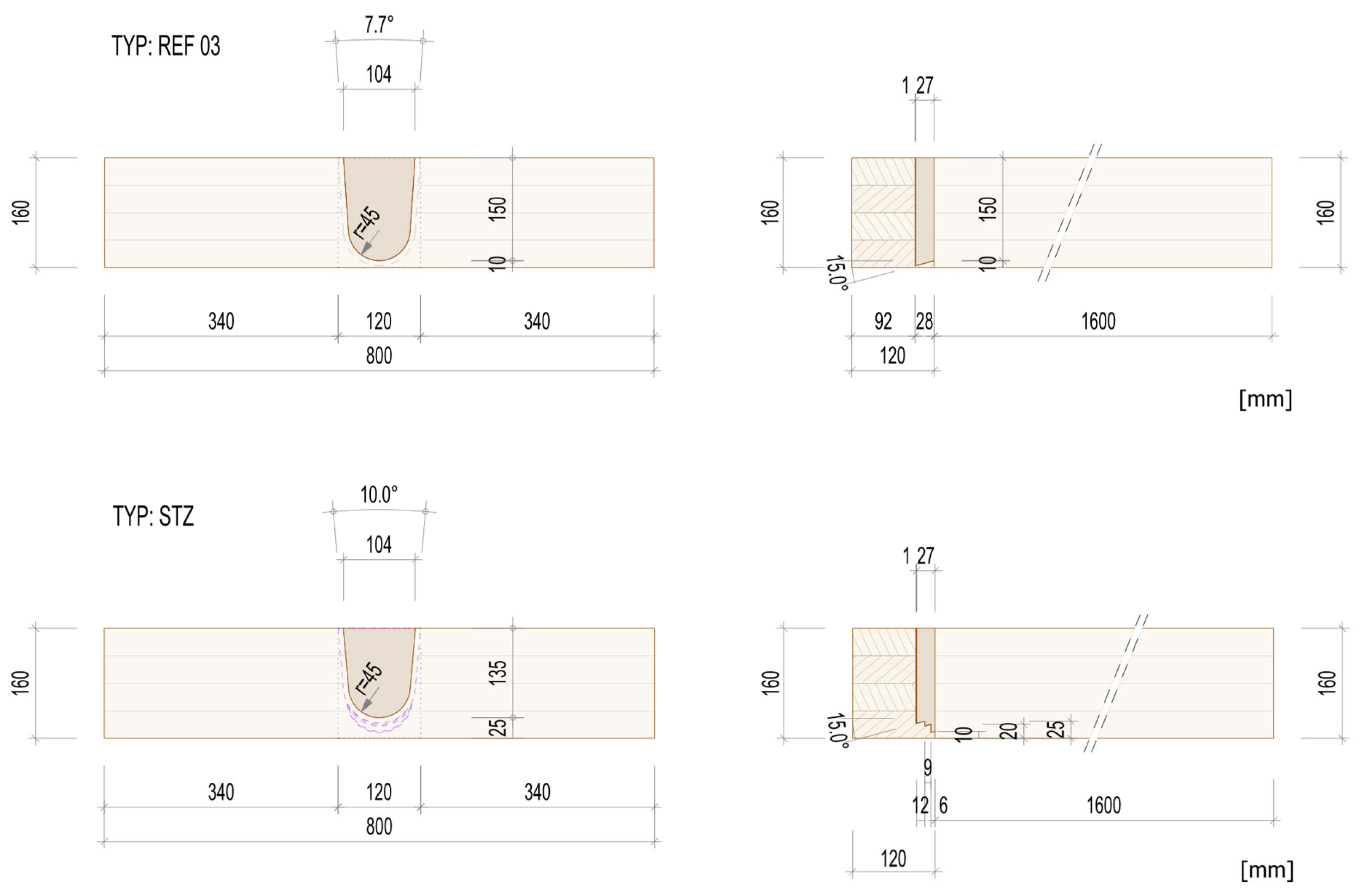
3.1.2. Bar-Shaped Investigations—Stepped Tenon Base
Girder combinations with low pre-timber heights hVH at the main girder fail by exceeding the transverse tension strength. The main reason is that there is too little transverse tension volume available due to insufficient connection depth teff below the fillet of the main girder. Moreover, the combination of a low transverse tension strength of the wood and load introductions with a low pre-timber height, lead to premature transverse tension failure resulting from defects in the wood.
The total dimensions of the pre-timber of the main beam is composed of:
As already mentioned, the unfavorable case of load distribution occurs with beam combinations of the same height, as frequently applied in practice. Z-9.1-649 [
1] does not limit this dimension parameter and allows
teff = 100 mm in any case in the transverse tension check for mode 1 failure (transverse connection—failure of the main girder side).
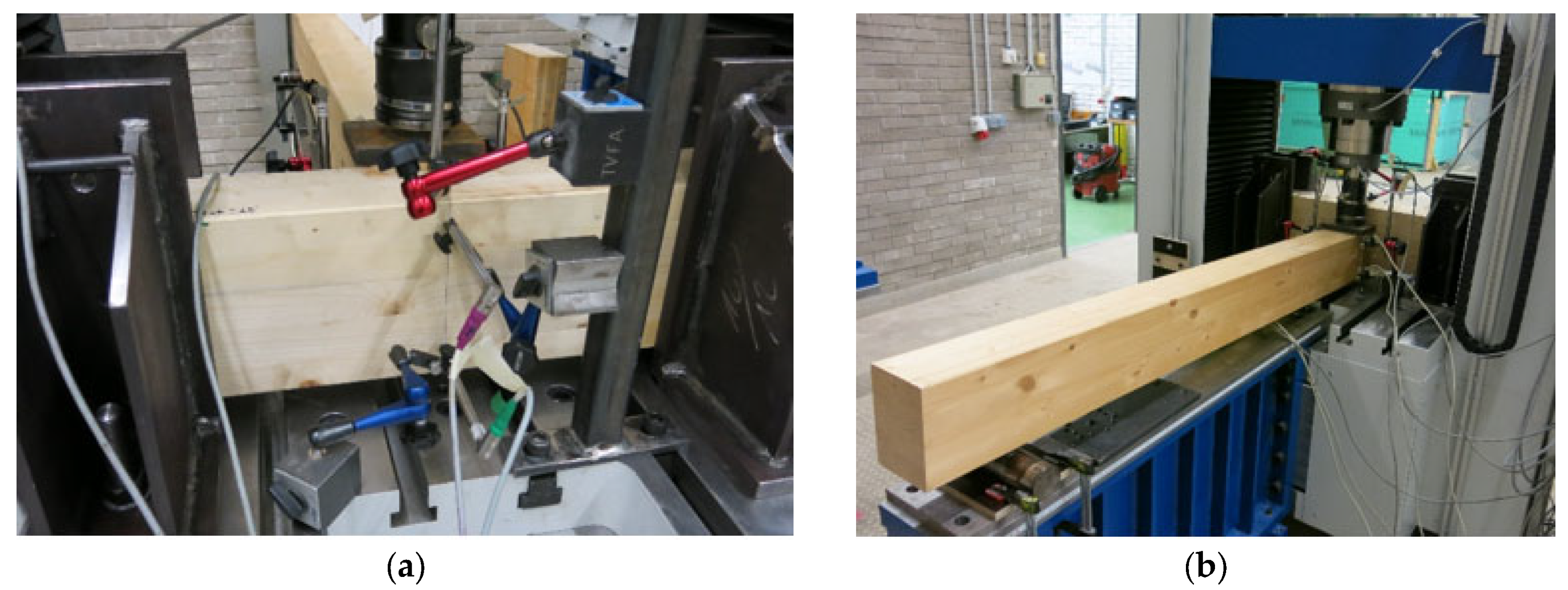
In order to investigate the bearing behavior in such a case, a test series of 120 × 160 mm GLT-girder combinations with minimum pre-timber heights and permissible geometry parameters was developed according to [
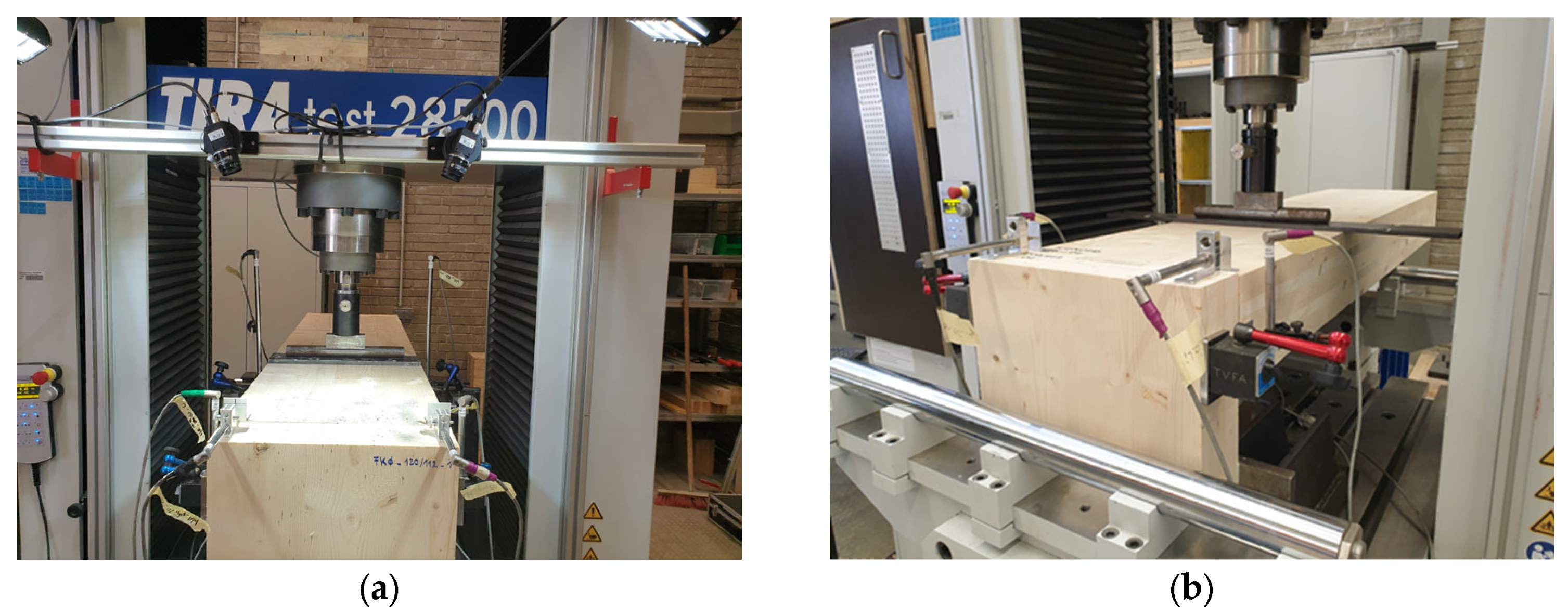
1]. The REF 03 series was thus tested in five tests and on the same test setup as in the previous investigations with respect to mode 1 failure according to [
1]. Furthermore, a series is developed following the measure of a “double dovetail tenon” set by Tannert in [
3]. Step-shaping the depth of the tenon forms a three-row shape of the stepped tenon base, starting from the fillet of the tenon. The individual levels of the steps are optimized in terms of their widths and heights so that the uppermost step has the maximum width and can thus take the most load. The aim here is to distribute the load application over several levels. This results in a more favorable distribution of the transverse tension stresses in the area of the fillet of the mortise of the load-bearing side and a delayed failure of the main girder. By introducing part of the forces at the higher level (uppermost step), a greater connection depth
teff is achieved and thus a greater transverse tension volume is attained. As a result, even imperfections in the wood have hardly any influence on the load transfer.
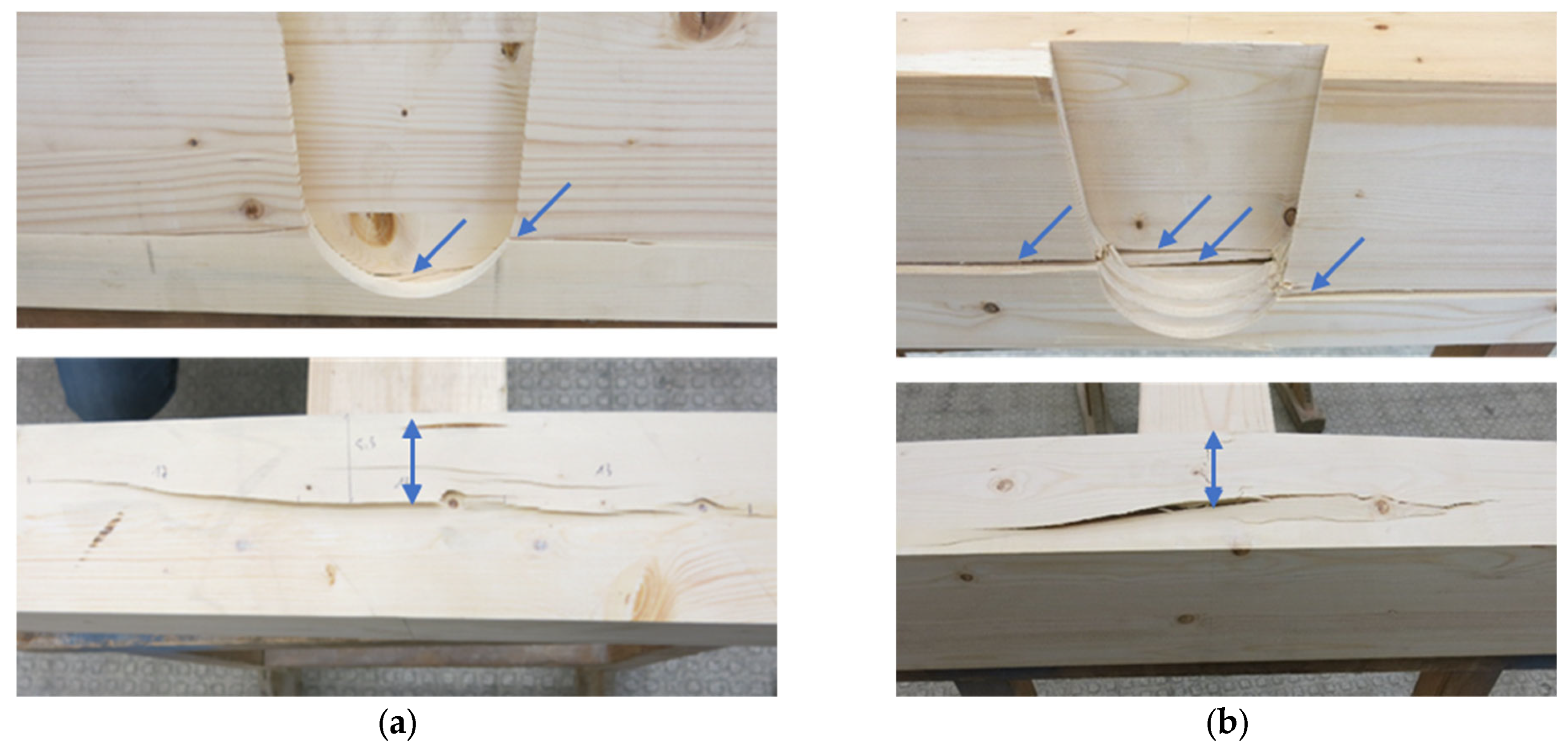
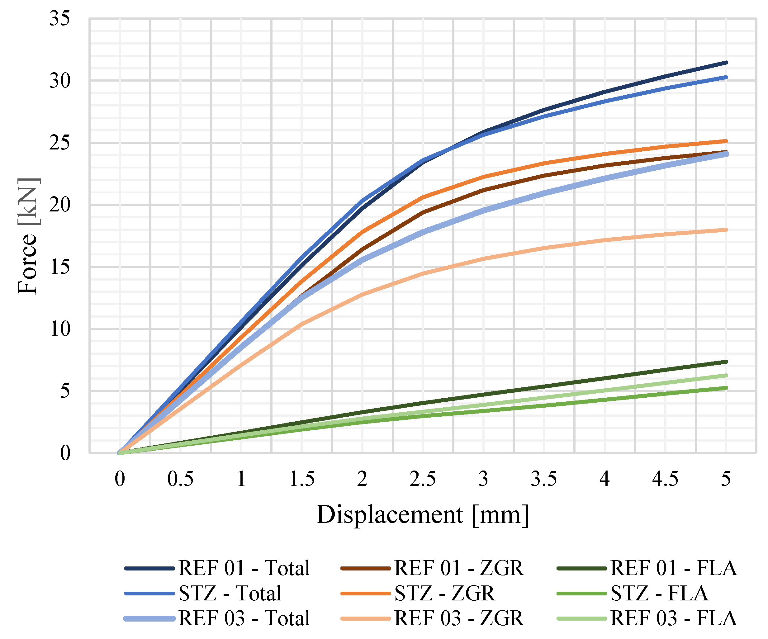
Due to the stepping of the tenon base, the connection depth
teff of series STZ increases by approximately 50% (see
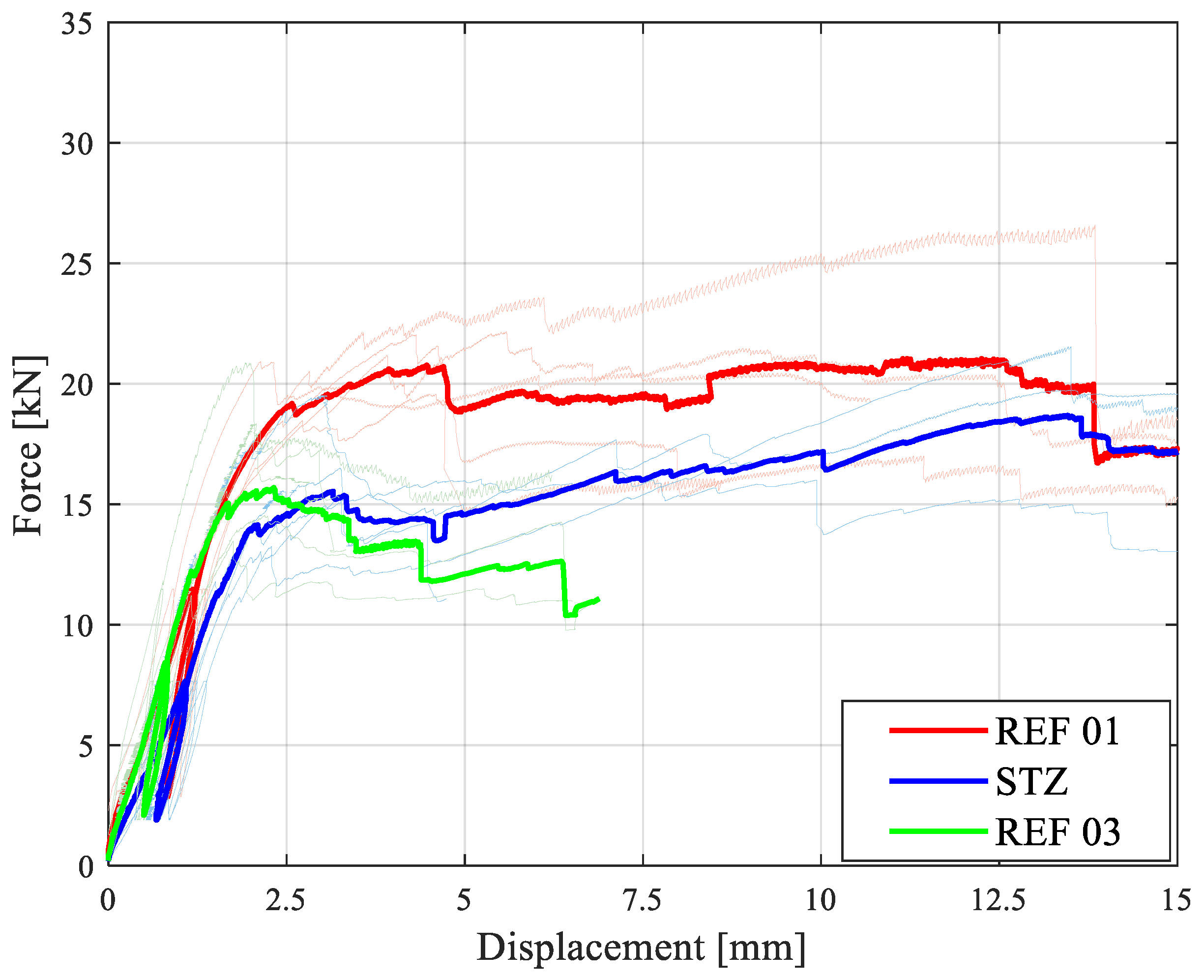
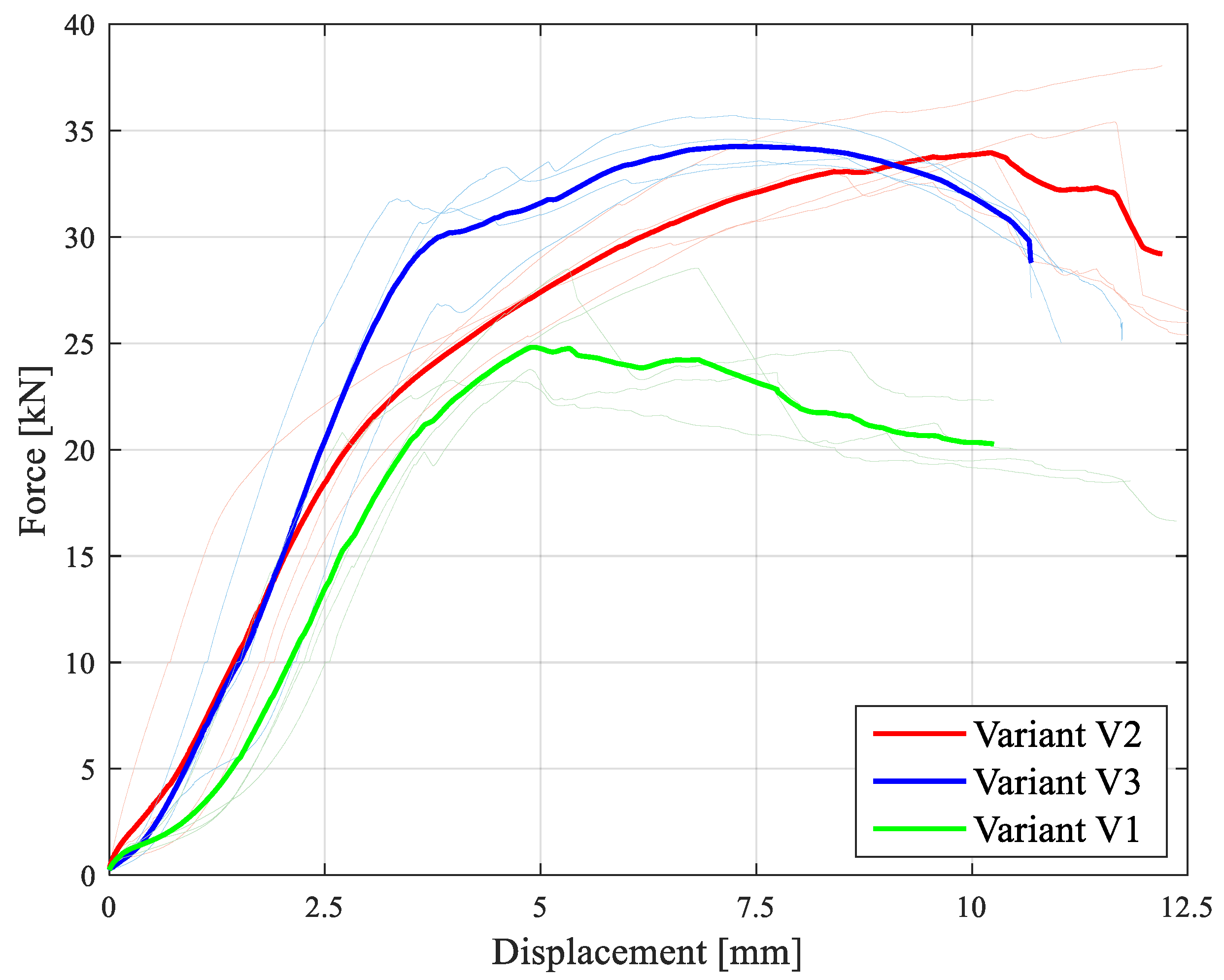
Figure 18). The loads of the mean value curve of series STZ can almost reach those of the reference geometry REF 01 at 15 mm deformation (see
Figure 19). Therefore, REF 01 is taken into account in all comparisons.
The high spread of the ultimate loads in the REF 03 series with minimum pre-timber height is striking, which is due to the effects of local defects and thus premature failure. The tests of this reference geometry spread with respect to the ultimate loads
Fv,k at a covariance COV of 18% (see
Table 5). The minimum initiation height from the beginning of the fillet of the mortise to the lower edge of the girder is only capable of ensuring a connection depth
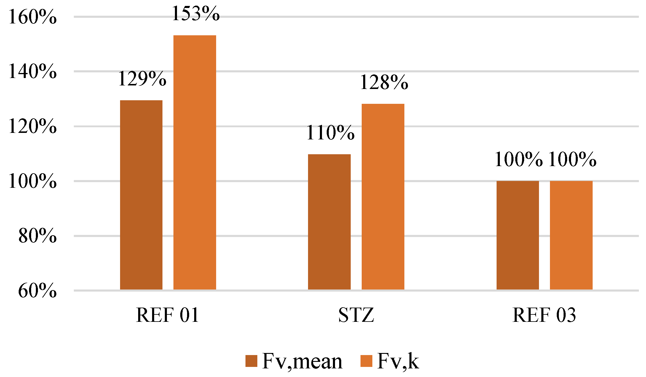
teff of 50 mm. The widely spreading values are due to local defects, which lead to different transverse tension crack propagation. This results in premature failure below the tenon base of the load-bearing main girder without redistribution possibilities. In contrast, the stepped tenon base geometry of the STZ series exhibits a high dispersion in terms of its stiffness. This is due to the form closure on several levels and the associated tolerances, i.e., until the closing of the multi-stage overall system. However, the load transfer to the multiple levels results in a significant increase in the ultimate load, which has a positive effect on the characteristic calculation value
Fv,k in particular (see
Figure 20). The initial stiffness values
Kser spread with a covariance (COV) of up to 32% (see
Table 5). However, if deformations of up to 15 mm are allowed, the connection force-locks at all step levels. The mean load curve of the STZ series thus approaches that of the reference form REF 01 at 15 mm deformation.
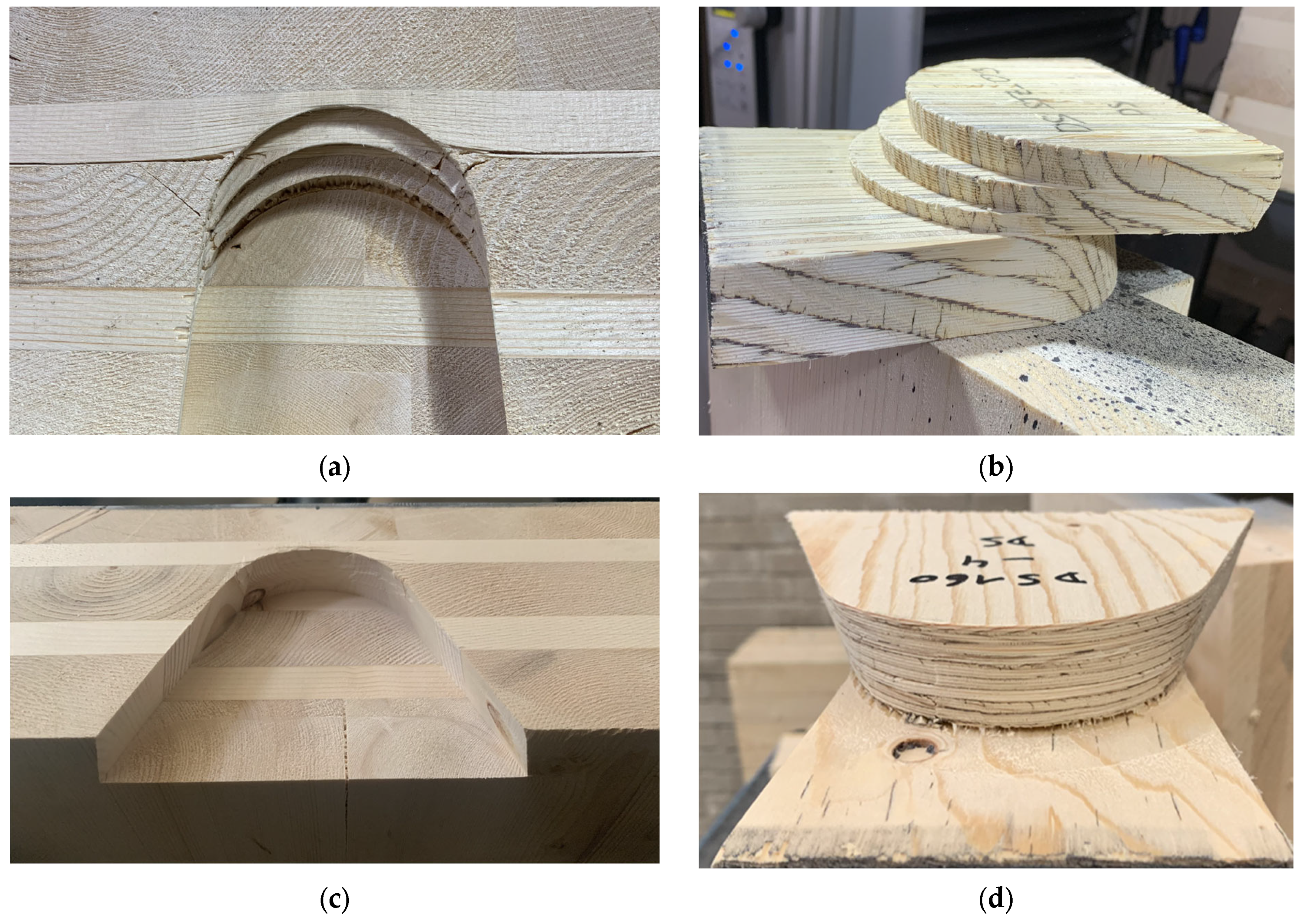
By stepping the tenon base, a height distribution of the load application can be achieved, which is also reflected in the fracture patterns. Failure is thus not determined by a defect in the transverse tension volume. Ultimately, all test specimens reach a similar ultimate load level after deforming to a higher or lesser degree. The individual levels of the stepped tenon base communicate with each other, so that in the event of an individual level yielding, the load can be redistributed to other, intact levels.
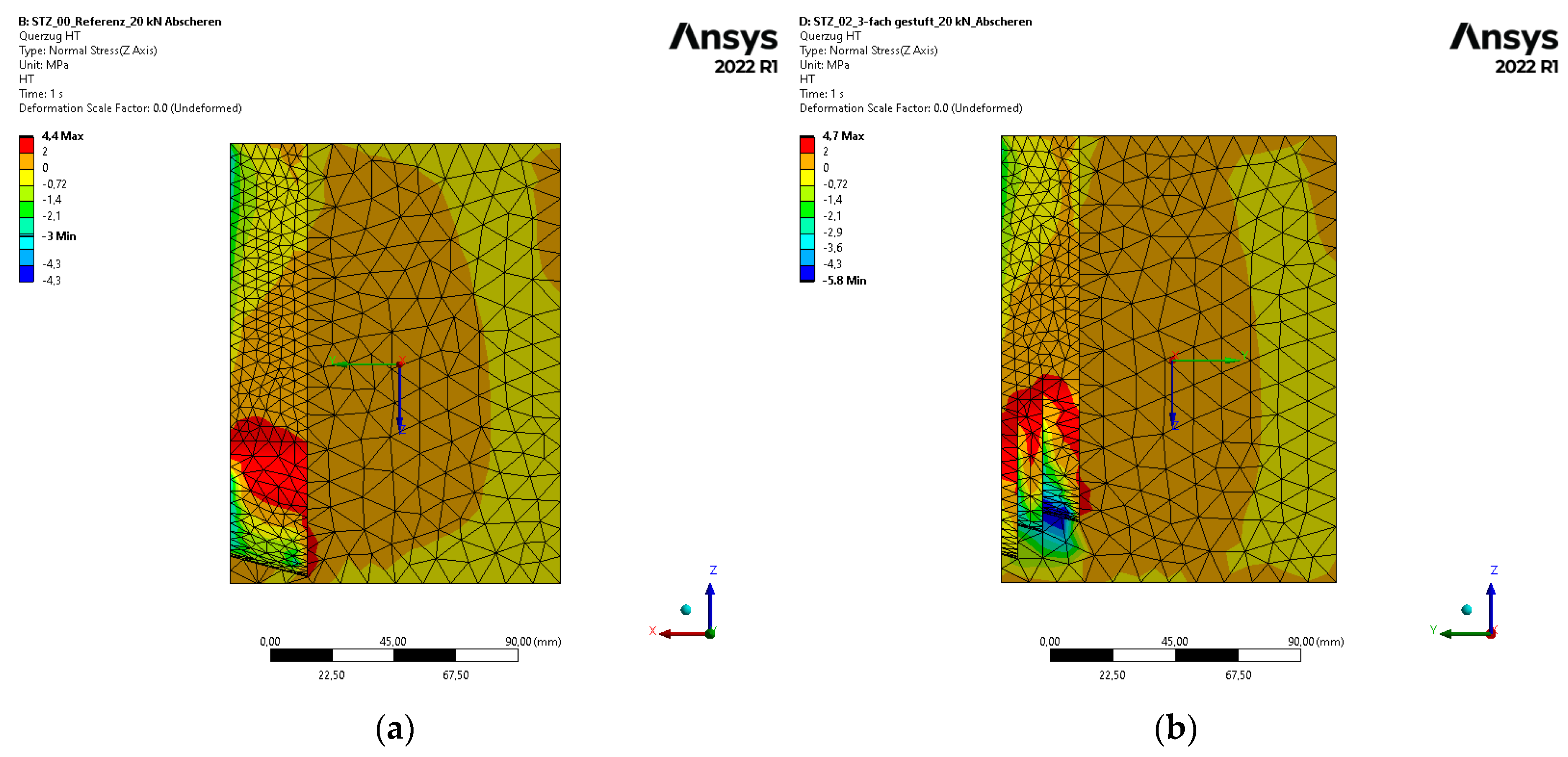
In the reference form REF 03, the entire force is applied via the single “step” located far below, with a low connection depth teff. As a result, only a small transverse tension volume of the main girder is activated in the transverse connection. If the load introduction is distributed over several levels according to the geometry of the STZ series, an overall higher force introduction is achieved. In this way, approximately 75% of the width of the 120 × 160 mm main beam bHT can be activated as the resisting connection depth teff. The stepped tenon base is designed so that the step with the lowest connection depth also introduces the lowest load component. The two higher steps introduce higher load components with greater effective connection depths. This means that the widest step at the top transfers more than half of the resultant force to the load-bearing main beam.
The positive effect of the stepping can also be seen in the course of numerical simulations (see
Figure 21).
Stiffness values for solid spruce wood C24 according to EN 338 [
17] and yield stresses according to Sandhaas and van de Kuilen [
18] are applied for the bilinear material model with Hill yield criterion and isotropic hardening in the course of the simulations (
Table 1). All results of the test runs of the reference geometry REF 03, as well as the stepped tenon base geometry STZ, can thus be validated in numbers (see
Figure 22).
Due to the delayed closure of the entire system in the tests with the stepped tenon base shape STZ, the FE curve had to be shifted by 0.5 mm.
The mean value curves of the test results of the REF 01 and STZ series show equally high ultimate loads (see
Figure 19), although those of the stepped tenon base form are only reached at deformations of 15 mm. In the FE model, these series show the same initial stiffnesses
Kser (see
Figure 23). The initial stiffness
Kser is overestimated in the FE model for the STZ series, since the problem of closing the individual steps resulting from a lack of fitting accuracy is not covered by the model.
Reference form REF 03 shows the lowest initial stiffness,
Kser, in the FE model (see
Figure 23). The ultimate loads in the tests of the REF 03 series, shown in
Figure 19, are all reached within deformations of 5 mm. Furthermore tests of REF 03 show a higher initial stiffness,
Kser,
mean, as in the FE model because of a positive “outlier” in the tests (see
Table 6).
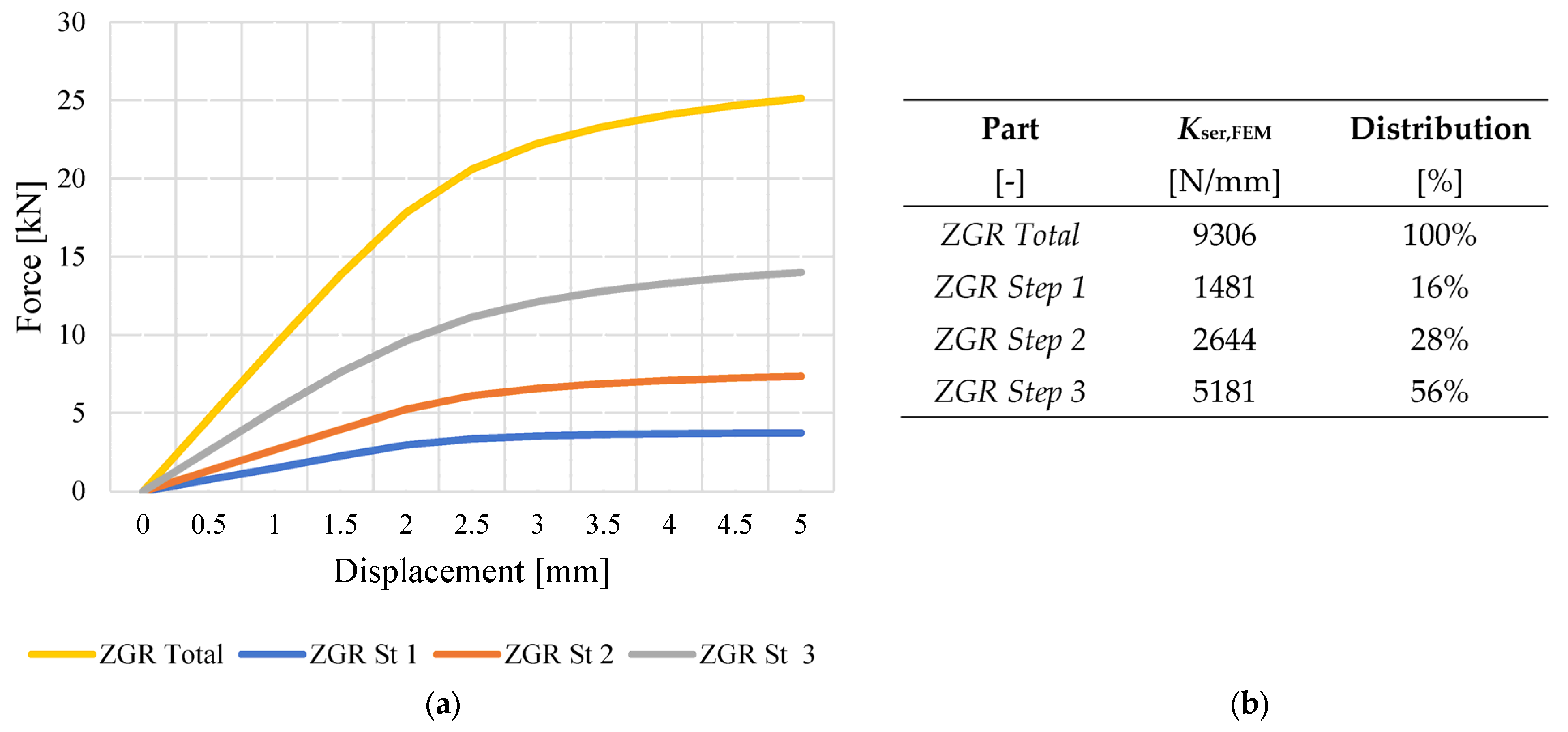
The individual steps of the tenon base attract different load proportions (see
Figure 24). The widest, step 3 at the top, absorbs more than half of the load share of the entire tenon base. In general, the FE model for the STZ geometry shows a distribution of the load-bearing components between the tenon base and the flanks of approximately 88% to 12% (total value
Kser,FEM of STZ in
Table 6). This distribution thus, corresponds to that of the reference shape REF 01 (see
Figure 23).


