Abstract
It is proposed to improve hopper wagon design to provide the possibility of simultaneous transportation of different types of cargo. This improvement consists of dividing the body into two separate sections, interacting with each other through a vertical wall and horizontal connecting belts. A calculation by using the FEM in the SolidWorks Simulation has been carried out to determine the strength of the construction of the two-section hopper wagon. The results of the research showed that the maximum load of the hopper wagon occurs in the first design mode (impact). However, the obtained stresses were lower than permissible by 30%. To calculate the indicators of the wagon dynamics, modeling was carried out. All received dynamics indicators were within the permissible limits. For transporting a hopper wagon on railway ferries in international traffic, it is suggested to use units for the fastening chain. Research of the dynamic load of the hopper wagon supporting structure was carried out through mathematical modeling. The strength analysis of the hopper-wagon-bearing structure was carried out. It was found out that the stresses in the hopper wagon structure did not exceed the normative values. The results of the research will contribute to the increased profitability of railway transport. Additionally, the results of the work can be useful in the creation of modern designs of wagons, including for international traffic.
1. Introduction
The competitive environment between transport industries leads to the need to create innovative rolling stock [1,2,3]. Special attention should be paid to the supporting structures of the wagons since they make up the majority of their tare weight.
Hopper wagons are used for hot pellet and agglomerate transportation in the conditions of industrial enterprises. The end walls of the wagon are located at a certain angle, which allows it to be unloaded using the gravitational properties of the cargo. This wagon can also be used for the transportation of goods that do not require protection from atmospheric precipitation. At the same time, the wagon is able to carry out the simultaneous transportation of the same type of cargo, which reduces the profitability of transportation. In addition, this wagon design is not adapted to transportation on railway ferries, which does not allow its safe operation in international rail–water shipment.
Therefore, for the profitability of the hopper wagon operation, it is important to improve their bearing structures in order to expand the range of goods transported by them, as well as to use them not only on main lines, but also in international combined shipment. Therefore, conducting research in this direction is relevant.
2. Analysis of Recent Research and Publications
An improvement in the hopper wagon model 19-9862 bearing structure to ensure strength was carried out in a work [4]. At the same time, strengthening the junction of the end-wall last vertical and middle columns with the transverse angle fitting of the inclined end wall was proposed.
The grounds for extending the service life of hopper wagons were provided in the paper [5]. The research was carried out on the example of a hopper wagon model 19-6930. However, the authors did not pay attention to the modernization of the hopper-wagon-supporting structure to increase the efficiency of its operation.
Features of the innovative hopper wagon design, developed by “The Greenbrier Companies”, were presented in the paper [6]. Unloading of the proposed wagon body was carried out in 30 s by using an automatic system. It was possible to adjust the flow rate of the cargo. However, this wagon was not adapted to the transportation of high-temperature goods by rail.
The works [7,8] were devoted to the creation of perspective freight wagon designs. The authors presented the spatial models of the wagons and the results of their strength analysis. At the same time, these wagon designs were adapted to the transportation of the assigned cargo nomenclature, which reduced their demand on the transportation market.
Features of the construction of the freight wagon made from composite panels were presented in the publication [9]. To reduce the corrosion wear of the wagon body components, it was suggested to cover them with anti-corrosion materials. At the same time, it was interesting to apply the proposed modernization to the hopper wagon for transporting hot pellets.
To improve the hopper wagon body, using circular pipes as the main structural elements was proposed in the paper [10]. The results of strength analysis were given. However, the proposed hopper wagon design did not allow the simultaneous transportation of various types of cargo in it. That is, the wagon was highly specialized and was designed to transport a specific type of cargo, which reduced its demand in operation.
The grounds of the introduction into operation of an articulated-type hopper wagon with bearing elements in the form of circular pipes were put forth in the paper [11]. The results of determining the bearing structure of the hopper wagon confirmed the reasonability of the decisions made during its designing. However, the proposed wagon design also did not allow the simultaneous transportation of various types of cargo in one section.
In the work [12], the development and optimization of the technological process of vacuum infusion for the manufacture of hopper wagons using polymer composite materials were considered. The research was carried out in relation to the hopper wagon model 19-5167. The use of polymer composite materials in body and roof components was substantiated.
The issue of optimizing the hopper wagon design using functional honeycomb sandwich panels was considered in the publication [13]. It was established that the proposed methodology allowed reducing the material capacity of the hopper wagon by more than 16% compared to the prototype. However, the proposed hopper wagon designs did not allow the simultaneous transportation of various types of cargo in them, which reduced their operational efficiency.
Features of the use of promising materials in railway car building were presented in the paper [14]. Extruded elements that make up the wagon body were developed using an optimization algorithm. The results of numerical modeling were presented.
The design of the railway wagon body made of aluminum panels was considered in the publication [15]. When carrying this out, structural optimization was applied. The proposed body design helped to reduce its weight. However, these wagon designs did not provide the possibility of the simultaneous transportation of various cargo types.
In order to simplify the wagon body design, reduce its weight, and improve the mechanical properties, authors in the publication [16] suggested replacing sandwich panels with a profiled sheet. The stiffness of the wagon body was evaluated through modal analysis. It was established that the proposed panels reduced the weight of the wagon body by 600–700 kg compared to the typical design.
The methodology of multi-scale design of lattice core sandwich structures was presented in the paper [17]. North American standards were used in designing the wagon. However, the proposed wagon designs did not allow the simultaneous transportation of various cargo types.
The strength of the bearing structures of wagons, including the hopper wagon, which have exhausted their normative resource of operation was calculated in the work [18]. It was established that the service life of the researched wagon-bearing structures could be extended. Modernizing the wagon-bearing structures for the transportation of the assigned cargo nomenclature was proposed. However, when performing calculations, the authors did not take into account thermal loads that may act on the wagon-bearing structures in operation.
The grounds for the creation of wagon-bearing structures capable of being operated both on main lines and in railway–water shipment were discussed in the work [19]. The research was carried out for a flat wagon. However, the authors did not pay attention to the technical adaptation of the hopper-wagon-supporting structure for railway ferry transportation, namely, the provision of structural units designed for secure fastening on the deck.
Calculation of the strength of the wagon body was carried out in the publication [20]. The main reasons for the appearance of defects in the car components were analyzed. Measures were proposed to improve the wagon-bearing structure.
Analysis of the BCNHL (bogie covered wagon, high capacity, and light weight) freight wagon design was carried out in the paper [21]. The BCNHL wagon was designed for the transport of packaged goods (cement, fertilizer, grain, etc.). However, the proposed design improvements did not contribute to the possibility of the simultaneous transportation of various cargo types in these wagons.
The results of determining the wagon loading were presented in the paper [22]. When carrying this out, the authors limited themselves to normative values. The results of the strength simulation of the wagon-supporting structure were given. However, this wagon was not adapted to the transportation of high-temperature cargo.
A strength analysis of the improved wagon was carried out in the paper [23]. Conclusions were given regarding the obtained stress of the wagon under shock loads.
Analysis of the possibility of modernizing a freight wagon by using composite panels was carried out in the work [24]. The reasonability of the proposed introduction into the wagon-bearing structure was substantiated. However, the modernization of the wagon to increase the efficiency of cargo transportation was not considered in this work.
The publication [25] provides the grounds for the use of sandwich panels in the modernization of a freight wagon. The advantages of the modernization and the prospects for its further development on wagons were marked.
The load of the main wagon types during operational modes was determined in the work [26]. The rationale for the further operation of freight wagons that have exhausted their regulatory resource was given. However, these wagon designs were highly specialized and did not allow for the simultaneous transportation of various cargo types in them.
The rationale for introducing articulated-type wagons into operation was considered in the publication [27]. The results of determining the dynamic load and strength of the wagons were presented. However, the process of maintenance of the proposed wagons caused difficulties in operation due to their structural features.
The literature review [4,5,6,7,8,9,10,11,12,13,14,15,16,17,18,19,20,21,22,23,24,25,26,27] allows us to conclude that the issues of improving the hopper wagon constructions are quite relevant. At the same time, they need further development.
3. The Purpose and Main Tasks of the Article
The purpose of the article is to highlight the results of determining the bearing-structure load of a two-section hopper wagon under the main operational load modes. The tasks of the study are
- -
- To calculate the strength of the two-section hopper-wagon-supporting structure under the main operational load modes;
- -
- To determine the vertical load of a two-section hopper wagon;
- -
- To investigate the bearing-structure load of a two-section hopper wagon on a railway ferry.
4. The Strength Analysis of the Two-Section Hopper-Wagon-Bearing Structure under the Main Operational Load Modes
In order to increase the efficiency of the operation of the hopper wagon by providing the possibility of simultaneous transportation of different types of cargo, it is proposed to improve its design. This solution consists of dividing the body into two separate sections interacting with each other through a vertical wall and horizontal connecting belts (Figure 1).
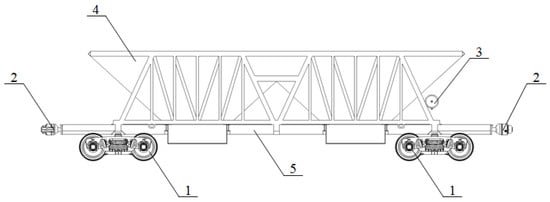
Figure 1.
Two-section hopper wagon: 1—module of the running gear; 2—automatic coupling module; 3—brake equipment module; 4—body module; 5—frame module.
To increase the rigidity of the frame in the areas where the sections are supported on central part, a middle beam of the box section was installed (Figure 2). Due to the fact that the sections were supported not only in the cantilever parts of the frame but also in the middle part, increased stresses and displacements occurred in it. Therefore, a solution was proposed, aimed at increasing the rigidity of the frame by setting beam 6. A patent application has been filed for this design of the wagon.
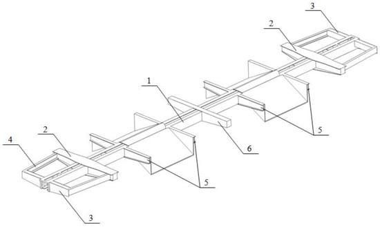
Figure 2.
The frame of a two-section wagon: 1—center girder; 2—pivot beam; 3—end beam; 4—struts; 5—intermediate transverse beams; 6—medium beam.
When carrying this out, the hopper wagon model 20-9749 (Figure 3), built by “Ukrspetsvagon”, was chosen as the prototype. The useful volume of sections of the improved hopper wagon is 41 m3. The wagon has a width of 3154 mm and a length along the frame end beams of 13,500 mm. The wagon base is 7800 mm. An image of the wagon is shown in Figure 4.
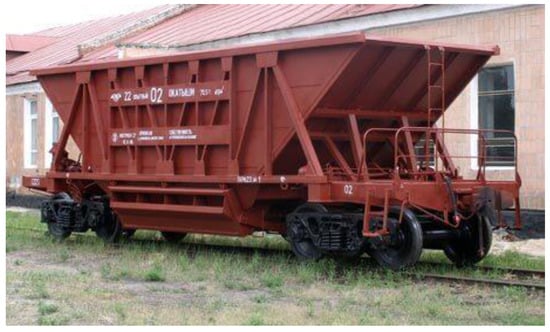
Figure 3.
Hopper wagon.
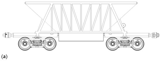
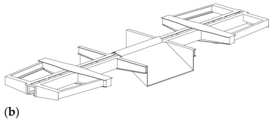
Figure 4.
Finite element model of the hopper wagon frame: (a)—general view; (b)—frame.
To determine the strength of the two-section hopper wagon, a calculation was carried out by using the FEM in the SolidWorks Simulation [28,29]. At the first initial stage of the study, the calculation was made for the first mode (impact). The finite element model of the hopper wagon was formed by isoparametric tetrahedrons (Figure 5). In this case, the grid was created taking into account automatic compaction in areas of possible stress concentrations. Thus, the mesh was uneven relative to the model.
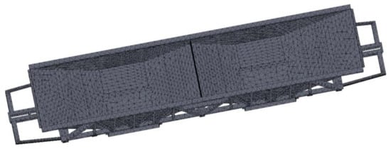
Figure 5.
Finite element model of the hopper wagon.
The number of tetrahedrons was calculated by the graphic and analytic method [30]. The number of mesh elements was 90,457, and the number of nodes was 30,545. The maximum size of a mesh element was 200 mm, and the minimum one was 40 mm. The maximum and minimum sizes of the grid elements were chosen based on the calculations carried out in previous studies by the team of authors regarding other wagon designs. These calculations were confirmed experimentally through field tests. At this stage, based on the experience of previous studies, an identical size of the elements was chosen. In the future, after conducting experimental studies, this hypothesis will be refined.
The calculation scheme of the hopper wagon is shown in Figure 6. The scheme is shown in the section to better visualize the application of loads. When compiling it, the following loads were taken into account: vertical static load Pvst, due to the weight of the cargo; the lateral pressure from the bulk cargo Pl; and the impact load Pimp, the numerical value of which, according to regulatory documents, is 3.5 MN [31]. The limitation of the design scheme is the absence of bulk cargo movements in sections and friction forces between the cargo and walls. The model was fixed by the horizontal parts of the pads. In this case, rigid pinching was used; that is, the friction forces between the center pivot and the female center plates were not taken into account due to their smallness. The calculation was carried out according to the Mises criterion (fourth strength theory). In this case, plastic deformations will take place if the calculated stresses exceed the allowable ones.
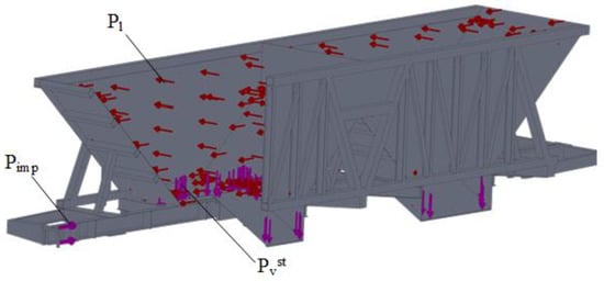
Figure 6.
Calculation scheme of the hopper-wagon-supporting structure.
The pressure of the cargo is determined by [32]
where γ is the density of the cargo, t/m3;
H is the height of the side wall, m;
φ is the angle of the natural slope of the load, rad;
g is the gravitational acceleration, m/s2.
π is a constant that is equal to 3.14.
This formula applies to a vertical wall. In the case of a wall slope, it is necessary to take into account its magnitude. The body material is steel 09G2S. The maximum stresses occurred in the zone of interaction of the center sill with the bolster beam and amounted to 240.7 MPa (Figure 7), which was 30% lower than the allowable one. The yield stress of the structural material equal to 345 MPa was taken into account as a permissible one. The maximum displacements in the structure nodes occurred in the unloading reservoirs and were equal to 8.1 mm (Figure 8).
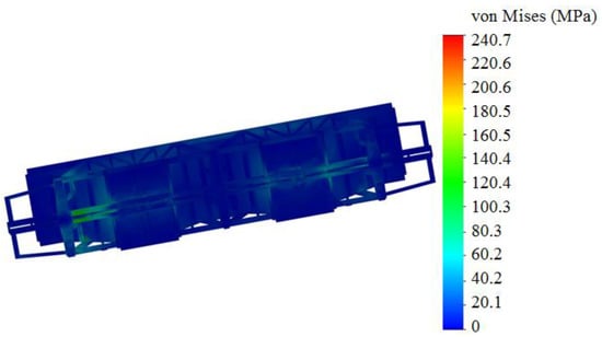
Figure 7.
The stressed state of the hopper.
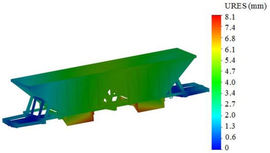
Figure 8.
Displacements in the nodes of the hopper wagon.
The research was also carried out in relation to other calculation modes (Table 1). The stresses were determined on the basis of standard load values for the given operating modes given in the document [31].

Table 1.
Results of calculation of the hopper wagon.
The strength of the hopper wagon under the main operational modes was ensured. Additionally, as part of the study, a thermal calculation of the hopper wagon was carried out, taking into account the transportation of cargo with a temperature of 700 °C [32]. When doing this, the calculation scheme shown in Figure 6 was used, but the calculation did not take into account the longitudinal load on the automatic coupling. Temperature load PT was also applied to the inner surfaces of the sections (Figure 9). This calculation was carried in the SolidWorks Simulation, which implements thermal analysis. An appropriate temperature was applied to the inner surface of the sections and the material of construction was assigned—steel grade 09G2S. The coefficient of thermal expansion of steel was taken equal to 1.5 × 10⁻⁵ 1/K.
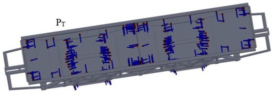
Figure 9.
Scheme of application of temperature load to the hopper-wagon-supporting structure.
The maximum stresses were recorded in the area where the beam was placed and were about 317 MPa (Figure 10). The maximum displacements in the hopper-wagon-supporting structure were about 13.1 mm (Figure 11). Therefore, the strength of the proposed design of the hopper wagon was ensured [32].
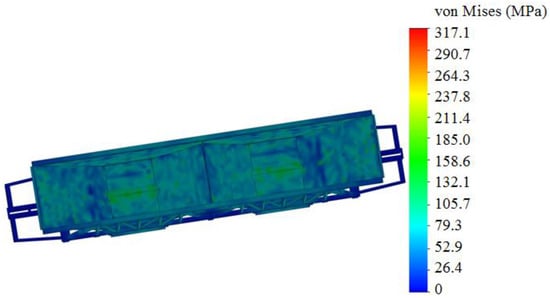
Figure 10.
The stressed state of the hopper wagon.
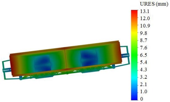
Figure 11.
Displacements in the nodes of the hopper wagon.
5. Determination of the Vertical Load of a Two-Section Hopper Wagon
The purpose of determining the vertical loading of a two-section hopper wagon is to assess the course of its movement by comparing the main dynamics indicators with the normalized ones [32]. Mathematical modeling was carried out to determine the vertical load of the hopper wagon. When performing this, the mathematical model given in the book [33] was used. The model describes the translational and angular movements of the hopper wagon in the vertical plane when it moves along a joint irregularity. At the same time, the track is considered to be elastic and viscous. The calculation scheme is shown in Figure 12. It was taken into account that the wagon moves in an empty state [34,35].
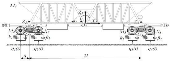
Figure 12.
Calculation scheme.
The model takes into account the technical characteristics of the bogies 18-100.
where M1–M6 are the inertial coefficients of the hopper wagon (body and two bogies); for mass, these coefficients are measured in t; and for the moments of inertia—t∙m2; Cij is a characteristic of the elasticity of the oscillating system components, кN/m; Bij is a scattering function; a is the half length of the bogie wheelbase, кN∙s/m; l is the wagon semi-base, m; δ is a deformation of elastic elements of spring suspension, m; η—roughness of the railway track, m; qi is generalized coordinates; ki is a stiffness of spring suspension of bogies, кN/m; βi is a damping coefficient, кN∙s/m; and FFR is the friction force arising in the spring assembly, kN.
The boundary condition of the mathematical model (2)–(7) is the absence of cargo displacements in the body.
When carrying out the calculation, it was taken into account that the weight of the supporting structure of the wagon with the load was about 730 kN, and the weight of the bogies (model 18-100) was 47 kN. The rigidity of the spring suspension was 8000 kN/m, and the coefficient of relative friction was 0.1. The rigidity of the track was assumed to be 100,000 kN/m; the damping coefficient was 200 kN s/m. The amplitude of the roughness was 0.01 m, the length of the roughness was 3 m; and the distance between the roughnesses was 25 m [33].
The solution of the mathematical model (2)–(7) was carried out by using the Runge–Kutta method in the MathCad software. The initial displacements and velocities were assumed to be zero [36,37,38]. The obtained dynamics indicators (Figure 13, Figure 14, Figure 15 and Figure 16) were within the permissible limits [31]. Accelerations acting on the supporting structure in the center of mass were 5.2 m/s2 (0.53 g), and accelerations in the zones of the frame support on the bogies were equal to 8.4 m/s2 (0.86 g). The forces acting in the spring suspension of the bogies amounted to 42.7 kN. The coefficient of vertical dynamics was equal to 0.6.
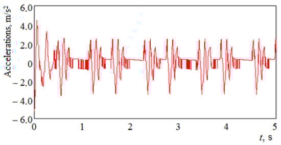
Figure 13.
Acceleration in the center of mass of the hopper wagon.
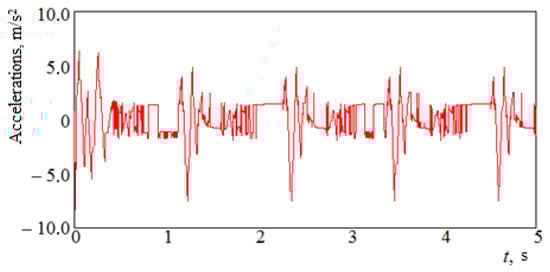
Figure 14.
Acceleration of the hopper-wagon-bearing structure in the areas of support on the bogies.
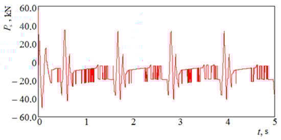
Figure 15.
Forces in spring suspension.
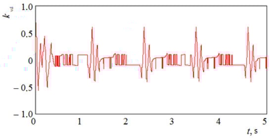
Figure 16.
Coefficient of vertical dynamics.
The normalized value of acceleration at the center of mass of a wagon moving in an empty state with a rail track for the “good movement” mode is 0.6 g, and the dynamics coefficient is 0.6 [31].
6. Study of the Two-Section Hopper Wagon Load during Transportation by Railway Ferry
In order to make it possible to transport the hopper wagon by railway ferries in international traffic, it is suggested to use units for the fastening chain (Figure 17, Figure 18 and Figure 19).
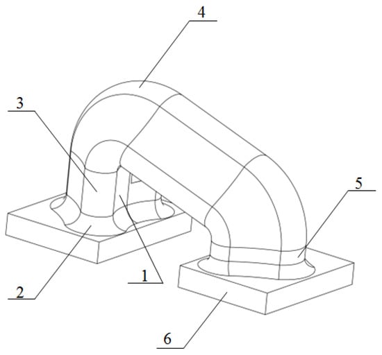
Figure 17.
Unit for fixing the wagon: 1—hook guide; 2—radial tide; 3—cylindrical part; 4—prismatic part; 5—technological strengthening; 6—bearing part.
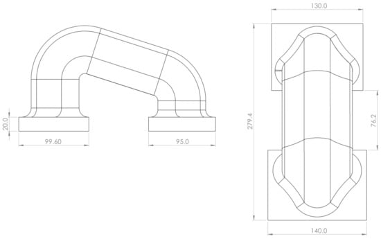
Figure 18.
The basic dimensions of the unit for fastening the wagon.
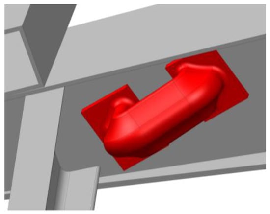
Figure 19.
Placement of the unit on the beam bolster of the wagon.
To ensure the appropriate stiffness of the bolster beam in the areas where the unit was located, it was possible to install reinforcing diaphragm plates in it. Mathematical modeling was carried out to determine the dynamic load of the hopper wagon. The case of side rocking was taken into account (Figure 20).
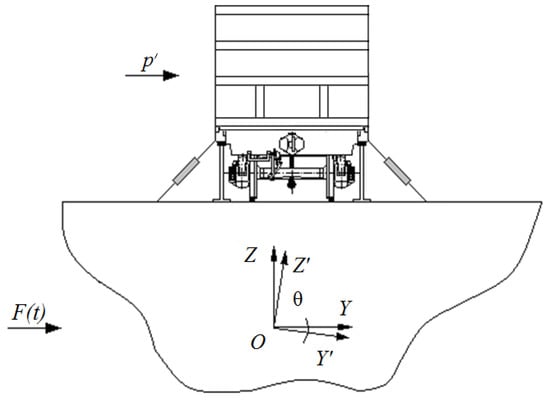
Figure 20.
Calculation scheme.
The authors used a mathematical model developed in their previous works [39]:
where D is the weight of water displacement of the ship, kN; B is the ship’s width, m; h is the ship’s height, m; Λθ is a vibration resistance coefficient, kN∙s/m; zg is a coordinate of the gravity center of the railway ferry, m; p′ is the wind force on the ship’s side view, kN; and F(t) is the law of action of the force that disturbs the movement of a ship, m.
The mathematical model (9) was solved in Mathcad. When doing this, the Runge—Kutta method was applied [40,41]. The initial conditions were assumed to be zero [42,43,44]. The research was carried out in relation to the ship “Heroes of Shipka”, which moves through the waters of the Black Sea. The parameters of the water area of the railway ferry were determined on the basis of the reference literature [45]. The results of the calculations showed that the maximum accelerations relative to the regular place of the wagon on the deck occurred at course angles of the wave 60° and 120° in relation to the hull of the railway ferry and amounted to 0.4 m/s2 (Figure 21).
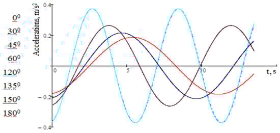
Figure 21.
Accelerations that act on the hopper wagon.
The results of the calculations established that the total amount of acceleration acting on the hopper-wagon-supporting structure was equal to 2.4 m/s2 (0.24 g). At the same time, the total amount of acceleration was defined as the sum of accelerations that act relative to the regular place of the wagon on the deck and the horizontal component of gravitational acceleration caused by the roll angle of the railway ferry.
Analyzing the obtained results, it can be noted that for the heading angles of the wave 0° and 180°, 30° and 150°, 45° and 135°, and 60° and 120°, the accelerations coincided. Therefore, the graph shows four curves.
When calculating the strength of the hopper wagon, the acceleration of 0.24 g was taken into account. When developing the finite element model of the hopper wagon, the number of mesh elements was 1,091,001, and the number of nodes was 356,047. The maximum size of the mesh element was 40 mm; the minimum one was 8 mm.
The model was fastened to the horizontal parts of the frame center pivots, as well as in the areas of body support on mechanical stop-jacks—the area of interaction of the vertical rack with the pivot beam. At the same time, rigid fixing was used.
The calculation scheme of the hopper wagon-bearing structure took into account the following loads: vertical static load Pvst, due to the weight of the load; the lateral pressure from bulk cargo Pl; and the load from the chain binders Pchb (Figure 22). In view of the fact that the wagon was considered as an attached mass with respect to the deck, the resulting acceleration relative to its regular place was taken into account when determining the dynamic load acting on it. This load was taken into account when determining the pressure of the expansion of bulk cargo on the wagon body, as well as in the areas of its interaction with chain ties. Since the case of the ship’s rolling was taken into account, it was taken into account that the ties were tightened on one side of the body, and weakened on the other. On the tension side of the ties, the loads that acted on the body took into account the dynamic component, and on the weakening side, only the load from the initial tension of the tie, which was 50 kN.
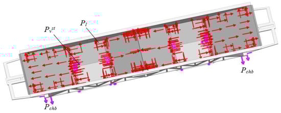
Figure 22.
Calculation scheme of the hopper wagon.
As a result of the spatial placement of the chain binder, the load on the fastening node through it was distributed into components (Figure 23). When performing this, the maximum stresses were 312.3 MPa and occurred in the node for fastening (Figure 24). The performed calculations showed that the strength of the proposed design of the hopper wagon was ensured [31]. The maximum displacements also occurred in the fastening unit and were equal to 9.2 mm (Figure 25).
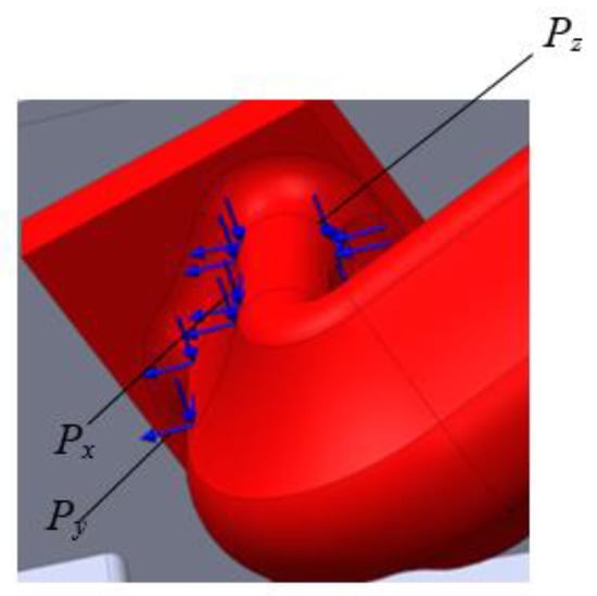
Figure 23.
Scheme of applying loads to a unit for fastening.
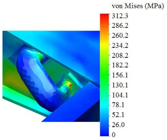
Figure 24.
The stress state of the unit for fastening.
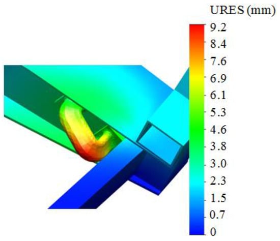
Figure 25.
Displacements in the node to secure the hopper wagon on the deck.
The next stage of these studies is the experimental determination of the strength indicators of the proposed wagon design. This is planned to be carried out through the similarity method in the laboratory using a reduced layout of the wagon model. Such tests also make it possible to verify the generated wagon-loading models under the considered operating conditions.
7. Conclusions
1. Strength analysis of a two-section hopper wagon under the main operational load modes was carried out. The maximum stresses in the hopper wagon occurred in the first design mode (impact) and amounted to 240.7 MPa, which was 30% lower than the allowable one.
The thermal calculation of the two-section hopper wagon was carried out, taking into account the transportation of cargo with a temperature of 700 °C. The results of the calculations showed that the maximum stresses recorded in the area of the beam were about 317 MPa. Therefore, the strength of the proposed wagon design was ensured.
2. The vertical load capacity of a two-section hopper wagon was determined. The accelerations acting on the supporting structure in the center of mass were 5.2 m/s2. The coefficient of vertical dynamics was equal to 0.6. The wagon movement was evaluated as “good”.
3. The two-section hopper wagon load during transportation by sea was studied. The total amount of acceleration acting on the hopper-wagon-supporting structure was equal to 2.4 m/s2 (0.24 g).
The strength of the two-section hopper wagon was calculated. The maximum stresses were 312.3 MPa and occurred in the fastening node. However, the obtained stress values did not exceed the normative ones and were 9.5% lower than them.
The results of the research will contribute to increasing the profitability of railway transport. Additionally, the results of the work can be useful in the creation of modern designs of wagons, including for international traffic.
Author Contributions
Conceptualization A.L.; methodology, G.V. and A.L.; software, A.L.; validation, G.V., A.L. and J.G.; investigation, O.F., A.L. and K.K.; resources, O.F., A.L. and K.K.; writing—original draft preparation, G.V., A.L., K.K. and Y.F.; writing—review and editing J.G.; visualization, G.V., A.L. and K.K.; supervision, J.G. All authors have read and agreed to the published version of the manuscript.
Funding
This publication was issued thanks to support from the Cultural and Educational Grant Agency of the Ministry of Education of the Slovak Republic in the project “Implementation of modern methods of computer and experimental analysis of properties of vehicle components in the education of future vehicle designers” (Project No. KEGA 036ŽU-4/2021). This research was also supported by the Slovak Research and Development Agency of the Ministry of Education, Science, Research and Sport of the Slovak Republic in Educational Grant Agency of the Ministry of Education of the Slovak Republic in the project and VEGA 1/0513/22 “Investigation of the properties of railway brake components in simulated operating conditions on a flywheel brake stand”. The authors also gratefully acknowledge funding from the specific research on “Innovative principles for creating resource-saving structures of railroad cars based on the refined dynamic loads and functionally adaptive flash-concepts”, which was funded from the state budget of Ukraine in 2020.
Institutional Review Board Statement
Not applicable.
Informed Consent Statement
Not applicable.
Data Availability Statement
Not applicable.
Conflicts of Interest
The authors declare no conflict of interest.
References
- Gubarevych, O.; Goolak, S.; Daki, O.; Tryshyn, V. Investigation of Turn-to-Turn Closures of Stator Windings to Improve the Diagnostics System for Induction Motors. Probl. Energeticii Reg. 2021, 2, 10–24. [Google Scholar] [CrossRef]
- Goolak, S.; Tkachenko, V.; Sapronova, S.; Lukoševičius, V.; Keršys, R.; Makaras, R.; Liubarskyi, B. Synthesis of the Current Controller of the Vector Control System for Asynchronous Traction Drive of Electric Locomotives. Energies 2022, 15, 2374. [Google Scholar] [CrossRef]
- Goolak, S.; Tkachenko, V.; Šťastniak, P.; Sapronova, S.; Liubarskyi, B. Analysis of Control Methods for the Traction Drive of an Alternating Current Electric Locomotive. Symmetry 2022, 14, 150. [Google Scholar] [CrossRef]
- Senko, V.I.; Pigunov, A.V.; Afanasiyev, P.M.; Shestakov, C.B. Improving the body structure of the hopper car for the transportation of cement. J. Bull. P.O. Sukhoi Gomel State Tech. Univ. 2017, 2, 3–10. [Google Scholar]
- Afanasiyev, E.V.; Bityutskiy, N.A.; Tsyganskaya, L.V.; Ispolova, E.A.; Filippova, I.O. Fleet of hopper cars renewal designed to transport carbon. Sci. Peer-Rev. J. Proc. Petersburg Transp. Univ. 2019, 1, 37–50. [Google Scholar]
- Tsunami Gate Wagon to Make a Splash at Railway Interchange. Railway Gazette, 11 September 2019.
- Yuan, Y.Q.; Li, Q.; Ran, K. Analysis of C80B Wagons Load-Stress Transfer Relation. Appl. Mech. Mater. 2012, 148–149, 331–335. [Google Scholar] [CrossRef]
- Yoon, S.C.; Kim, G.K.; Jeon, C.S.; Choe, K.Y. Evaluation of Structural Strength in Body Structure of Freight Car. Key Eng. Mater. 2010, 417–418, 181–184. [Google Scholar] [CrossRef]
- Pɫaczek, M.; Wróbel, A.; Buchacz, A. A concept of technology for freight wagons modernization. IOP Conf. Ser. Mater. Sci. Eng. 2016, 161, 012107. [Google Scholar] [CrossRef]
- Fomin, O.; Lovska, A.; Skliarenko, I.; Klochkov, Y. Substantiating the optimization of the loadbearing structure of a hopper car for transporting pellets and hot agglomerate. East.-Eur. J. Enterp. Technol. 2020, 1, 65–74. [Google Scholar]
- Fomin, O.; Vatulia, G.; Lovska, A. Formation of flash-concept for a resource-saving articulated hopper car to transport hot pellets and agglomerate. E3S Web Conf. 2020, 166, 07002. [Google Scholar] [CrossRef]
- Ushakov, A.E.; Safonov, A.A.; Sergeichev, I.V.; Fedulov, B.N.; Kornienko, E.I.; Timofeev, M.A.; Izotov, A.V.; Klenin, Y.G.; Rozin, N.V. Design and optimization of a vacuum infusion technological process for hopper car fabrication using polymeric composite materials. J. Mach. Manuf. Reliab. 2015, 44, 276–282. [Google Scholar] [CrossRef]
- Al-Sukhon, A.; ElSayed, M.S.A. Design optimization of hopper cars employing functionally graded honeycomb sandwich panels. Proc. Inst. Mech. Eng. Part F J. Rail Rapid Transit 2021, 236, 920–935. [Google Scholar] [CrossRef]
- Lee, W.G.; Kim, J.S.; Sun, S.J.; Lim, J.-Y. The next generation material for lightweight railway car body structures: Magnesium alloys. Proc. Inst. Mech. Eng. Part F J. Rail Rapid Transit 2016, 232, 25–42. [Google Scholar] [CrossRef]
- Lee, H.A.; Jung, S.B.; Jang, H.H.; Shin, D.-H.; Lee, J.U.; Kim, K.W.; Park, G.-J. Structural-optimization-based design process for the body of a railway vehicle made from extruded aluminum panels. Proc. Inst. Mech. Eng. Part F J. Rail Rapid Transit 2015, 230, 1283–1296. [Google Scholar] [CrossRef]
- Wennberg, D.; Stichel, S.; Wennhage, P. Substitution of corrugated sheets in a railway vehicle’s body structure by a multiple-requirement based selection process. Proc. Inst. Mech. Eng. Part F J. Rail Rapid Transit 2012, 228, 143–157. [Google Scholar] [CrossRef]
- Molavitabrizi, D.; Laliberte, J. Methodology for multiscale design and optimization of lattice core sandwich structures for lightweight hopper railcars. Proc. Inst. Mech. Eng. Part C J. Mech. Eng. Sci. 2020, 234, 4224–4238. [Google Scholar] [CrossRef]
- Fomin, O.; Lovska, A. Determination of dynamic loading of bearing structures of freight wagons with actual dimensions. East.-Eur. J. Enterp. Technol. 2021, 2, 6–15. [Google Scholar] [CrossRef]
- Vatulia, G.; Lovska, A.; Pavliuchenkov, M.; Nerubatskyi, V.; Okorokov, A.; Hordiienko, D.; Vernigora, R.; Zhuravel, I. Determining patterns of vertical load on the prototype of a removable module for long-size cargoes. East.-Eur. J. Enterp. Technol. 2022, 6, 21–29. [Google Scholar] [CrossRef]
- Antipin, D.Y.; Racin, D.Y.; Shorokhov, S.G. Justification of a Rational Design of the Pivot Center of the Open-top Wagon Frame by means of Computer Simulation. Procedia Eng. 2016, 150, 150–154. [Google Scholar] [CrossRef]
- Prakash, S.C.; Bharti, P.K. Study and Analysis of Doors of BCNHL Wagons. Int. J. Eng. Res. Technol. IJERT 2015, 4, 1195–1200. [Google Scholar]
- Patrascu, A.I.; Hadar, A.; Pastrama, S.D. Structural Analysis of a Freight Wagon with Composite Walls. Mater. Plast. 2019, 57, 140–151. [Google Scholar] [CrossRef]
- Street, G.E.; Mistry, P.J. Michael Sylvester Johnson. Impact Resistance of Fibre Reinforced Composite Railway Freight Tank Wagons. J. Compos. Sci. 2021, 5, 152. [Google Scholar] [CrossRef]
- Kosobudzki, M.; Jamroziak, K.; Bocian, M.; Kotowski, P.; Zając, P. The analysis of structure of the repaired freight wagon. AIP Conf. Proc. 2018, 2029, 020030. [Google Scholar] [CrossRef]
- Płaczek, M.; Wróbel, A.; Olesiejuk, M. Modelling and arrangement of composite panels in modernized freight cars. MATEC Web Conf. 2017, 112, 06022. [Google Scholar] [CrossRef]
- Fomin, O.; Lovska, A.; Kulbovskyi, I.; Holub, H.; Kozarchuk, I.; Kharuta, V. Determining the dynamic loading on a semi-wagon when fixing it with a viscous coupling to a ferry deck. East.-Eur. J. Enterp. Technol. 2019, 2, 6–12. [Google Scholar] [CrossRef]
- Fomin, O.; Gorbunov, M.; Gerlici, J.; Lovska, A.; Kravchenko, K. Dynamics and strength of circular tube open wagons with aluminum foam filled center sills. Materials 2021, 14, 1915. [Google Scholar] [CrossRef] [PubMed]
- Alyamovskij, A.A. SolidWorks/COSMOSWorks 2006–2007. Engineering Finite Element Analysis; Series “Design”; DMK: Moscow, Russia, 2007; 784p. [Google Scholar]
- Alyamovskij, A.A. COSMOSWorks. Fundamentals of Structural Analysis in SolidWorks; Series “Design”; DMK: Moscow, Russia, 2010; 784p. [Google Scholar]
- Vatulia, G.L.; Petrenko, D.H.; Novikova, M.A. Experimental estimation of load-carrying capacity of circular, square and rectangular CFTS columns. J. Nauk. Visnyk Natsionalnoho Hirnychoho Univ. 2017, 6, 97–102. [Google Scholar]
- DSTU 7598:2014; Freight Wagons. General Requirements for Calculations and Design of New and Modernized Wagons of 1520 mm Track (Non-Self-Propelled). UkrNDNTS: Kiev, Ukraine, 2015; 162p.
- Lukin, V.V.; Shadur, L.A.; Koturanov, V.I.; Hohlov, A.A.; Anisimov, P.S. Design and Calculation of Wagons; UMK MPS: Moskov, Russia, 2000; 731p. [Google Scholar]
- Domin, Y.V.; Chernyak, G.Y. Basics of Wagon Dynamics; Kyiv University of Economics and Transport Technology: Kyiv, Ukraine, 2003; 269p. [Google Scholar]
- Fomin, O.; Gerlici, J.; Gorbunov, M.; Vatulia, G.; Lovska, A.; Kravchenko, K. Research into the Strength of an OpenWagon with Double Sidewalls Filled with Aluminium Foam. Materials 2021, 14, 3420. [Google Scholar] [CrossRef]
- Krol, O.; Porkuian, O.; Sokolov, V.; Tsankov, P. Vibration stability of spindle nodes in the zone of tool equipment optimal parameters. Comptes Rendus De L’acade’mie Bulg. Des Sci. 2019, 72, 1546–1556. [Google Scholar] [CrossRef]
- Nalapko, O.; Shyshatskyi, A.; Ostapchuk, V.; Mahdi, Q.A.; Zhyvotovskyi, R.; Petruk, S.; Lebed, Y.; Diachenko, S.; Velychko, V.; Poliak, I. Development of a method of adaptive control of military radio network parameters. East.-Eur. J. Enterp. Technol. 2021, 1, 18–32. [Google Scholar] [CrossRef]
- Panchenko, S.; Vatulia, G.; Lovska, A.; Ravlyuk, V.; Elyazov, I.; Huseynov, I. Influence of structural solutions of an improved brake cylinder of a freight car of railway transport on its load in operation. EUREKA Phys. Eng. 2022, 6, 45–55. [Google Scholar] [CrossRef]
- Lovskaya, A. Assessment of dynamic efforts to bodies of wagons at transportation with railway ferries. East.-Eur. J. Enterp. Technol. 2014, 3, 36–41. [Google Scholar] [CrossRef]
- Lovska, A.; Fomin, O.; Pistek, V.; Kucera, P. Dynamic load and strength determination of carrying structure of wagons transported by ferries. J. Mar. Sci. Eng. 2020, 8, 902. [Google Scholar] [CrossRef]
- Kiryanov, D.V. Mathcad 13; BHV-Petersburg: St. Petersburg, Russia, 2006; 608p. [Google Scholar]
- Dyakonov, V. MATHCAD 8/2000: A Special Guide; Piter: St. Petersburg, Russia, 2000; 592p. [Google Scholar]
- Fomin, O.; Gerlici, J.; Vatulia, G.; Lovska, A.; Kravchenko, K. Determination of the Loading of a Flat Rack Container during Operating Modes. Appl. Sci. 2021, 11, 7623. [Google Scholar] [CrossRef]
- Krol, O.; Sokolov, V. Modeling of Spindle Node Dynamics Using the Spectral Analysis Method. Lect. Notes Mech. Eng. 2020, 1, 35–44. [Google Scholar] [CrossRef]
- Panchenko, S.; Gerlici, J.; Vatulia, G.; Lovska, A.; Pavliuchenkov, M.; Kravchenko, K. The Analysis of the Loading and the Strength of the FLAT RACK Removable Module with Viscoelastic Bonds in the Fittings. Appl. Sci. 2023, 13, 79. [Google Scholar] [CrossRef]
- Reference Data on the Regime of Wind and Waves of the Baltic, Northern, Black, Azov and Mediterranean Seas. Russian Maritime Register of Shipping. Available online: https://files.stroyinf.ru/Data2/1/4293747/4293747775.pdf (accessed on 28 July 2021).


Disclaimer/Publisher’s Note: The statements, opinions and data contained in all publications are solely those of the individual author(s) and contributor(s) and not of MDPI and/or the editor(s). MDPI and/or the editor(s) disclaim responsibility for any injury to people or property resulting from any ideas, methods, instructions or products referred to in the content. |
© 2023 by the authors. Licensee MDPI, Basel, Switzerland. This article is an open access article distributed under the terms and conditions of the Creative Commons Attribution (CC BY) license (https://creativecommons.org/licenses/by/4.0/).