Abstract
Millions of contaminated sites worldwide need to be remediated to protect the environment and human health. Although numerous remediation technologies have been developed, selecting optimal technologies is challenging. Several multiple criteria decision-making methods for screening the optimal remediation technology have been proposed, but they mostly focus on a specific area rather than the whole contaminated site. In recent years, the “contamination source control—process blocking—in situ remediation” technology mix model has gradually gained high appreciation. Nevertheless, the screening of technologies within each chain of this model relies heavily on arbitrary personal experience. To avoid such arbitrariness, a petroleum-contaminated site containing light non-aqueous phase liquids (LNAPLs) was used as an example, and a scientific screening and combination procedure was developed in this study by considering the distribution characteristics of contaminants. Through the procedure, a technology mix, which includes institutional control, risk monitoring, emergency response, multiphase extraction, interception ditch, monitoring of natural attenuation, hydrodynamic control, as well as some alternative technologies, was found, aiming at different locations and strata. The clear spatial relationship concept promises to enhance the effectiveness of contaminated site remediation. The proposed method only gave us a technical framework and should be tested and enriched in future studies.
1. Introduction
Contaminated sites and the environmental problems they bring are issues of major global concern. Taking petrochemical sites as an example, Europe and the US have approximately 342,000 and 200,000 petrochemical-contaminated sites, respectively [1]. China has approximately 120,000 filling stations, 300 refineries, and bulk factories occupying 78 million m3 in our previous statistics in 2020. The soil and groundwater at these sites are all laden with potential contaminants. The US EPA and other national environmental agencies emphasize that contaminated sites must be remediated in order to restore and protect groundwater resources, and thereby create a safe living or working environment [2,3].
There are many types of contaminated site remediation technologies. For instance, nearly 30 soil and groundwater contamination remediation and control technologies have been used in the remediation of the 1468 Superfund sites in the US [4,5,6]. The List of Contaminated Site Remediation Technologies (first batch) issued by China in 2014 lists 15 types of remediation and risk control technologies [7]. In most cases, these techniques have commonly been evaluated by experienced experts, but different technologies are often selected because they are familiar but not because they are the most applicable or cost-effective for a given site [8].
To emilite the arbitrary technology selection, several multiple criteria decision-making methods, including simple additive weighting (SAW), ordered weighted average (OWA), analytic hierarchy process (AHP), preference ranking organization method for enrichment evaluation (PROMETHEE), and technique for order preference by similarity to ideal solution (TOPSIS), have been used to screen the optimal technology [8,9,10,11,12,13].
These screening processes for remediation methods mainly focus on specific areas of contaminated sites, with technologies primarily selected or ruled out based on the type of contaminants, stratigraphy, and petrology [14,15,16,17]. However, contaminants in the soil and aquifers can migrate with groundwater flow [18], leading to variations in contaminants over time and space. Depending on the phase and concentration distribution of contaminants in different areas, contaminated areas or strata at a site can be classified as the contamination source zone and contamination plume [19]. The undifferentiated treatment of different strata and vague spatial delineation of remediation technology application tend to overlook the inhomogeneous and dynamic distribution of contaminants across sites, probably result in the excessive remediation of certain areas or post-remediation reappearance of contamination, and are not consistent with a precise and scientific control system.
In the currently recognized remediation framework, the ultimate goal is to prevent potential receptors from being contaminated or restore receptor risks within acceptable limits [20]. Therefore, within this framework, we only need to protect the receptors without considering non-receptors. However, in order to protect the receptors effectively, every link that contributes to receptor contamination should be taken into account. This means that when selecting remediation technologies, we should consider the entire chain of contamination—source zone, plume, and receptors—as a whole. Based on this understanding, researchers have recently proposed and lent widespread support to the “contamination source control—process blocking—in situ remediation” technology mix model [21,22,23]. However, the screening of technologies under the technology mix model is largely reliant on empirical methods, and the model lacks a scientific screening method of the combinatorial system.
To develop a valid site remediation technology mix method matching the “contamination source control—process blocking—in situ remediation” technology mix model, in the study, a petrochemical-contaminated site was set as an example. Based on the site contaminant distribution characteristics, and clear-cut “contamination source zone- plume—potentially contaminated area” linkage, an integrated site remediation technology mix method with a clear spatial relationship concept was established.
2. Materials and Methods
2.1. Technology Mix Method
Based on the site’s contaminant distribution characteristics, we adopt the “contamination source control—process blocking—in situ remediation” technology mix concept and then establish a list of remediation technologies classified by area in keeping with the standards and guidelines issued by various countries’ environmental agencies. After performing an assessment and ranking of each technology from technological, environmental, and social perspectives, we optimize the technology mix in accordance with ranking results, which yields a solution with an optimized technology mix. The specific steps include:
- (1)
- Clarification of the contamination source zone, plume area, and formation process
Based on a site survey or collection of data, determine the site’s chief contaminant types and their distribution characteristics, analyze the hydrological and geological data including the site’s strata, lithology, and water table, and establish a conceptual model of the contaminant’s hydrological and geological characteristics. Identify the contamination source (including site contamination source and groundwater contamination source), contamination plume, and potentially contaminated area within the site and the peripheral area based on contaminant concentration or phase, and predict the contamination pathways.
Taking a site contaminated with non-aqueous phase liquids (NAPLs) as an example, the groundwater contamination source can be defined as the area containing NAPLs, the contamination plume can be defined as the area in which contaminants exist as a soluble phase [24], and the potentially contaminated area can be defined as the area of concern, i.e., the area which has not yet been contaminated, but which may be contaminated in the future.
- (2)
- Establishment of a list of classified remediation technologies
In accordance with the contaminated source zone, plume area, potentially contaminated area, and contamination pathways identified in Step 1, analyze each area’s contamination control and prevention needs on the basis of remediation requirements and assess whether the migration of contaminants between different areas must be controlled. Determine the technologies that can be used for site remediation, including but not limited to source control, process blocking, contamination plume in situ remediation, and other assisting technologies. Generally, in the source zone, source control technologies can be selected; in the plume area, in-suit technologies can be selected; process blocking technologies are mainly used to block the contaminants migrating from the source zone to the plume area, and the plume area to the potentially contaminated area. Then, collect specific feasible contamination remediation techniques based on the foregoing technology types. It should also be noted that a certain specific remediation technique can be associated with multiple technologies.
- (3)
- Assessment of the classified remediation technologies
Use assessment methods such as decision-making support system [25] and multicriteria decision system [26] to assess and rank specific contaminated source control, process blocking, and contamination plume in situ remediation technologies in accordance with technological, environmental, and social indicators.
Technological indicators chiefly consider technological feasibility. Assessment is generally performed on the basis of a hydrological and geological conceptual model of site contamination and reflects technological principles and applicable conditions. The applicability of site contaminant characteristics, stratigraphy, lithology, contamination strata, and water table conditions is then assigned points, where full applicability is assigned 3 points, basic applicability 2 points, conditional applicability 1 point, and no applicability 0 points. A sample site condition assessment matrix is shown in Table 1. The specific number of points assigned for each condition will reflect the actual contaminated site and contaminant types.

Table 1.
Meaning of technological indicators for site contamination control technologies and scoring standards.
Environmental indicators chiefly consider the impact of the remediation technologies on peripheral safety and the environment during the design, construction, operation, and maintenance processes. These indicators consist of safety, environmental friendliness, low resource/energy consumption, and sustainability. See Table 2 for the content and assessment standards for each indicator. High, moderate, and low are assigned respective scores of 3 points, 2 points, and 1 point.
Table 2.
Meaning of environmental indicators for site contamination control technologies and scoring standards.
Social indicators chiefly consider the feasibility of technology implementation. The indicators shown below have been adapted and revised from the guidelines in the contaminated site remediation technology screening matrix issued by the US Department of Defense Environmental Technology Transfer Committee (DOD ETTC) [27], and chiefly consist of the five aspects, including technological maturity, social acceptability, technology complexity, time frame, and capital investment. The content and scoring standards of each indicator are shown in Table 3.
Table 3.
Meaning of social indicators for site contamination control technologies and scoring standards [27].
Among the technological, environmental, and social indicators, technological indicators are the most fundamental; if a technology is completely infeasible (a score of 0), no further assessment will be conducted.
In the assessment standard tables, the technology’s resource/energy consumption among environmental indicators and economic cost among social indicators should be “equivalent to that of other comparable technologies.” As a consequence, the same remediation technology may have different final scores in different contaminated areas. For example, although multiple extraction technologies can be applied to contamination source and contamination plume areas when compared with such other technologies as natural attenuation and enhanced bioremediation, its economic cost is relatively high when applied to the contamination plume, giving it a lower score, but its economic cost is relatively low when applied to contamination source areas, giving it a higher score.
- (4)
- Preferred technology mix: Follow the principle of “optimize each item, seek mutual compatibility; if not compatible, score again.”
The implementation process involves the selection of optimal technologies from source control, process blocking, and in situ remediation technologies, and the assessment of their mutual compatibility; if they are compatible, they constitute an optimal solution. A compatible technology mix implies that the implementation of these technologies in tandem will not affect the original scores of these technologies in Step 3; if the implementation of any one technology causes changes in environmental conditions, which makes it impossible to satisfy the conditions for use of another remediation technology, or if it causes the technological, environmental, or social suitability of another technology in the mix to decrease, then the implemented technology does not meet the requirement for compatibility. For instance, the implementation of certain chemical oxidation technologies may affect the activity of microbes within an aquifer [28], which will cause the suitability of natural attenuation and microbial augmentation methods to decline. This implies that chemical oxidation technology is incompatible with the natural attenuation and microbial augmentation methods.
If optimal technologies are not compatible, continued screening should be performed via the following two approaches: (1) sequentially substitute suboptimal technologies in a certain item and re-assess compatibility, until mutual compatibility has been achieved; then calculate the total score for the compatible technologies; (2) re-assess the score of each technology of other types in Step 3 after changing the implementation conditions of an incompatible technology, select the optimal mix, and calculate the total score. Compare the total scores in (1) and (2) and take the mix with the highest score as the optimal solution.
2.2. Site Situation
The case site consists of the gasoline and diesel tank area at a certain in-production refining enterprise on the mid-stream section of China’s Yangtze River. The tank area rests on a 1–2 m layer of fill; an approximately 5 m layer of silty clay lies below the fill, with a layer of fine sand in some places; a roughly 20 m layer of fine sand lies below this layer; the fine sand layer is underlain by clay. The water table lies 2–3 m below the surface. The aquifer has a classic floodplain binary structure, with the upper portion consisting of a silty clay phreatic aquifer and the lower portion consisting of an underlying fine sand micro-confined aquifer, where the clay layer below the aquifer can be considered an impermeable layer. The main groundwater flow direction is from south to north. Contaminants at the site chiefly consist of petroleum hydrocarbons, and contaminants consisting of light non-aqueous phase liquids (LNAPLs) in the form of gasoline and diesel components are present near the water table. A conceptual hydrological and geological model of contamination at the site is shown in Figure 1.
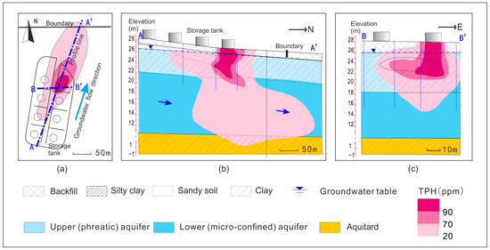
Figure 1.
Conceptual hydrological and geological model of contamination at the case site ((a) is a plan, (b) is a cross-section along A-A′, and (c) is a cross-section along B-B′).
3. Results
3.1. Identification of Contamination Source, Contamination Plume, and Contamination Pathways
It can be seen from the foregoing conceptual model that the source of contamination consists of oil storage tanks, and the source of groundwater contamination consists of the non-aqueous phase petroleum hydrocarbons leaking into the ground from the oil storage tanks. The source area is chiefly located in the clay phreatic aquifer constituting the upper portion of the aquifer, and the contamination plume is largely distributed in the downstream micro-confined fine sand aquifer constituting the lower portion. The potentially contaminated area, namely, the acceptor, chiefly consists of soil and groundwater outside the boundaries of the plant and also includes downstream surface water bodies. The chief contaminant migration pathway consists of the lower micro-confined aquifer.
3.2. Establishment of a Classified Remediation Technology List
In accordance with the results of the assessment in Step 1, since a source of contamination and source of groundwater contamination existed at the site, it was necessary to eliminate the source in order to prevent the continued leakage of contamination; the pathway by which contamination would migrate into the potentially contaminated area could be obstructed by process blocking, and the lower micro-confined aquifer is the chief migration strata of contaminant migration which requires key point control; if the risk that the contamination plume would still contaminate the potentially contaminated area continue to exist after eliminating the source and blocking pathways, in situ remediation of the contamination plume could be performed. Since the contaminant chiefly migrated vertically in the vadose zone, and the migration of contaminant into the groundwater aquifer might cease after the site’s contamination source was eliminated, so that contaminant would have almost no effect on the potentially contaminated area, contamination of the vadose zone could be ignored for the time being. Based on this understanding, remediation of the site could employ the following approaches: site source control, groundwater contamination source elimination, process blocking (of contaminant migration in the lower micro-confined aquifer), and in situ remediation of the contamination plume. We consequently gathered various usable technological methods (Table 4).
Table 4.
List of petrochemical site contamination control technologies.
3.3. Assessment of the Classified Remediation Technologies
We used a decision-making support system (Figure 2) to assess contaminated source control, process blocking, and in situ remediation technologies in different strata in accordance with technological, environmental, and social indicators (Table 1, Table 2 and Table 3). Addressing this petrochemical site, we referred to the applicable conditions for remediation technologies in the US EPA’s Underground Storage Tank Sites [17]; the resulting technology score matrix is shown in Table 5.

Figure 2.
Technology screening decision-making support system model.
Table 5.
Scoring standards for petrochemical site contamination control technologies.
It is assumed that in this case that technological indicators, environmental indicators, and social indicators are equally important, and the secondary indicators and various links within the technological indicators, environmental indicators, and social indicators are also equally important. If the technological indicator score is 0, it is assumed that the technology is not suitable for this site, and no further assessment will be performed. A summary of assessment results and ranking of contamination source control—process blocking—in situ remediation technologies is shown in Table 6.
Table 6.
Ranking of petrochemical site contamination remediation technologies.
From the table, institutional control, risk source monitoring, and emergency response all gained the full mark. That is because the site is located in an in-production plan, and all the site contamination source control procedures should be carried out. Assisting technologies gained scores of zero, for the remediation work condition was good and no additional assisting technologies were needed.
For other types of technologies, many factors affected the final scores. For example, for process blocking, the upper (phreatic) aquifer, both interception ditch and hydrodynamic control gained higher scores. In environmental factors, they obtained the same score, 2.85 (See Table S1). In social factors, the interception ditch obtained a lower score (2.40) than hydrodynamic control (2.53), for the lower development status of the interception ditch (See Table S2). In technical factors, the interception ditch obtained a higher score (2.50) than the hydrodynamic control (2.25), for the hydrodynamic control is hardly used in clay stratum (See Table S3).
3.4. Preferred Technology Mix
The mix when selecting the technologies ranked first in Table 6 is as follows: site contamination source control technologies consist of institutional control, risk monitoring, and emergency response; for upper phreatic aquifer remediation, the groundwater contamination source control technology consists of multiphase extraction, process blocking technology consists of interception ditch, and in situ plume remediation technology consists of monitoring of natural attenuation; for lower micro-confined aquifer remediation, the groundwater contamination source control technology consists of multiphase extraction, process blocking technology consists of hydrodynamic control, and the in situ plume remediation technology consists of monitoring of natural attenuation. These technologies are mutually compatible, and, therefore, form an optimal technology mix for this site.
4. Discussion
4.1. The Screened Technologies for the Case Site
The screened technologies include institutional control, risk monitoring, emergency response, multiphase extraction, interception ditch, monitoring of natural attenuation, and hydrodynamic control. These technologies have been selected and widely used in managing various contaminated sites [33,34,35,36], but combining these technologies together to remediate one site is seldom performed.
Previous studies always aimed at a certain layer of the aquifer or considered several layers as a whole [37,38,39]. Therefore, there was always only one optimal technology for each location. In the present study site, two aquifer layers have been contaminated. According to the present developed method, the different layers should be treated discriminately, which resulted in the two optimal technologies at one location. For example, for blocking the transportation of contaminates, interception ditch and hydrodynamic control were both selected, but the former is for the upper (phreatic) aquifer and the latter is for the lower (micro-confined) aquifer. The interception ditch is hardly operated when the depth is greater than 15 m and, therefore, was not suitable for the lower aquifer, while in the shallow aquifer, it is easily developed, operated, and maintained [40,41,42], and, therefore, was selected for upper aquifer in the study. The other technology, hydrodynamic control, is not suitable for the clay medium [43] and, therefore, was not been selected for the upper aquifer, but is suitable for the sandy lower (micro-confined) aquifer. Separately treating for different characteristic stratum or contaminant concentrations is the precondition for precise remediation and can avoid ineffective remediation.
In practice, combining more than one technology to remediate contaminated soil and aquifer is not rare [44]. For example, Fenton processes and biotreatment were combined for soil remediation [45]; microbial combined methods, including microbe-biochar, microbe–nutrition, and microbe–plant technologies were used to remediate the petroleum-contaminated soils [46]; a plant–microbial combined bioremediation of polychlorinated naphthalene-contaminated soil was established using the intelligent integration of analytic hierarchy process and formula evaluation methods [47]; a sustainability assessment methodology for prioritizing the technologies of groundwater contamination remediation was established [48]. In comparison, combining multiple techniques to remedy a contaminated site is rare. A classic case is combining five technologies to remediate a PHC site, which was a former gasoline service station located in southwest Ohio [49]. At first, the remediation plan consisted of a combined groundwater pump and treat and soil vapor extraction. However, accompanied by the remediation processes, to meet the requirements, the plan had to be adjusted, and natural attenuation needed to be monitored, so surfactant-based soil washing and catalytic oxidation had been added empirically. The case represents most remediation projects that choosing the techniques is experiential and lacking systematicness. In our study, the contaminated soil and groundwater, as well as the receptors, were deemed as a system, and the techniques can be chosen systematically. Combining with the assessment methods and compatibility evaluation, an effective and reasonable approach is expected to be found.
4.2. Implications
Protecting the receptor is the terminal goal, and, therefore, the screened optimal technology mix does not necessarily include the site’s ultimate remediation technologies; these technologies can be selected after reviewing them in the order of their scores during subsequent effectiveness modeling [50,51]. For instance, in this case study, the preferred in situ contamination plume remediation technology consists of natural attenuation monitoring; if it is found during modeling that natural attenuation monitoring will not yield the desired remediation effects during the period of validity, enhanced bioremediation can be assessed. If funding permits, different types of technology can be employed jointly; the technologies employed jointly can be selected in accordance with their ranking order. This principle can be also used to adjust the technologies during the course of a remediation project, especially when the initially selected technologies may not yield the desired results.
During the technology screening process, attention must be paid to the spatial distribution characteristics of contamination and contamination migration processes in order to clarify the spatial locations and relationships of the contamination source, contamination plume, and potential receiving bodies. In order to enhance the specificity of technology screening, each remediation technology must be assessed on the basis of different standards when used in different contaminated areas or for different remediation links.
Compatibility assessment must be performed for technologies in the preferred technology mix, and a dynamic score adjustment and re-screening plan must be made when technologies are incompatible. The goal is to enhance the compatibility of the remediation mix as a whole and realize an integrated remediation solution.
With regard to the establishment of an easy-to-implement technological and environmental indicators system, the technology score matrix can be used directly in the case of most petrochemical-contaminated sites; in the case of environmental indicators, the safety, environmental friendliness, resource/energy consumption, and sustainability of remediation technologies during the four stages of design, construction, operation, and maintenance can be assessed.
By providing ideas and principles concerning technology screening via classified assessment, the technology screening mix method presented in this paper offers powerful expandability. For example, during the classified assessment of remediation technologies in Step 3, various types of decision-making support systems can be employed, and other screening techniques can be used as well. These methods can be used in a flexible manner in light of the actual situation. The proposed procedure is not only suitable for hydrocarbon-contaminated unconsolidated sediment sites but also suitable for other contaminants and lithologies. When the contaminated sites or conditions vary, we simply need to follow the procedure and construct a new mix.
5. Conclusions
This study proposed a method of screening the optimal technologies for site remediation. The method is rooted in the “contamination source control—process blocking—in situ remediation” site remediation principles and the distribution characteristics of contaminants, as well as relationships among different areas including the source zone, plume area, and potentially contaminated area. The clear spatial relationship concept promises to enhance the effectiveness of contaminated site remediation. When using the procedure in an in-production petrochemical-contaminated site where LNAPLs are present, a technology mix, which includes institutional control, risk monitoring, emergency response, multiphase extraction, interception ditch, monitoring of natural attenuation, hydrodynamic control, as well as some alternative technologies, was found, aiming at different locations and strata. The technologies in the mix may not be the final ones and should be tested using computer simulation or pilot scale tests before carrying out the remediation work. The proposed method only gave us a technical framework and should be tested and enriched in future studies.
Supplementary Materials
The following supporting information can be downloaded at: https://www.mdpi.com/article/10.3390/app131911076/s1, Table S1: The scores in environmental factors; Table S2: The scores in social factors; Table S3: The scores in technical factors.
Author Contributions
Methodology, Z.Z., C.G., L.S. and Z.N.; Software, Y.X. and X.W.; Validation, Y.X. and X.W.; Investigation, S.Y., C.G., L.S. and Z.N.; Resources, Z.Z., C.G. and Z.N.; Data curation, Z.Z., C.G., L.S. and Z.N.; Writing—original draft, M.Z.; Writing—review & editing, M.Z., Z.Z., L.S. and Z.N. All authors have read and agreed to the published version of the manuscript.
Funding
This research was funded by the National Natural Science Foundation of China, grant number 42007171; the Sinopec Science Department Project, grant number 322082; the Hebei Natural Science Foundation, D2022504009; the CAGS Research Fund, grant number SK202207.
Institutional Review Board Statement
Not applicable.
Informed Consent Statement
Not applicable.
Data Availability Statement
The data presented in this study are available on request from the corresponding author.
Conflicts of Interest
Author Shuai Yang, Yan Xie and Xinzhe Wang were employed by the company SINOPEC Research Institute of Safety Engineering Co., Ltd. Author Zhifei Zhang was employed by the company Hebei Geological Environment Monitoring Institute. The remaining authors declare that the research was conducted in the absence of any commercial or financial relationships that could be construed as a potential conflict of interest. The authors declare that this study received funding from Sinopec Science Department Project. The funder was not involved in the study design, collection, analysis, interpretation of data, the writing of this article or the decision to submit it for publication.
References
- U.S. Environmental Protection Agency. Petroleum Brownfields. Available online: https://www.epa.gov/ust/petroleum-brownfields (accessed on 12 July 2023).
- U.S. Environmental Protection Agency. Releases from Underground Storage Tanks; U.S. Environmental Protection Agency: Washington, DC, USA, 2023. [Google Scholar]
- Mitab, B.T.; Hamdoon, R.M.; Sayl, K.N. Assessing potential landfill sites using gis and remote sensing techniques: A case study in kirkuk, iraq. Int. J. Des. Nat. Ecodynamics 2023, 18, 643–652. [Google Scholar]
- Bai, L.P.; Luo, Y.; Liu, L.; Zhou, Y.Y.; Yan, Z.G.; Li, F.S. Research on the screening method of soil remediation technology at contaminated sites and lts application. Huanjing Kexue 2015, 36, 4218–4224. [Google Scholar]
- Khan, F.I.; Husain, T.; Hejazi, R. An overview and analysis of site remediation technologies. J. Environ. Manag. 2004, 71, 95–122. [Google Scholar]
- Hao, G.; Yong, Q.; Yuan, G.X.; Wang, C.X. Research progress on the soil vapor extraction. J. Groundw. Sci. Eng. 2020, 8, 57. [Google Scholar]
- Ministry of Ecology and Environment of the People’s Republic of China. List of Remediation Techniques for Contaminated Sites (First Batch); Ministry of Ecology and Environment of the People’s Republic of China: Beijing, China, 2014. [Google Scholar]
- Tian, J.; Huo, Z.; Ma, F.; Gao, X.; Wu, Y. Application and selection of remediation technology for ocps-contaminated sites by decision-making methods. Int. J. Environ. Res. Public Health 2019, 16, 1888. [Google Scholar]
- Verta, M.; Kiviranta, H.; Salo, S.; Malve, O.; Korhonen, M.; Verkasalo, P.K.; Ruokojärvi, P.; Rossi, E.; Hanski, A.; Päätalo, K. A decision framework for possible remediation of contaminated sediments in the river kymijoki, finland. Environ. Sci. Pollut. Res. 2009, 16, 95–105. [Google Scholar]
- Meng, X.S.; Chen, H.H.; He, Y.-P.; Zheng, C.Q.; Yue, X. Establishment of the environmental indexes in selection of remediation schemes: A case study of an abandoned coking site. Environ. Eng. 2021, 39, 7. [Google Scholar]
- Luo, C.; Yi, A.; Zhang, Z.; Zhao, N.; Wang, Q.; Huang, Q. Remediation technology selection for pops contaminated sites. Chin. J. Environ. Eng. 2008, 2, 569–573. [Google Scholar]
- Bai, L.; Luo, Y.; Shi, D.; Xie, X.; Liu, L.; Zhou, Y.; Yan, Z.; Li, F. Topsis-based screening method of soil remediation technology for contaminated sites and its application. Soil Sediment Contam. Int. J. 2015, 24, 386–397. [Google Scholar]
- Chen, R.; Teng, Y.; Chen, H.; Yue, W.; Su, X.; Liu, Y.; Zhang, Q. A coupled optimization of groundwater remediation alternatives screening under health risk assessment: An application to a petroleum-contaminated site in a typical cold industrial region in northeastern china. J. Hazard. Mater. 2021, 407, 124796. [Google Scholar]
- Mulligan, C.; Yong, R.; Gibbs, B. Remediation technologies for metal-contaminated soils and groundwater: An evaluation. Eng. Geol. 2001, 60, 193–207. [Google Scholar]
- Bhandari, A.; Surampalli, R.; Champagne, P.; Tyagi, R.; Ong, S.K.; Lo, I. Remediation Technologies for Soils and Groundwater; ASCE: Preston, VA, USA, 2007. [Google Scholar]
- Bao, Q.; Dong, J.; Dong, Z.; Yang, M. A review on ionizing radiation-based technologies for the remediation of contaminated groundwaters and soils. Chem. Eng. J. 2022, 446, 136964. [Google Scholar]
- U.S. Environmental Protection Agency. How to Evaluate Alternative Cleanup Technologies for Underground Storage Tank Sites; U.S. Environmental Protection Agency: Washington, DC, USA, 2017. [Google Scholar]
- Jiang, W.; Sheng, Y.; Wang, G.; Shi, Z.; Liu, F.; Zhang, J.; Chen, D. Cl, br, b, li, and noble gases isotopes to study the origin and evolution of deep groundwater in sedimentary basins: A review. Environ. Chem. Lett. 2022, 20, 1497–1528. [Google Scholar]
- Engelmann, C.; Händel, F.; Binder, M.; Yadav, P.K.; Dietrich, P.; Liedl, R.; Walther, M. The fate of dnapl contaminants in non-consolidated subsurface systems–discussion on the relevance of effective source zone geometries for plume propagation. J. Hazard. Mater. 2019, 375, 233–240. [Google Scholar]
- Critto, A.; Cantarella, L.; Carlon, C.; Giove, S.; Petruzzelli, G.; Marcomini, A. Decision support–oriented selection of remediation technologies to rehabilitate contaminated sites. Integr. Environ. Assess. Manag. 2006, 2, 273–285. [Google Scholar]
- Luo, Y.M.; Teng, Y. Research progresses and prospects on soil pollution and remediation in china. Acta Pedofil 2020, 57, 1137–1142. [Google Scholar]
- Li, P.; Cheng, X.; Zhou, W.; Luo, C.; Tan, F.; Ren, Z.; Zheng, L.; Zhu, X.; Wu, D. Application of sodium percarbonate activated with Fe(II) for mitigating ultrafiltration membrane fouling by natural organic matter in drinking water treatment. J. Clean. Prod. 2020, 269, 122228. [Google Scholar]
- Deng, M.; Zhu, Y.; Duan, L.; Shen, J.; Feng, Y. Analysis on integrated remediation model of “phytoremediation coupled with agro-production” for heavy metal pollution in farmland soil. J. Zhejiang Univ. (Agric. Life Sci.) 2020, 46, 135–150. [Google Scholar]
- Suk, H.; Zheng, K.-W.; Liao, Z.-Y.; Liang, C.-P.; Wang, S.-W.; Chen, J.-S. A new analytical model for transport of multiple contaminants considering remediation of both napl source and downgradient contaminant plume in groundwater. Adv. Water Resour. 2022, 167, 104290. [Google Scholar]
- Mysiak, J.; Giupponi, C.; Rosato, P. Towards the development of a decision support system for water resource management. Environ. Model. Softw. 2005, 20, 203–214. [Google Scholar]
- Mohammed, O.; Sayl, K. A Gis-Based Multicriteria Decision for Groundwater Potential Zone in the West Desert of Iraq; IOP Conference Series: Earth and Environmental Science, 2021; IOP Publishing: Bristol, UK, 2021; p. 012049. [Google Scholar]
- Marks, P.J.; Wujcik, W.J.; Loncar, A.F. Remediation Technologies Screening Matrix and Reference Guide, 2nd ed.; DOD Environmental Technology Transfer Committee: Washington, DC, USA, 1994. [Google Scholar]
- Sahl, J.; Munakata-Marr, J. The effects of in situ chemical oxidation on microbiological processes: A review. Remediat. J. J. Environ. Cleanup Costs Technol. Tech. 2006, 16, 57–70. [Google Scholar]
- U.S. Environmental Protection Agency. Institutional Controls: A Site Manager’s Guide to Identifying, Evaluating and Selecting Institutional Controls at Superfund and Rcra Corrective Action Cleanups; U.S. Environmental Protection Agency: Washington, DC, USA, 2000. [Google Scholar]
- Ikwan, F.; Sanders, D.; Hassan, M. Safety evaluation of leak in a storage tank using fault tree analysis and risk matrix analysis. J. Loss Prev. Process Ind. 2021, 73, 104597. [Google Scholar]
- Chenhao, J.; Yupeng, X. Risk Analysis and Emergency Response to Marine Oil Spill Environmental Pollution; IOP Conference Series: Earth and Environmental Science, 2021; IOP Publishing: Bristol, UK, 2021; p. 012070. [Google Scholar]
- Kulkarni, P.R.; Walker, K.L.; Newell, C.J.; Askarani, K.K.; Li, Y.; McHugh, T.E. Natural source zone depletion (NSZD) insights from over 15 years of research and measurements: A multi-site study. Water Res. 2022, 225, 119170. [Google Scholar] [PubMed]
- Zhang, N.; Yang, Y.; Wu, J.; Xu, C.; Ma, Y.; Zhang, Y.; Zhu, L. Efficient remediation of soils contaminated with petroleum hydrocarbons using sustainable plant-derived surfactants. Environ. Pollut. 2023, 337, 122566. [Google Scholar] [PubMed]
- Oladeji, O.; Nigeria, O. An overview of aquifer pollution by petroleum hydrocarbons and possible remediation techniques. Int. J. Appl. Sci. Eng. Res. 2013, 2. [Google Scholar]
- Lv, H.; Su, X.; Wang, Y.; Dai, Z.; Liu, M. Effectiveness and mechanism of natural attenuation at a petroleum-hydrocarbon contaminated site. Chemosphere 2018, 206, 293–301. [Google Scholar] [PubMed]
- Guo, Y.; Wen, Z.; Zhang, C.; Jakada, H. Contamination and natural attenuation characteristics of petroleum hydrocarbons in a fractured karst aquifer, north china. Environ. Sci. Pollut. Res. 2020, 27, 22780–22794. [Google Scholar]
- Ossai, I.C.; Ahmed, A.; Hassan, A.; Hamid, F.S. Remediation of soil and water contaminated with petroleum hydrocarbon: A review. Environ. Technol. Innov. 2020, 17, 100526. [Google Scholar]
- Logeshwaran, P.; Megharaj, M.; Chadalavada, S.; Bowman, M.; Naidu, R. Petroleum hydrocarbons (PH) in groundwater aquifers: An overview of environmental fate, toxicity, microbial degradation and risk-based remediation approaches. Environ. Technol. Innov. 2018, 10, 175–193. [Google Scholar]
- Zhang, S.; Su, X.; Lin, X.; Zhang, Y.; Zhang, Y. Experimental study on the multi-media prb reactor for the remediation of petroleum-contaminated groundwater. Environ. Earth Sci. 2015, 73, 5611–5618. [Google Scholar]
- Zheng, C.; Wang, H.; Anderson, M.; Bradbury, K. Analysis of interceptor ditches for control of groundwater pollution. J. Hydrol. 1988, 98, 67–81. [Google Scholar]
- Canter, L.W. Ground Water Pollution Control; CRC Press: Boca Raton, FL, USA, 2020. [Google Scholar]
- Zhang, F.; Wang, W.; Liu, H. Application of interceptor trench in risk control and remediation of contaminated groundwater. Environ. Prot. Sci. 2020, 46, 167–172. [Google Scholar]
- Xie, M.; Jarrett, B.A.; Da Silva-Cadoux, C.; Fetters, K.J.; Burton, G.A., Jr.; Gaillard, J.-F.O.; Packman, A.I. Coupled effects of hydrodynamics and biogeochemistry on zn mobility and speciation in highly contaminated sediments. Environ. Sci. Technol. 2015, 49, 5346–5353. [Google Scholar]
- Aparicio, J.D.; Raimondo, E.E.; Saez, J.M.; Costa-Gutierrez, S.B.; Alvarez, A.; Benimeli, C.S.; Polti, M.A. The current approach to soil remediation: A review of physicochemical and biological technologies, and the potential of their strategic combination. J. Environ. Chem. Eng. 2022, 10, 107141. [Google Scholar]
- Huang, D.; Hu, C.; Zeng, G.; Cheng, M.; Xu, P.; Gong, X.; Wang, R.; Xue, W. Combination of fenton processes and biotreatment for wastewater treatment and soil remediation. Sci. Total Environ. 2017, 574, 1599–1610. [Google Scholar]
- Sui, X.; Wang, X.; Li, Y.; Ji, H. Remediation of petroleum-contaminated soils with microbial and microbial combined methods: Advances, mechanisms, and challenges. Sustainability 2021, 13, 9267. [Google Scholar]
- Gu, W.; Li, X.; Li, Q.; Hou, Y.; Zheng, M.; Li, Y. Combined remediation of polychlorinated naphthalene-contaminated soil under multiple scenarios: An integrated method of genetic engineering and environmental remediation technology. J. Hazard. Mater. 2021, 405, 124139. [Google Scholar]
- An, D.; Xi, B.; Wang, Y.; Xu, D.; Tang, J.; Dong, L.; Ren, J.; Pang, C. A sustainability assessment methodology for prioritizing the technologies of groundwater contamination remediation. J. Clean. Prod. 2016, 112, 4647–4656. [Google Scholar]
- Hartsough, S.D. Total Solutions: Combining Multiple Technologies to Create a Complete Remediation Package; WEFTEC 2001, 2001; Water Environment Federation: Alexandria, VI, USA, 2001; pp. 439–461. [Google Scholar]
- Sprocati, R.; Rolle, M. Integrating process-based reactive transport modeling and machine learning for electrokinetic remediation of contaminated groundwater. Water Resour. Res. 2021, 57, e2021WR029959. [Google Scholar]
- Zhang, C.M.; Guo, X.N.; Richard, H.; James, D. Groundwater modelling to help diagnose contamination problems. J. Groundw. Sci. Eng. 2015, 3, 285. [Google Scholar] [CrossRef]
Disclaimer/Publisher’s Note: The statements, opinions and data contained in all publications are solely those of the individual author(s) and contributor(s) and not of MDPI and/or the editor(s). MDPI and/or the editor(s) disclaim responsibility for any injury to people or property resulting from any ideas, methods, instructions or products referred to in the content. |
© 2023 by the authors. Licensee MDPI, Basel, Switzerland. This article is an open access article distributed under the terms and conditions of the Creative Commons Attribution (CC BY) license (https://creativecommons.org/licenses/by/4.0/).