Abstract
Aiming at the problem of serious deformation and difficult support in the surrounding rock of the near-vertical coal–rock-interbedded roadway, this paper studies the stress distribution characteristics of the roadway surrounding the rock based on the engineering geological conditions of the Wudong coal mine, in particular with the +400 level B8 centralized transportation roadway. Meanwhile, both the deformation and destabilization characteristics of the roadway surrounding the rock is studied. The distribution of the plastic zone is numerically studied via the FLAC3D program. The research results showed that: the averaged maximum horizontal principal stress is 24.3 MPa, which is about 3.08 times of the vertical principal stress. The deformation and damage of the near-vertical coal–rock-interbedded roadway is asymmetrical, and the stress distribution of the roadway surrounding the rock shows obvious discontinuous characteristics. Moreover, the plastic zone of the roadway surrounding the rock is featured with the shear damage. It also suggests that the force of gravity along the coal–rock layer direction increases when the normal load at the level of the near-vertical coal–rock layer is relatively small. The overhanging area of the roof and the unconfined range of the floor increased, which was attributed to the shear slip damage, whereas the flexural deformation is produced under the effect of tectonic stress, which results in the instable mechanism of “the ribs heave, roof subsidence and floor heave” for near-vertical coal–rock-interbedded roadway.
1. Introduction
The deposited coal resources in Xinjiang are characterized by their high concentration ratio of high-quality resources, large thickness, rich reserves of steeply inclined coal seams and wide distribution. Among them, the reserves of steep coal seams in the Urumqi mining area amount to more than 1/4 of the reserves of steep coal seams in China [1]. The average dip angle of coal seams in the southern area of the Wudong Coal Mine is 87°, which is a typical near-vertical coal seam. Previous research and practical applications indicated that [2,3,4,5] the strength of the surrounding rock of the roadway varies with the particularity of geological occurrence conditions, which generally leads to the occurrence of non-coordinated deformation of the surrounding rock. Correspondingly, the deformation of the surrounding rock of the roadway is severe and difficult to effectively control, particularly for these coal–rock-interbedded roadways.
A large amount of research on the deformation and destabilization of surrounding rocks in near-vertical coal seams and coal–rock-interbedded roadways was conducted either via numerical simulation or on-site measurement. Li et al. [6] applied the UDEC numerical program to reveal the asymptotic development law of the deformation and destabilization of a dynamic pressure roadway in fractured surrounding rock and found that the failure of local key sections of the surrounding rock led to the instability of other parts of the roadway. Zhang et al. [7] discovered that the key influencing factors of floor heave in a soft rock roadway are mainly floor lithology and structural state, rock stress, support strength, and hydraulic action, through the surrounding rock deformation monitoring and field observation. Wang et al. [8] adopted the UDEC 2D program to explore the movement rule of the overlying formation in the process of comprehensive mining, as well as the corresponding changes in stress and failure fields. Both the deformation and destabilization features of the top coal seams in the control zone and the separation step distance of the direct top layer were discussed. Both the numerical simulation and on-site measurement were adopted by [9] to obtain obvious asymmetric characteristics of the stress and instability of the mining roadway in the steep inclined working face. Ma et al. [10] used numerical experimental methods to research the distribution characteristics of stress and displacement in the surrounding rock of a steep coal-seam roadway and obtained the law of the naturally balanced arch at the top of the roadway gradually expanding upwards along the inclined plane of the coal seam. Shi et al. [11] analyzed that the damage to the surrounding rock caused by mining the sharply inclined extra-thick coal seam mainly develops above the coal seam and the roof side on the basis of long-term observation and simulation experiments. The damage mainly develops above the coal seam and ends up in a string of bead-shaped collapse pits at the surface, and the geological damage above the basic roof is not significant. Some scholars proposed the deformation mechanism of a steep inclined roadway by constructing mechanical models and conducting theoretical analysis. Lai et al. [12] has constructed a dynamic failure characteristic model of steep inclined coal and rock to reveal the spatiotemporal evolution characteristics of dynamic instability of steep inclined coal and rock masses induced by mining disturbances. Sun et al. [13] analyzed the mechanism of the roadway surrounding the rock caused by a dynamic disturbance in mining engineering subjected to the high ground stress based on elastic theory and stress wave theory. Huang et al. [14] revealed the asymmetric deformation mechanism of top slope collapse and bottom slope sliding through the movement of surrounding rock during large-scale mining in steeply inclined coal seams.
The surrounding rock of the coal rock interlayer roadway is combined with coal rock layers with variable thicknesses and strengths. The shear strength at the structural plane is weak. Therefore, this type of rock mass is different from the overall homogeneous block rock mass. The roof exhibits obvious nonlinear large deformation, delamination, expansion and softening, significant rheology, and engineering characteristics that are easily affected by disturbance. In the study of the coal–rock-interbedded roadway, Bai et al. [15] found that the stratification degree of such a roadway is generally relatively thin, and the length of the roadway is far greater than its span. Therefore, the roof rock of the coal roadway can generally be regarded as a plane strain beam mechanical model. Wang et al. [16] analyzed the impact of weak layers in the roof on the stability of the roadway and optimized the roadway cross part based on different positions of the weak layers, proposing specific control plans for the surrounding rock of the roadway. Huang [17] evaluated the influence of the stress state on the stability of soft and hard interbedded roof slabs with different thicknesses. Zhang et al. [18,19] studied the impact of weak layers in the roof on the stability of the roadway, and optimized the roadway cross-part based on the different positions of the weak layers, proposing specific control plans for the surrounding rock of the roadway. Xue et al. [20] believed that the failure pattern and form of roadway under stress are greatly influenced by the surrounding rock structure (roof rock structure, coal seam and roof structure), based on their analysis of the lithology and hierarchical structure characteristics of the surrounding rock of a coal mine roadway.
It is in the 19th century that Bhasin et al. [21] first proposed the elastoplastic analysis method of surrounding rock deformation. Afterwards, Symanovych et al. [22] came up with an approach that gained the weakening mass deformation strength characteristic, based on the depth of mine working location and the texture of the rocks in the coal-overlaying formation. Furthermore, Matayev et al. [23] thought the combined supports from rock bolts and shotcrete are the most rational type of fastening in the studied mine. Based on the Hoek–Brown (H-B) yield criterion and the non-correlated flow criterion, Sharan [24] provided a unified solution of the stress and displacement of the circular hole under the action of the hydrostatic stress field. Based on linear Mohr–Coulomb (M-C) criterion and elastic–brittle–plastic constitutive model, Zareifard et al. [25] derived the stress and displacement of roadway-surrounding rock under a hydrostatic pressure field and analyzed the influence of rock softening parameters on the stress and plastic zone of roadway-surrounding rock combined with numerical examples. Alejano et al. [26] proposed corresponding mechanical models for rock masses with different mechanical properties, based on which theoretical expressions for the plastic zone of roadway and surface displacement of surrounding rock were given. As per the plastic flow rule, Serrano et al. [27] obtained the closed solution of stress, and characteristic curves of the surrounding rock of the roadway by using the construction-convergence method, and expounded the applicable range of the solution.
Against the above discussion, extensive research studies on the deformation problem of near-vertical coal seams or coal–rock-interbedded roadway have been conducted by many scholars; however, there is relatively little research on the near-vertical coal–rock-interbedded roadway. China’s near-vertical coal seams’ proportion of the reserves was between 15% and 20%, and its annual output takes up a proportion of about 10% of the country’s entire coal production. With the rapid growth of the demand for coal resources in the development of the national economy, the ratio of near-vertical coal seams in China will experience a progressive increase in the coming future. The research on the deformation mechanism and control mechanism of the surrounding rock of the near-vertical coal–rock-interbedded roadway has become one of the key issues restricting the safe mining of coal mines. It urgently needs further in-depth research. Therefore, this research focuses on the deformation mechanics of the near-vertical coal–rock-interbedded roadway in the Wudong Coal Mine, via the theoretical analysis and numerical simulation methods.
2. Research Background
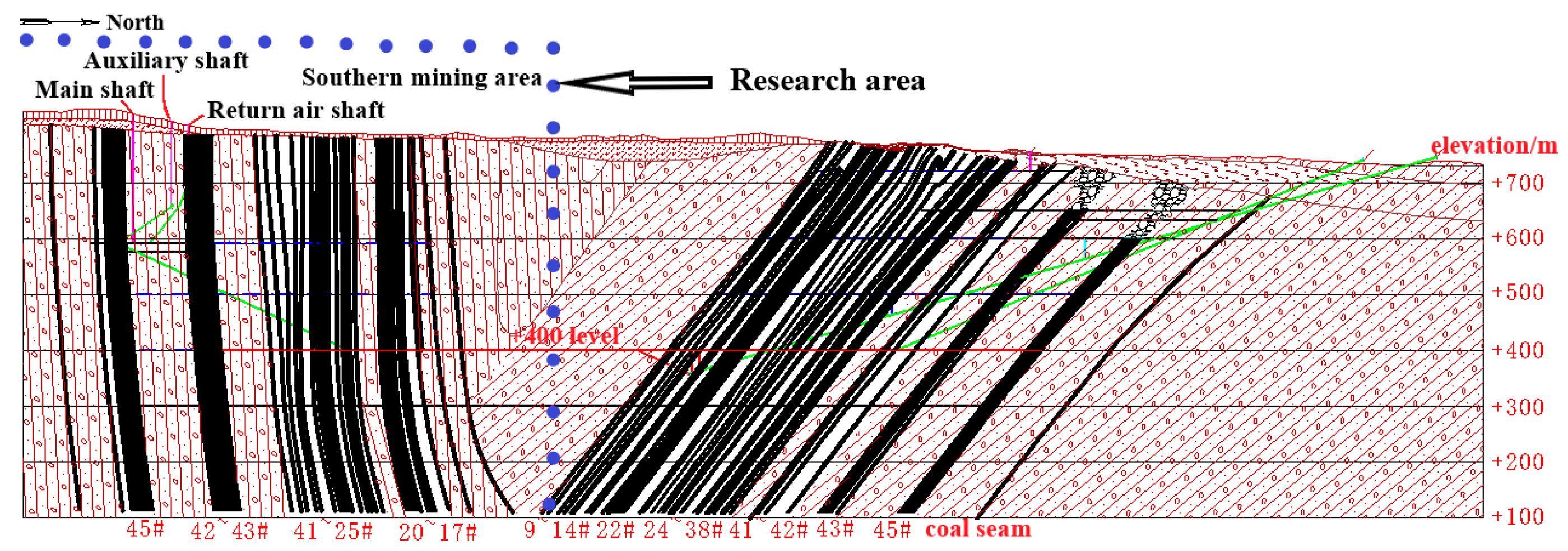
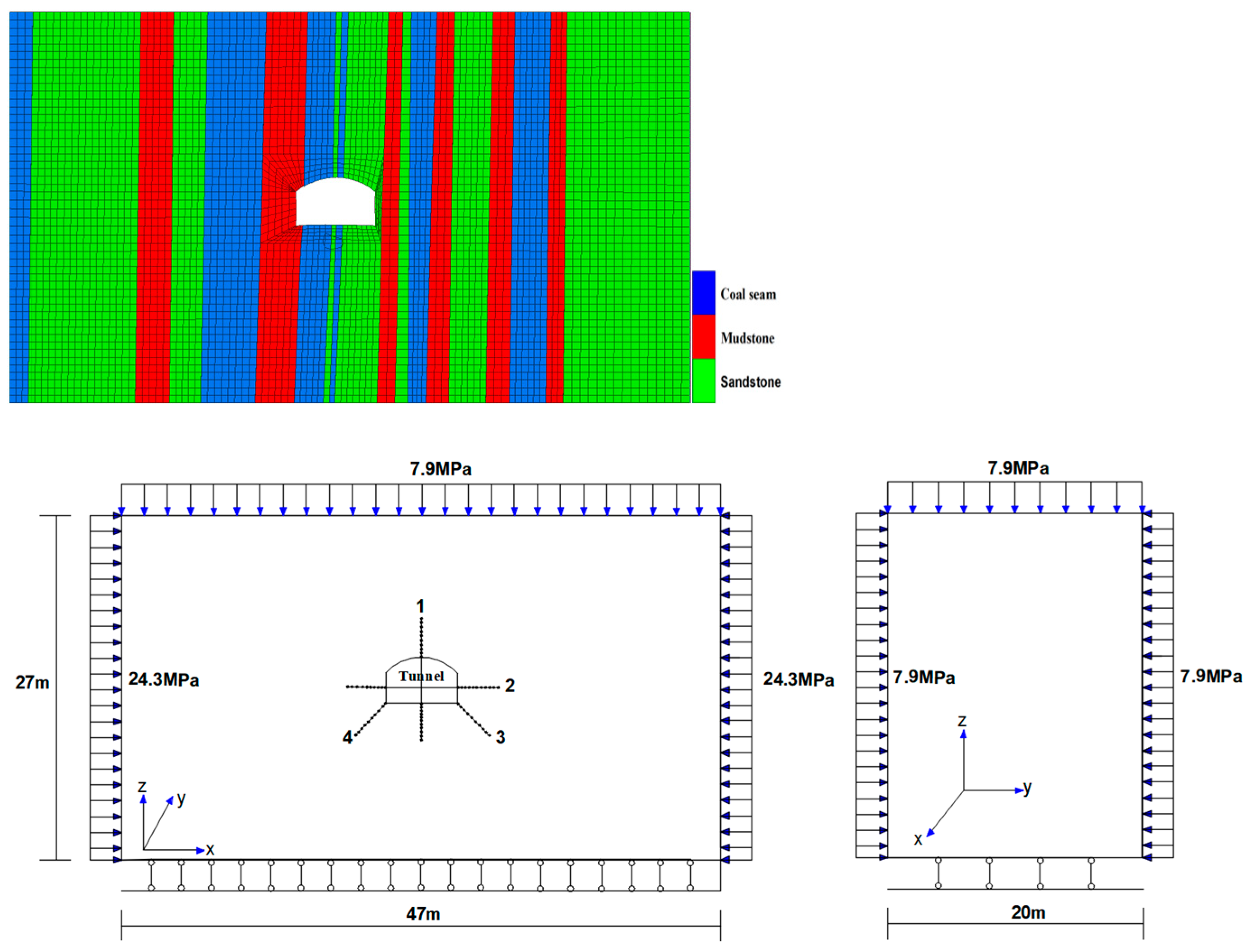
The Wudong Coal Mine is located in Midong District, Urumqi City, belonging to Zhunnan Coalfield. The mining area is about 19.94 km2, and the average inclination of the coal seam is 87°. As shown in Figure 1, it is a typical vertical coal seam when the dip inclination is evaluated. The geological structure of B13–14 coal seam is simple, because the coal seam is located in the south wing of Badaowan syncline and is a monoclinal structure tilted to the northeast as a whole. The +400 level B8 centralized transportation roadway (southern section) is driven along the B13–B14 coal seam, with a design length of 786 m. The ground elevation and the underground elevation of the roadway are 800 m and 400 m, respectively. It is apparent in Figure 1 that the distance to the south of the +400 level B2 drainage roadway is 270 m, while the north and upper parts are original rocks without any mining activities.
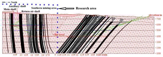
Figure 1.
Profile of Wudong Coal Mine field.
Both the roof and floor of the coal seam are dominated by siltstone, mudstone and carbonaceous mudstone. The lithology of the coal seam roof and floor is listed in Table 1. Bedding and fractures are developed, and argillaceous cementation occurs. Note that there are 1–2 layers of dirt bands in the coal seam. The lithology of the dirt bands is carbonaceous mudstone and carbonaceous shale. The coal seam nearby the dirt bands is broken and easy-to-collapse. Moreover, the surrounding rock of the roadway is easy-to-deform when encountering water.

Table 1.
The lithology of coal seam roof and floor.
The cross-sectional form of the roadway is a straight-wall circular arch, as indicated in Figure 2. The designed excavation width of the roadway is 5.6 m, with a net width of 5.4 m. The excavation height is 3.6 m, the net height of which is 3.5 m. As a result, the excavation cross-sectional area is 18.2 m2, with a net cross-sectional area of 16.6 m2. The combination support techniques with the application of anchor rods, cables, anchor mesh, steel belts, as well as the shotcrete was adopted in maintaining the stability of the surrounding rock.
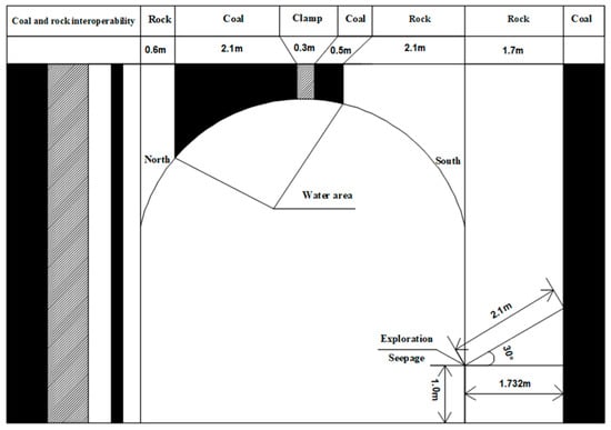
Figure 2.
Cross section of the roadway.
3. Theoretical Analysis
3.1. Distribution Characteristics of Crustal Stress in Wudong Coal Mine
To tackle the serious deformation problem of the B8 roadway in the Wudong Coal Mine, four representative measuring points are allocated in the B8 roadway. The hollow inclusion stress-relief method is used to monitor the original rock stress, which is a kind of stress-relief method. It can determine the magnitude and direction of the three-dimensional stress in the original rock by presetting the measuring probe in a single borehole. The monitoring results showed that: (1) the measured value of vertical principal stress approaches or is slightly less than the weight of the overlying strata. (2) The value of vertical principal stress is 7.43~9.13 MPa, an average of 7.90 MPa. The maximum horizontal principal stress is 23.75~24.85 MPa, an average of 24.3 MPa. The ratio (lateral pressure coefficient) of the maximum horizontal principal stress to the vertical principal stress is 2.72~3.19, which is above 1, suggesting that the area is strongly influenced by tectonic movement. The tectonic stress plays a controlling role in the stress field. In-situ stress is mainly horizontal stress that belongs to the type of tectonic stress field. (3) The difference between the maximum horizontal principal stress and the minimum horizontal principal stress is significant. That is, the influence of horizontal stress on the roof, floor and ribs of the roadway exhibited a clear directionality, and the in-situ stress field in the Wudong Coal Mine is a tectonic stress field dominated by horizontal stress. In particular, the direction of the in-situ stress field has a larger effect on the stability of the roadway. It is thus believed that the size of the stress is the main reason influencing the stability of the roadway, leading to serious deformation of the roadway in the high-stress area.
3.2. Stress Distribution Characteristics of Surrounding Rock in Straight-Wall Circular Arch Roadway
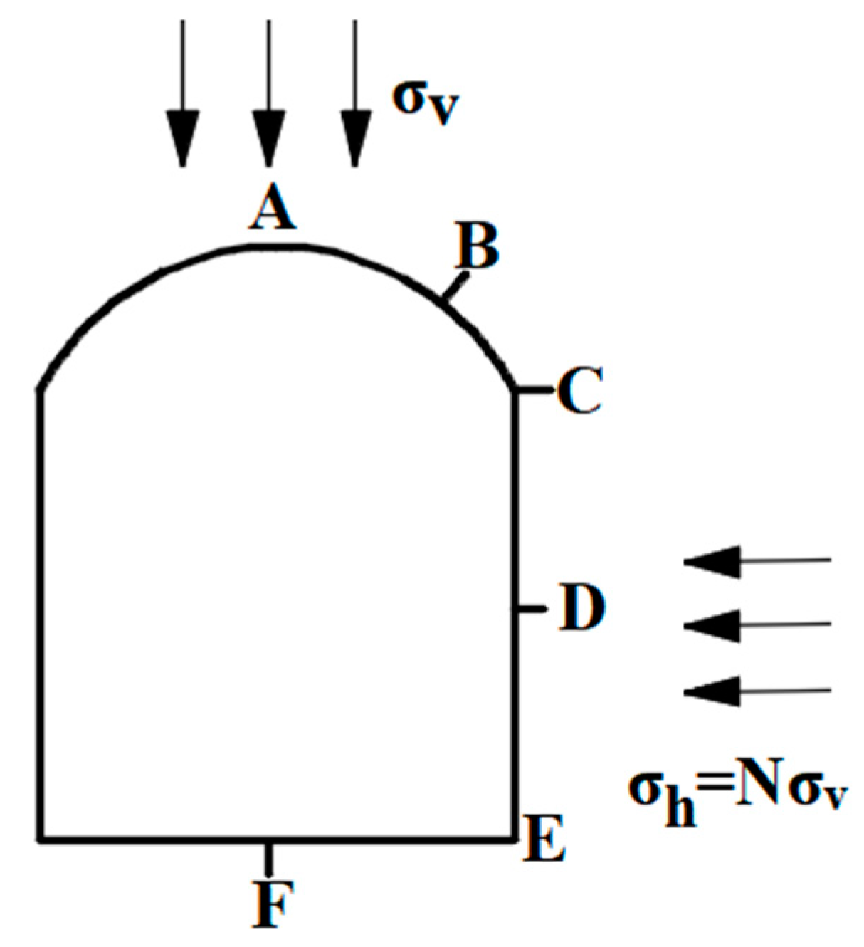
According to the elasticity theory, a stress distribution calculation model for the surrounding rock of a straight-wall circular arch roadway is constructed. As depicted in Figure 3, σh represents the horizontal stress in the rock mass; σv denotes the vertical stress in the rock body; N is the lateral pressure coefficient. Six characteristic points are selected on the roadway cross-apart, namely point A, point B, point C, point D, point E and point F. The values of α and β in the stress concentration coefficients of each feature point in the figure are shown in Table 2 [28]. The tangential stress of each characteristic point is calculated using the following equation [29]:
where α + βN is called the stress concentration coefficient.
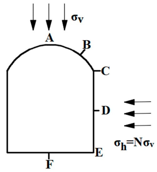
Figure 3.
Cross section of straight-wall circular arch roadway.
Table 2.
The value of α and β in the stress concentration coefficient.
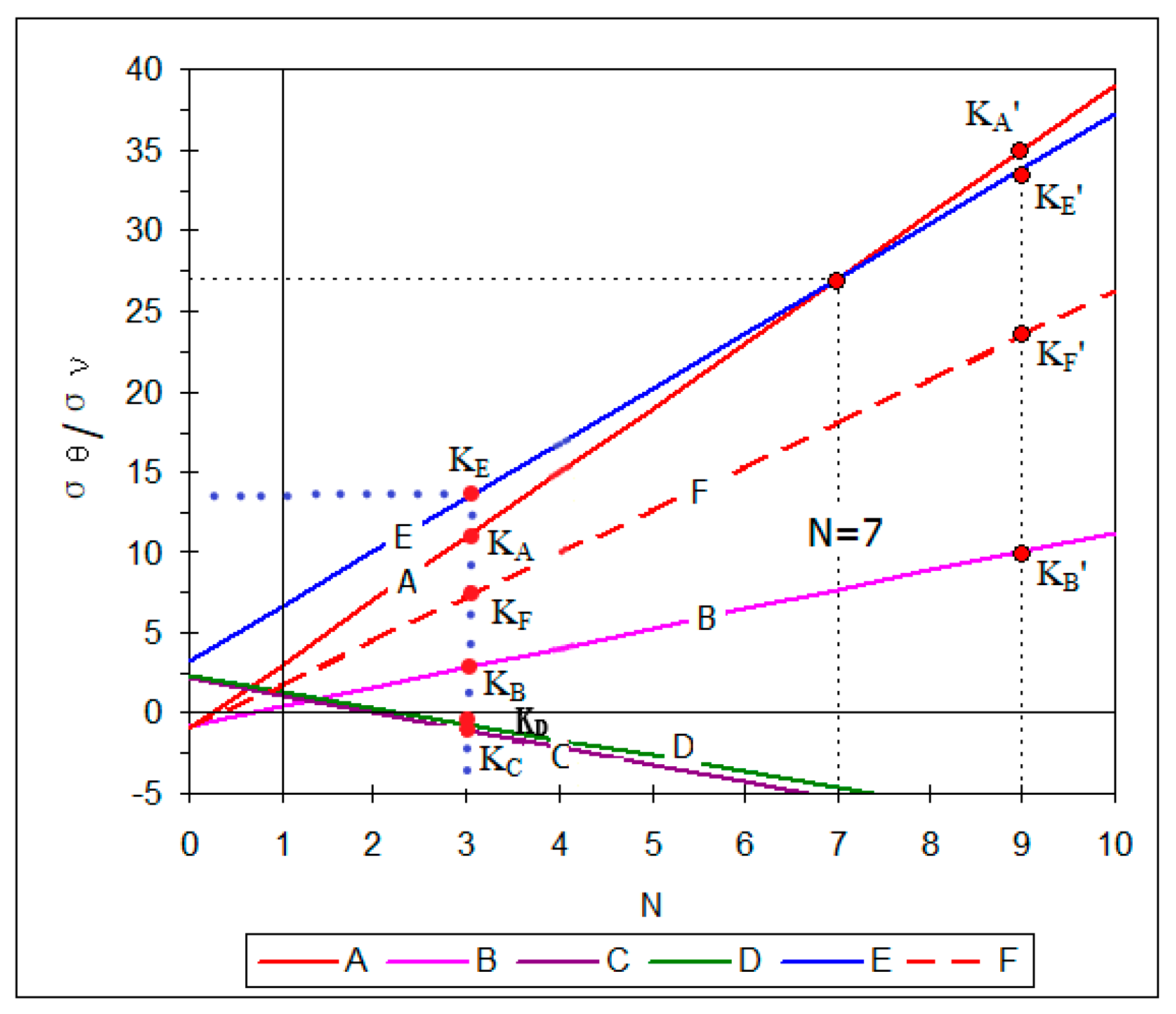
According to the relationship between the stress concentration coefficient around the roadway and the N value, as shown in Figure 4, the measured consequence of in-situ stress in the Wudong Coal Mine is different. It is clear that the compressive stress concentration at points A, B, E and F are different, when the value of the lateral pressure coefficient is 3.08. Among them, the largest stress concentration coefficient of 13.5 corresponds to point E. When the values of points A, F and B are evaluated, there is a subsequent decrease. It is interesting that points C and D show different degrees of tensile stress concentration, among which the stress concentration coefficient at point D is the smallest. It can be deduced that when the transport roadway is excavated, compressive damage occurred at these four points in the roadway envelope. The evidence is that the large stress concentration coefficients occurred at points A, B, E and F, whereas tensile damage was generally observed from these points in the roadway envelope due to the stress concentration coefficients at points C and D being smaller.
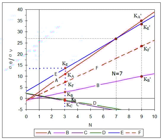
Figure 4.
Relationship between stress concentration coefficient and N value around the roadway.
4. Numerical Simulation
4.1. Construction and Parameter Selection of Numerical Model
As a 3D continuum mechanical analysis software developed by Itasca company, FLAC3D 5.0 was applied in the present research to conduct numerical simulation. It adopts the explicit Lagrange algorithm and mixed-discrete partition technology to solve the dynamic equation, which can achieve simulation. Adjusting the three-dimensional mesh can simulate and study the real shape of the object, and the post-processing function is powerful. It combines Mohr–Coulomb failure criterion and tensile failure criterion to form its Mohr–Coulomb constitutive model from the incremental equation of plastic flow theory [30,31,32].
As per the geological conditions of the Wudong Coal Mine, a FLAC3D numerical model with a size of long × wide × height = 47 m × 20 m × 27 m was established; after cell division, the computational grid is formed associated with 80,000 cells and 89,892 nodes. The vertical load is applied to the rock mass from the roof of the roadway to the surface. The roller boundary is used to limit the horizontal movement on the model sides, and the fixed boundary is used to limit the bottom of the model. The boundary in-situ stress is applied to the roof and two sides of the model. Figure 5 shows the model parameters, and Mohr–Coulomb criteria are applied. The mechanical parameters of the surrounding rock of the roadway are shown in Table 3.
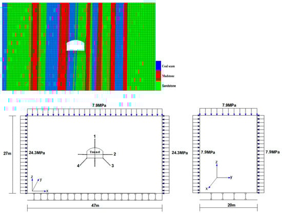
Figure 5.
FLAC3D numerical calculation model and model calculation diagram.
Table 3.
Mechanical parameters of roadway-surrounding rock.
For the sake of grasping the deformation and instability features of the surrounding rock, four measuring lines were set up. As depicted in Figure 5, the first line is set in the center of the roadway roof and floor and the second one is placed at the center of the left and right sides of the roadway. The third measuring line is at the bottom corner of the right side of the roadway, while the fourth line is arranged at the bottom corner of the left rib of the roadway. Because the constant measuring point with an interval of 50 cm was given, there are 12 measuring points arranged on each measuring line.
4.2. Stress Analysis of Roadway-Surrounding Rock
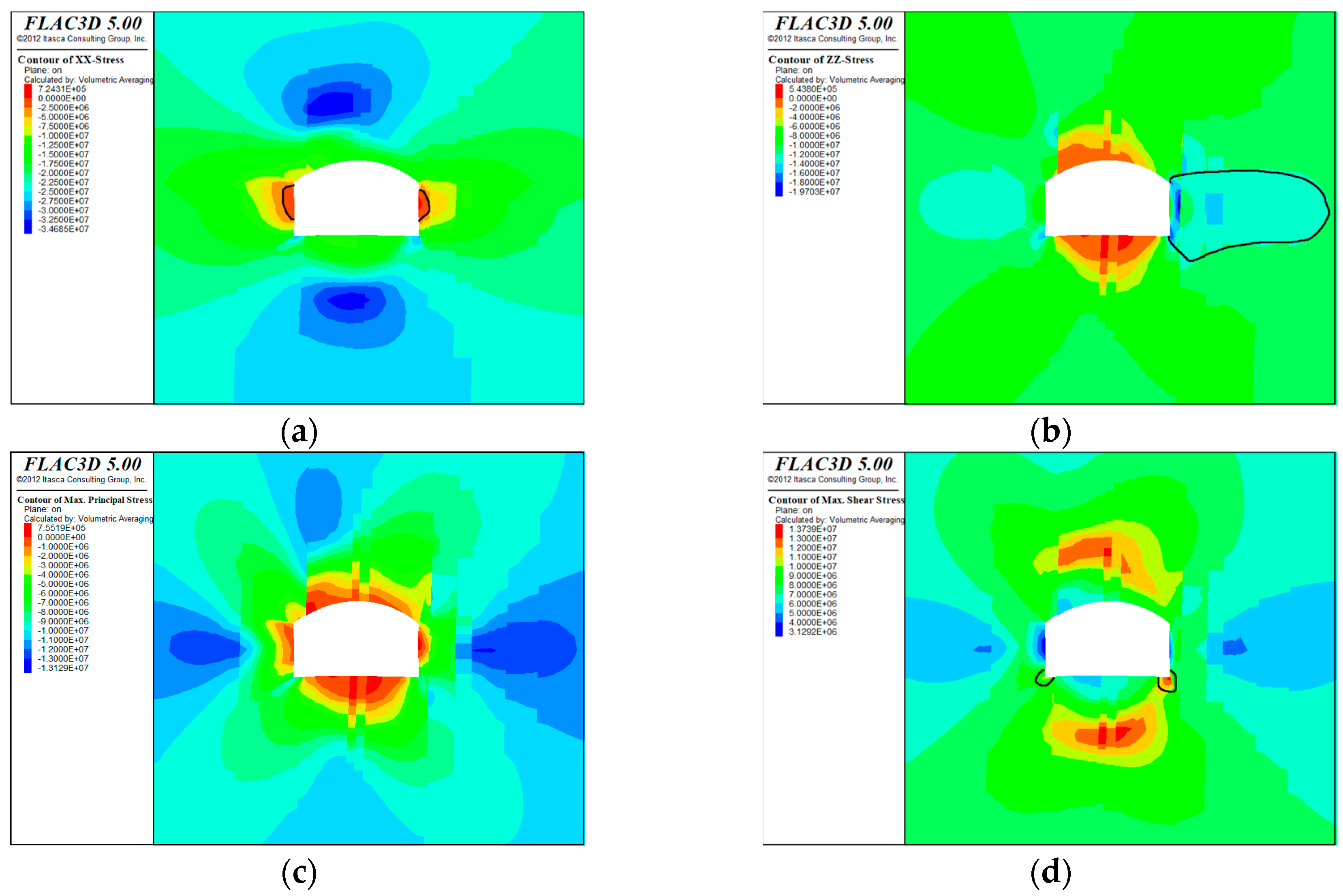
Figure 6 displays that the stress in the surrounding rock shows significant asymmetric distribution after the excavation of the roadway. It is interesting in Figure 6a that the horizontal stress is significantly released on the ribs of the roadway. Herein, the stress contour of the surrounding rock presents a semi-circular distribution. In this case, the high-level stress centralized region occurred at the bottom corner of the left and right ribs of the roadway, with the maximum stress value of 34.6 MPa, and the stress concentration coefficient is 1.4.
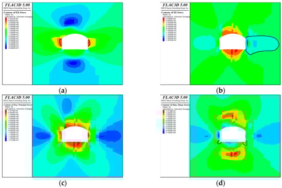
Figure 6.
Stress distribution diagram of roadway surrounding rock. (a) Horizontal stress; (b) Vertical stress; (c) Maximum principal stress; (d) Maximum shear stress.
As shown in Figure 6b, the different rock layers exhibit significant stress discontinuity because of dislocation due to the relatively fractured lithology of the coal rock mass. The vertical stress values that measured from the roof and floor of the roadway are relatively smaller than that of the ribs. Note that the high-stress contour on the right rib extends relatively wide to the deep rock mass. The high-stress centralized region is situated within the rock layer 1m apart from the right rib of the roadway, with a maximum stress value of 19.7 MPa. In this case, the large stress concentration coefficient of 2.49 results in the instability and damage of surrounding rock.
The roadway is featured with a significant asymmetry, as the maximum principal stress distributed around the surrounding rock is evaluated. The peak values of the maximum principal stress in both ribs are located within the rock layers at a distance of 4 m from the left and 5 m from the right sides, respectively. The influence range is large, with a stress value of 13.1 MPa, mainly dominated by compressive stress.
It is in Figure 6d that the distribution of shear stress in the surrounding rock exhibits obvious stress discontinuity, mainly attributed to the occurrence features of coal and rock. The maximum shear stress areas mainly dominated in tension are observed from the bottom corners of the ribs, with a maximum shear stress value of 13.7 MPa.
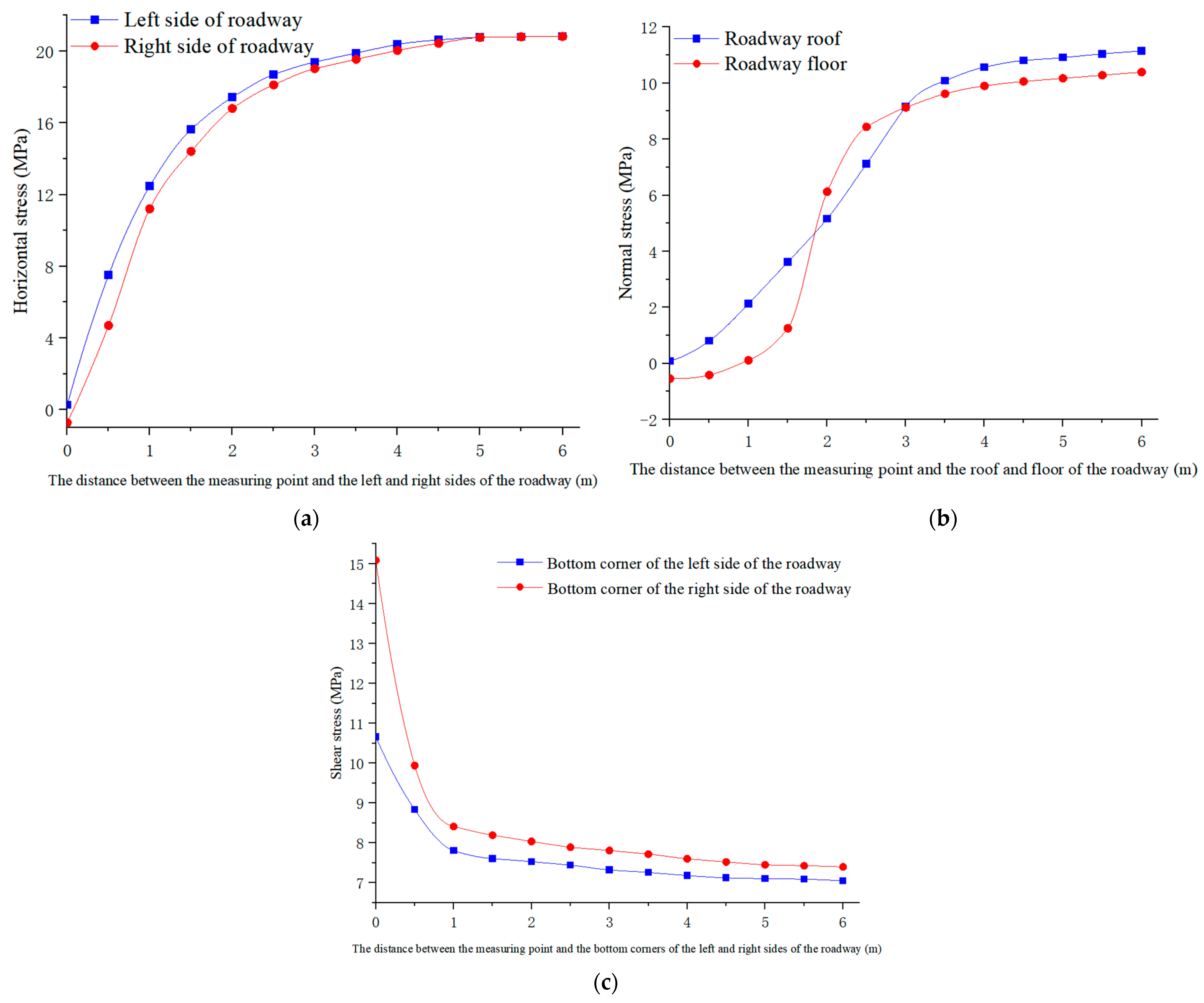
The stress change curve of the surrounding rock of the roadway is seen in Figure 7.
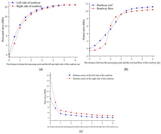
Figure 7.
Stress variation curve of roadway surrounding rock. (a) The left and right sides of the roadway; (b) The roof and floor of the roadway; (c) The bottom corner of two sides of the roadway.
As seen in Figure 7a, there is a significant tensile stress at the right rib of 0.7 MPa. However, the significant compressive stress on the left rib is small. Particularly, the horizontal compressive stress on both ribs gradually increases, with the increasing depth of the surrounding rock. This situation will last and become stable at a depth of 6 m.
It is apparent in Figure 7b that the significant tensile stress was observed at the floor of the roadway, with a stress value of 0.54 MPa. However, there is a significant compressive stress at the surrounding rock of the roof, with a smaller stress value. As the surrounding rock’s depth increases, the vertical compressive stress on the roof and floor gradually increases. Even though the growth trend of the stress on the roof is greater than that on the floor, it will finally be stable at a distance of 5.5 m from the roof and floor.
As shown in Figure 7c, an obvious shear stress occurred at the bottom corners of the ribs. The shear stress value at the right corner is greater than that at the left corner, with a shear stress value of 15.1 MPa. With the increase in the surrounding rock’s depth, the shear stress at the bottom corners of the roadway ribs gradually decreases and gradually stabilizes at a distance of 4 m from the bottom corners of the left and right sides.
4.3. Analysis of Displacement of Surrounding Rock in Roadways
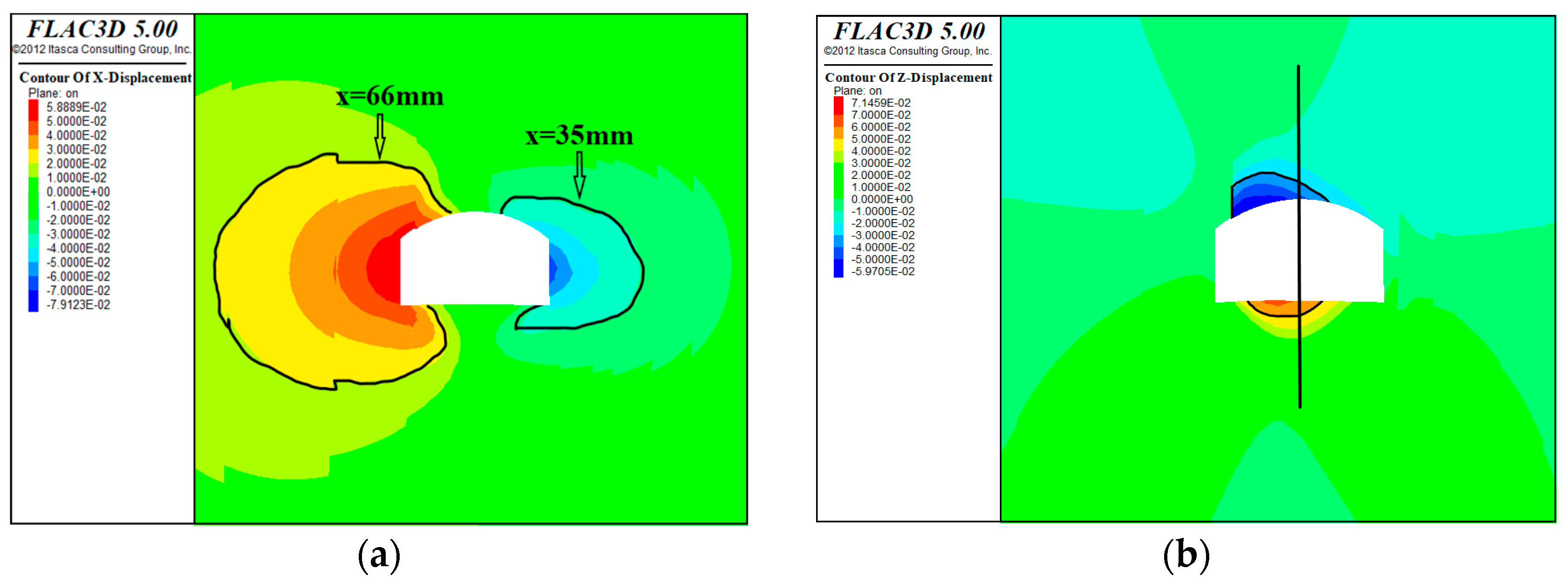
Figure 8 reveals the distribution of displacement in the surrounding rock of the roadway.
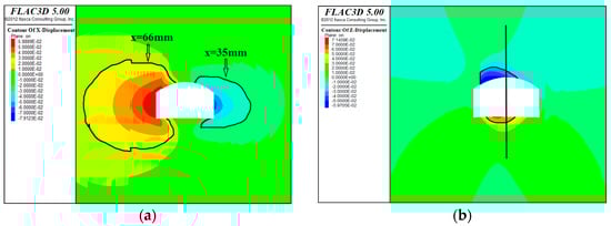
Figure 8.
Vertical displacement distribution graph of the roadway surrounding rock. (a) Horizontal displacement; (b) Vertical displacement.
The deformation characteristics of the roadway, as depicted in Figure 8a, are featured with roof sinking and floor bulging, which is of obvious asymmetry. The overall deformation range of the left rib of the roadway is over that of the right rib. However, the displacement is smaller with a displacement of 58 mm, whereas the maximum displacement of the right rib reaches 79 mm. Figure 8b displays the main deformation feature of the roadway floor heave, which has a wide range of influence. The displacement of the bulge achieves its maximum value of 71.4 mm in the middle left of the roadway floor. Differently, the subsidence of the roof is relatively small, reaching 59.7 mm at the middle left of the roof.
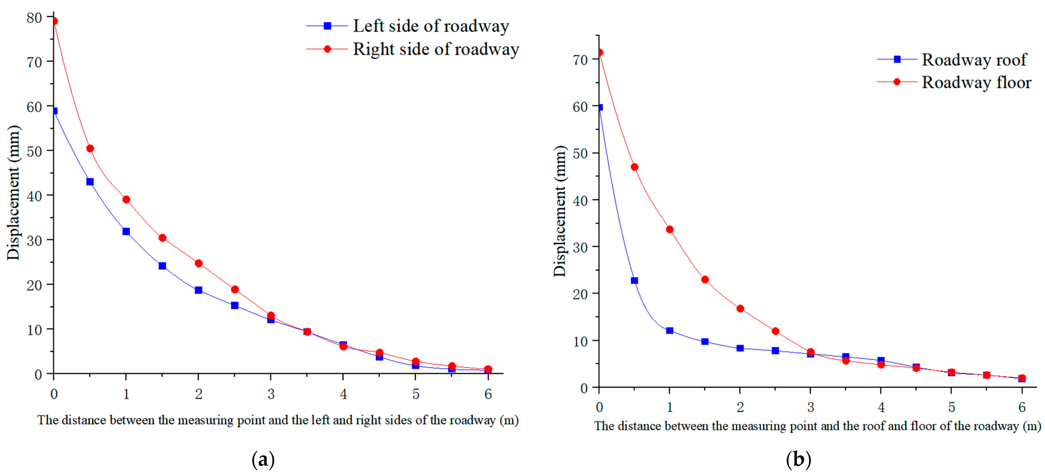
Figure 9 gives the distribution of the displacement curve of the surrounding rock of the roadway. It can be clearly seen from Figure 9a that the overall horizontal displacement of the right rib of the roadway is more than that of the left rib. Moreover, the horizontal displacement of the right rib reaches 79 mm. As the depth of the surrounding rock increases, the horizontal displacement gradually decreases. The vertical displacement at the middle left of the roadway floor exhibits the maximum values, with a displacement of 71 mm. It was found from Figure 9b that the displacement change in the roadway roof is comparatively small, with a displacement of 59 mm. That is, the deformation of the surrounding rock on the right rib of the roadway is significantly more than that of the floor, followed by the roof. The deformation of the left rib of the roadway is the smallest. Meanwhile, the deformation of the roadway-surrounding rock shows a significant asymmetric distribution.
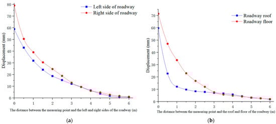
Figure 9.
Displacement curve of the two sides and the roof and floor of the roadway. (a) The left and right sides of the roadway; (b) The roof and floor of the roadway.
4.4. Distribution Characteristics of Plastic Zone
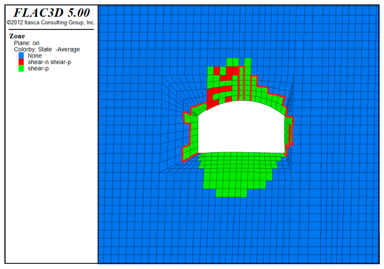
The distribution of plastic zones is shown in Figure 10, in which extensive plastic zones appeared in the surrounding rock due to their shear failure once the roadway was excavated. The plastic zones are mainly distributed in the weak rock mass of the interlayer structure of the roadway and also exhibit asymmetric characteristics. Among them, the roadway roof depth reached 2.8 m, whereas the failure depth of the floor reached 2.7 m. It can also be observed that the failure depth of the left rib and right rib reached 0.5 m and 0.7 m.
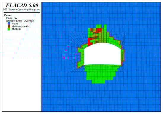
Figure 10.
Characteristics of the plastic zone of the roadway.
5. Research Result
5.1. Field Measurement
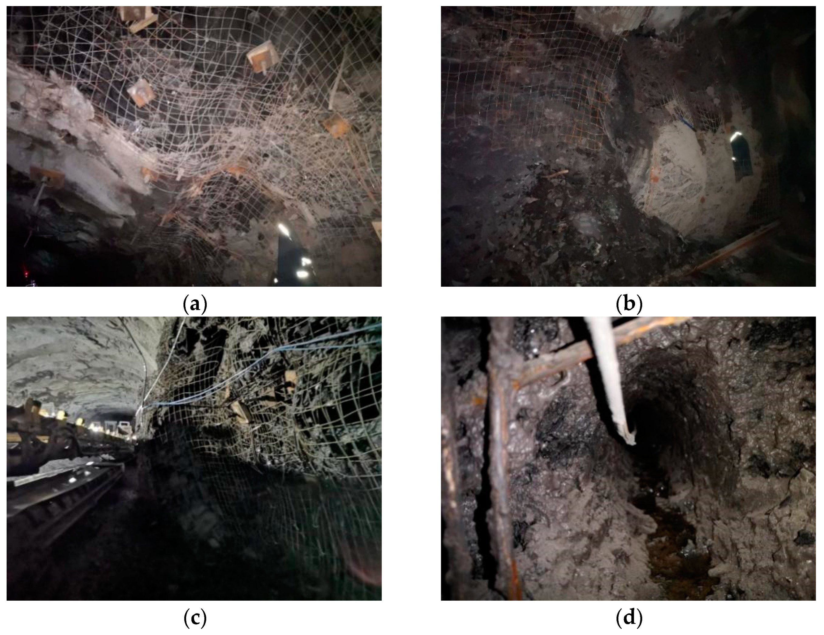
The roof of the transportation roadway tends to stabilize after sinking by 40–60 mm when the excavation process was stopped. The floor heave is 65–80 mm, associated with an overall deformation of 50–90 mm on both ribs of the roadway. Affected by the deformation, the right rib of the roadway was split, and a pressure relief groove was arranged on the floor. In this case, the right rib of the roadway continued to deform, as shown in Figure 11. This mentioned observation agrees well with those obtained by numerical simulation, indicating the accuracy of the numerical simulation. When the on-site measurement results were further evaluated, the deformation amount of the right rib of the roadway was about 85 mm, while the value of that of the left rib was about 50 mm. Correspondingly, the floor heave and roof subsidence are about 75 mm and 66 mm, when the water flowed out at multiple drilling points in the roadway.

Figure 11.
Roof, left and right sides of the roadway and drilling situation of B8 roadway. (a) The roof of the left side of the roadway; (b) The left side of the roadway bulging; (c) The right side of the roadway bulging; (d) Drilling situation.
5.2. Analysis of Instability Characteristics of Surrounding Rock in Roadway
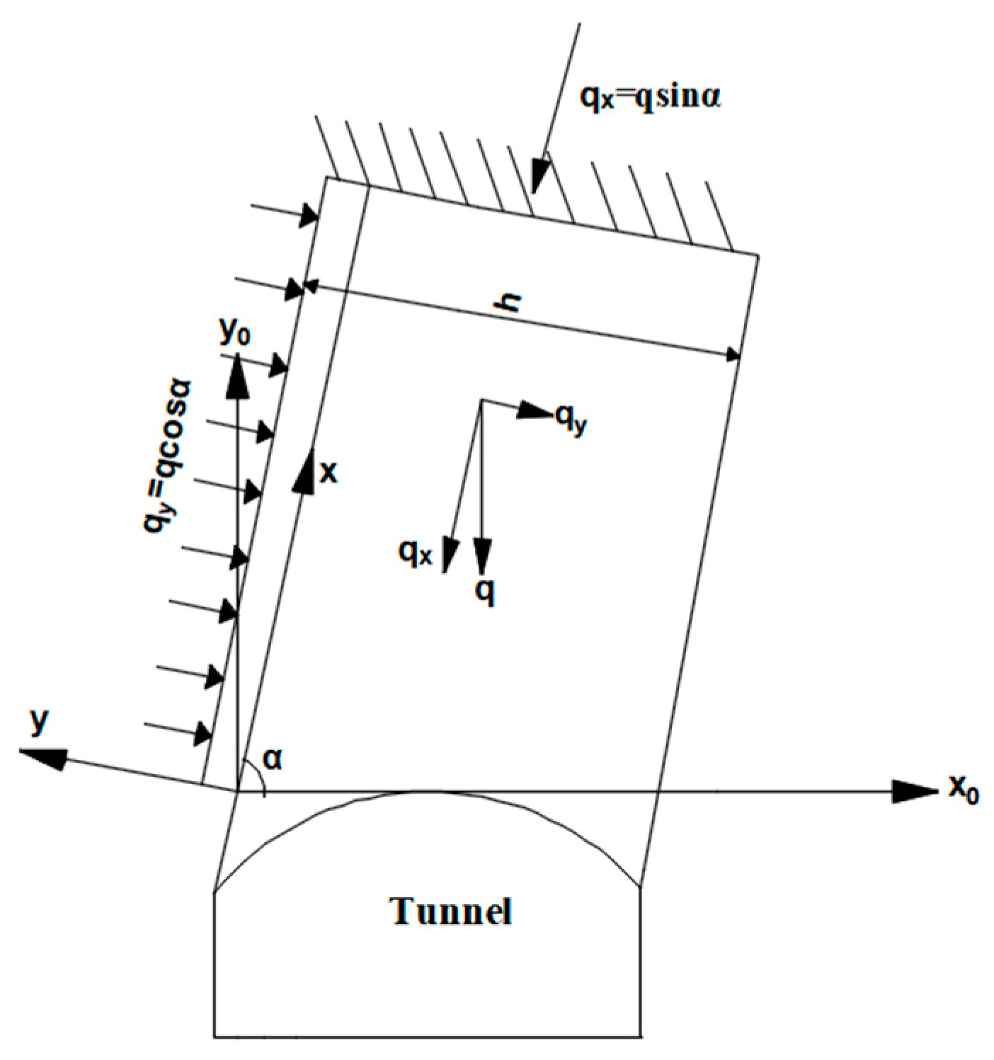
According to the theory of elastic–plastic rock [33], a mechanical model of the roadway roof is built. The original rock stress is located is the x0y0 coordinate system, and the roadway roof is considered as a fixed beam supported by the rock mass at both ends, as indicated in Figure 12. The h denotes the thickness of the rock beam, and the load on the overlying rock layer is =; the inclination angle of the top plate is α. For the convenience of analysis, the overlying rock load on the roof is decomposed into = and =. For the roadway roof, mainly exerts axial compression. According to material mechanics, when the settlement of the roadway roof is small, has little contribution to the bending moment of the roof, and is key to the stability of the roof. In view of this, the following analysis of the roof mechanics model still projects the force in the direction of the vertical roof and the direction of the roof inclination and takes the load of the vertical roof as the research object.
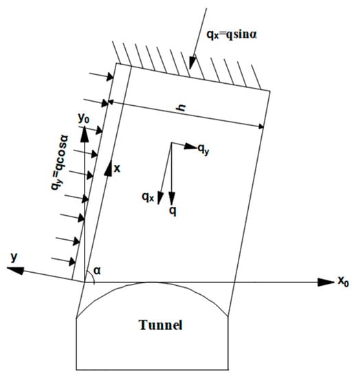
Figure 12.
Mechanical model of roadway roof.
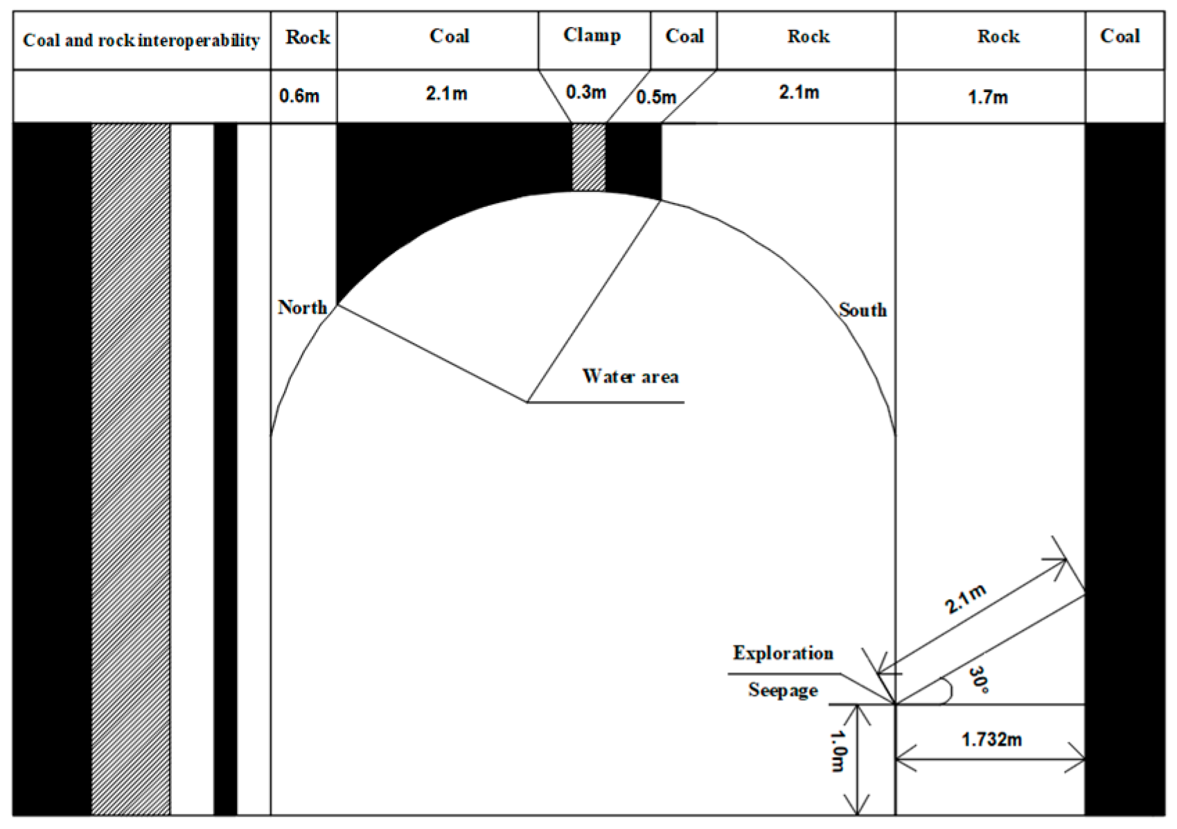
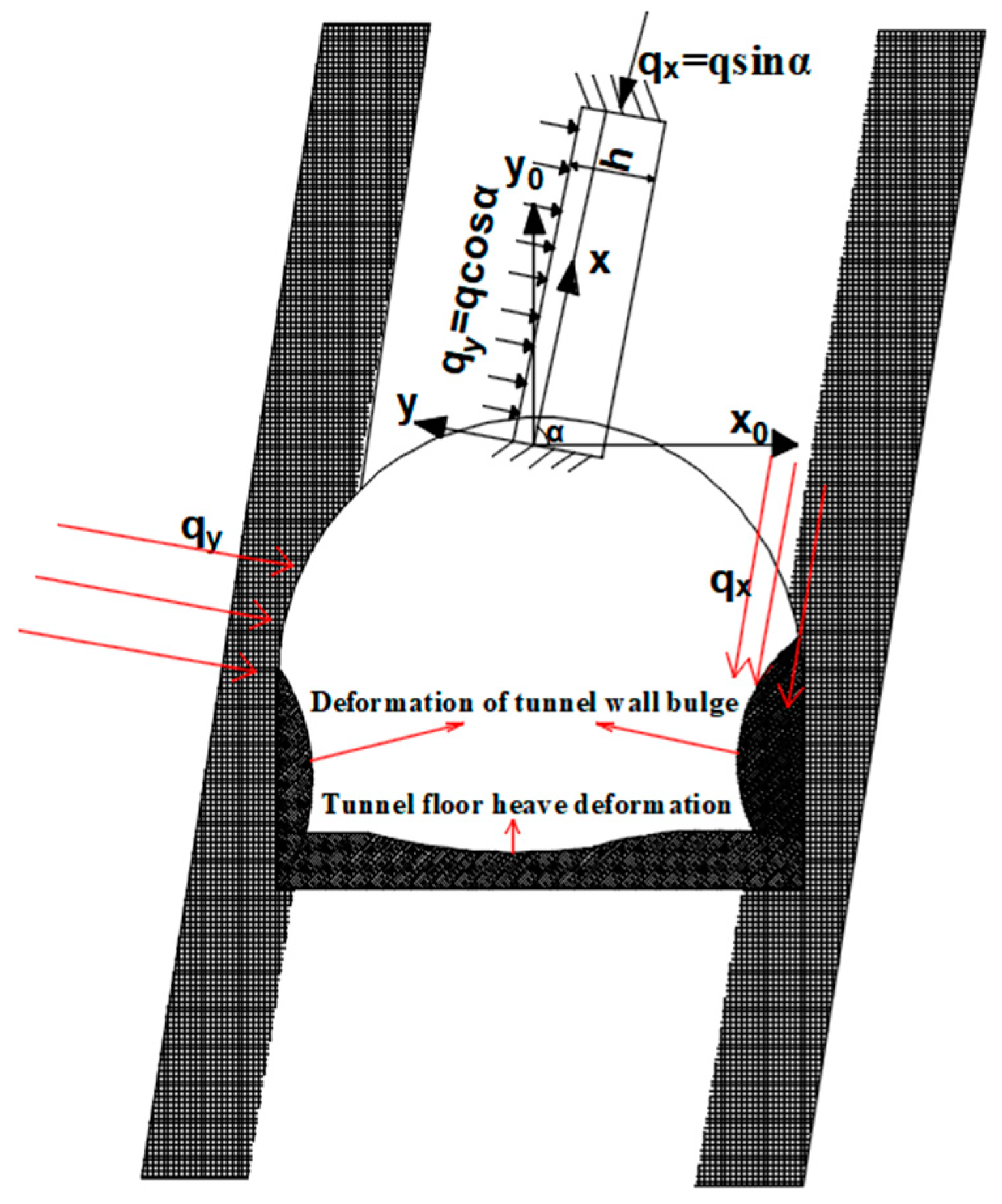
Due to the large dip angle of the coal rock layer, the gravity of the rock can be segmented into a component perpendicular to the bedding plane and a component along the bedding plane, as shown in Figure 13.
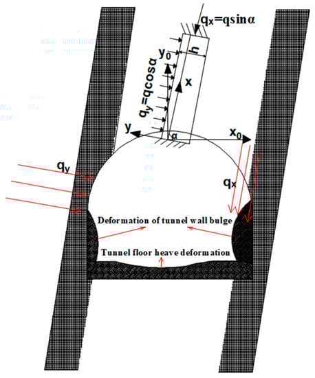
Figure 13.
Instability characteristics of surrounding rock in nearly vertical coal–rock-interbedded roadway.
- (1)
- From the left rib of the roadway, it acts on the left rib along the vertical bedding plane direction. When it is from the upper right rib of the roadway, it acts on the right rib along the bedding plane direction. Because the rock layer has a large inclination angle, the force of gravity along the bedding direction of the coal rock layer increases. Because of that, the coal seam and its adjacent parts of the rock layer are relatively soft; the structural planes are relatively developed. Consequently, the soft coal seam and rock mass are prone to severe dislocation deformation, resulting in the rock mass sliding along the bedding plane and the subsidence of the roadway roof rock layer. Owing to the lithology of the roadway floor, the strength of the coal–rock interbedding is relatively low, and serious floor heave under the effect of tectonic stress will consequently occur;
- (2)
- When the thickness of the coal rock layer is small, the coal rock layer is similar to a longitudinal bending instability structure where the upper and lower ends are constrained and vertically compressed. The stress on the left and right sides and the roof are different, so the displacement of the roof on one side of the roadway is large, which is easier for bulging deformation;
In summary, the asymmetric distribution of stress in the surrounding rock of the nearly vertical coal–rock interlayer roadway causes deformation and failure of the roadway-surrounding rock. There is obvious asymmetry or imbalance within the same cross-section because of the large deformation of the surrounding rock near the roadway and floor. The possible reason for this phenomenon is that the surrounding rock is sustained to significant asymmetric loads. Moreover, the poor lithology of the surrounding rock makes shear dislocation prone to occur between interbedded rock layers.
5.3. Deformation and Instability Mechanism of Roadway-Surrounding Rock
According to the analysis of the damage of the near-vertical coal–rock-interbedded roadway [34,35], it can be concluded that the mechanisms causing the deformation and damage of the near-vertical coal–rock-interbedded roadway are mainly manifested in:
- (1)
- The asymmetric mechanism of the rock mass structure: the nearly vertical coal–rock-interbedded roadway is affected by the occurrence characteristics of coal and rock layers; the rock structure of both ribs exhibited an obvious asymmetry, leading to the asymmetry of stress distribution in the surrounding rock. The roof and floor of the surrounding rock of the nearly vertical coal–rock-interbedded roadway are coexisting with different media of coal and rock. Under the compression of the rock layer, the coal body is broken, which easily causes the weak surface sliding between the coal and rock masses because of the low strength of the coal seam, leading to the subsidence of the roadway roof and the bulging of the rib;
- (2)
- The sliding deformation mechanism at the rock mass level: the normal load on the nearly vertical coal layer is comparatively small. It is because the force of gravity along the coal layer direction increases, resulting in shear slip deformation of the weak or potential shear surface between the rock layers at the bottom corners of the two ribs of the roadway. When the angle between the roadway section and the inclination direction of the rock layer is small, the lateral constraint caused by the inclination direction of the rock layer increases the vertical stress between the rock layers, resulting in small shear slip deformation. However, for these parts where the roadway section and the inclination direction of the rock layer are at an obtuse angle, the lateral constraint of the rock layer will be small. In this situation, large shear slip deformation is easily caused, leading to an augment in the overhanging area of the roadway roof. The unrestrained range of the roadway floor increases, and it produces bending deformation under the effect of structural stress, causing the roadway roof to sink and the floor to heave greatly.
6. Conclusions
- (1)
- The average maximum horizontal principal stress of the Wudong Coal Mine is 24.3 MPa, which is about 3.08 times the vertical principal stress. When the transport roadway at +400 level was excavated, each feature point was damaged by a different nature of force attributed to the different stress concentration coefficient;
- (2)
- The stress load of the surrounding rock of the near-vertical coal–rock-interbedded roadway presents an asymmetric distribution featured with an obvious stress discontinuity;
- (3)
- The surrounding rock of the transport roadway has a large range of plastic zone, and the shear failure is the main failure. The unique deformation features of the surrounding rock make it difficult to control the deformation of the surrounding rock;
- (4)
- The normal load applied on the nearly vertical coal–rock layer surface is relatively small, thus the force of gravity along the coal–rock layer direction increases, while the suspended area of the roadway roof and the unrestrained range of the floor increase due to the shear sliding failure;
- (5)
- The flexural deformation is produced under the effect of tectonic stress, which makes the deformation and damage of the near-vertical coal–rock-interbedded roadway present the destabilization mechanism of “ribs heave, roof subsidence and floor heave”;
- (6)
- Mastering the deformation mechanism of the surrounding rock of the near-vertical coal–rock-interbedded roadway can provide a guiding role for deformation control of the near-vertical coal–rock-interbedded roadway.
Author Contributions
Conceptualization, Y.Y. and H.W.; methodology, H.W. and Y.Y.; validation, Y.Y. and H.L.; investigation, Y.Y. and H.W.; data curation, Y.Y.; writing—original draft preparation, Y.Y., H.W. and G.L.; writing—review and editing, Y.Y., H.W. and H.L. All authors have read and agreed to the published version of the manuscript.
Funding
This research was funded by the National Natural Science Foundation of China, (No. 51964043); Natural Science Foundation of Xinjiang Uyghur Autonomous Region (No. 2022D01E31); Xinjiang Uygur Autonomous Region “Tianshan Talent Training” Program (No. 2022TSYCCX0037); Xinjiang Uygur Autonomous Region Special Program for Key R&D Tasks (Nos. 2022B01034 and 2022B01051); the National Natural Science Foundation of China Regional Program (No. 51964043); the Key Project of the Joint Funds of the National Natural Science Foundation (No. U1903209).
Data Availability Statement
The research data applied to support the findings of this study are currently under embargo while the research findings are commercialized. Requests for data, 12 months after publication of this article, will be considered by the corresponding author.
Acknowledgments
We would like to acknowledge Chengfang Shan Senior Engineer, Yafeng Li Assistant engineer, Fajun Yang Intermediate engineer, Peng Zhu Engineer, Haitong Kang Senior Engineer and Guoliang Xie Senior Engineer for their geological and mine information and support.
Conflicts of Interest
The authors declare no conflict of interest.
References
- Zhang, D.S.; Liu, H.L.; Fan, G.W. Connotation and prospection on scientific mining of large Xinjiang coal base. J. Min. Saf. Eng. 2015, 32, 1–6. [Google Scholar]
- Wu, Y.P.; Xie, P.S.; Ren, S.G. Analysis of asymmetric structure around coal face of steeply dipping seam mining. J. China Coal Soc. 2010, 35, 182–184. [Google Scholar]
- Das, A.J.; Mandal, P.K. Evaluation of stability of underground workings for exploitation of an inclined coal seam by the ubiquitous joint model. Int. J. Rock Mech. Min. Sci. 2017, 93, 101–114. [Google Scholar] [CrossRef]
- Dai, H.Y.; Yi, S.H.; Ju, W.J. The movement law of rock strata in horizontal slice fully mechanized top-caving mining of steep-inclined coal seams. Chin. J. Eng. 2006, 5, 409–412. [Google Scholar]
- Jia, P.; Tang, C.A. Numerical study on failure mechanism of roadway in jointed rock mass. Tunn. Undergr. Space Technol. 2008, 23, 500–507. [Google Scholar] [CrossRef]
- Li, S.G.; Cheng, X.Y. Research on technology of anchor cable supporting and grouting reinforcement for dynamic pressurized roadway with crushed surrounding rock. Int. J. Coal Sci. Technol. 2016, 44, 67–72. [Google Scholar]
- Zhang, G.Y.; Zhao, Y.L.; Shang, Y.Q. Study on key control technology of floor heave in soft rock roadway. Int. J. Coal Sci. Technol. 2019, 47, 63–67. [Google Scholar]
- Wang, S.R.; Wang, J.A.; Dai, Y. Discrete element analysis of the movement law and failure mechanism of top coal in fully mechanized caving mining of steep thick coal seams. Chin. J. Eng. 2005, 1, 5–8. [Google Scholar]
- Tu, H.S.; Huang, C.W.; Liu, S.Y. Stability control mechanism of roadway in steeply inclined coal seam. J. Coal. Technol. 2020, 39, 12–16. [Google Scholar]
- Ma, Z.Q.; Jiang, Y.D.; Yang, Y.M. Deformation characteristics and control technology of roadways in soft steeply inclined coal seam. J. Min. Safe. Eng. 2016, 33, 253–259. [Google Scholar]
- Shi, P.W.; Gao, Z.N. The failure laws of surrounding rocks and over lying bed in the steep special thickness seam mining. J. China Coal Soc. 2003, 28, 13–16. [Google Scholar]
- Lai, X.P.; Yang, Y.R.; Wang, N.B. Comprehensive analysis to temporal-spatial variation of dynamic instability of steeply inclined coal-rock mass. Chin. J. Rock Mech. Eng. 2018, 37, 583–592. [Google Scholar]
- Sun, Y.D.; Yang, Y.; Sun, B.Y. Sensitivity analysis of roadway surrounding rock deformation factors under dynamic disturbance. Int. J. Coal Sci. Technol. 2020, 48, 57–62. [Google Scholar]
- Huang, Q.H.; Dong, B.L.; Chen, G.H. Failure mechanism of entry in steep soft seam and bolting design. J. Min. Saf. Eng. 2006, 23, 333–336. [Google Scholar]
- Bai, J.B.; Hou, C.J. On bolting support of roadway in extremely soft seam of coal mine with complex roof. Chin. J. Rock Mech. Eng. 2001, 20, 54–57. [Google Scholar]
- Wang, N.B.; Zhang, N.; Cui, F. Characteristics of stope migration and roadway surrounding rock fracture for fully-mechanized top-coal caving face in steeply dipping and extra-thick coal seam. J. China Coal Soc. 2013, 38, 1312–1318. [Google Scholar]
- Huang, D. The Stability Analyses of the Laneway Roof in Soft and Hard Interbedded Rocks. Master’s Thesis, Taiyuan University of Technology, Taiyuan, China, 2004. [Google Scholar]
- Zhang, N.; Li, G.C.; Kan, K.G. Influence of soft interlayer location in coal roof on stability of roadway bolting structure. Rock Soil Mech. 2011, 32, 198–203. [Google Scholar]
- Li, G.C.; Zhang, N.; Wang, C. Optimizing the section shape of roadways in high stress ground by numerical simulation. J. China Univ. Min. Technol. 2010, 39, 25–31. [Google Scholar] [CrossRef]
- Xue, Y.D.; Kang, T.H. Study on the strata and fracture features of surrounding rocks and bolting effect in actual mining roadways. J. China Coal Soc. 2000, 25, 97–101. [Google Scholar]
- Bhasin, R.; Barton, N. Engineering geological characterization of low strength anisotropic rocks in the Himalayan region for assessment of tunnel support. J. Eng. Geolog. 1995, 40, 169–193. [Google Scholar] [CrossRef]
- Symanovych, H.; Salieiev, I. Substantiating the optimization solutions for the mine working fastening system interaction with the enclosing rock mass. J. Min. Miner. Depos. 2022, 16, 54–60. [Google Scholar] [CrossRef]
- Matayev, A.; Abdiev, A. Research into technology of fastening the mine workings in the conditions of unstable masses. J. Min. Miner. Depos. 2021, 15, 78–86. [Google Scholar] [CrossRef]
- Sharan, S.K. Elastic-brittle-plastic analysis of circular openings in Hoek-Brown media. J. Int. J. Rock Mech. Min. Sci. 2003, 40, 817–824. [Google Scholar] [CrossRef]
- Zareifard, M.R.; Fahimifar, A. Analytical solutions for the stresses and deformations of deep tunnels in an elastic-brittle-plastic rock mass considering the damaged zone. Tunn. Undergr. Space Technol. 2016, 58, 186–196. [Google Scholar] [CrossRef]
- Alejano, L.R.; Rodriguez-Dono, A. Ground reaction curves for tunnels excavated in different quality rock masses showing several types of post-failure behavior. Tunn. Undergr. Space Technol. 2009, 24, 689–705. [Google Scholar] [CrossRef]
- Serrano, A.; Olalla, C. Convergence of circular tunnels in elastoplastic rock masses with non-linear failure criteria and non-associated flow laws. J. Int. J. Rock Mech. Min. Sci. 2011, 48, 878–887. [Google Scholar] [CrossRef]
- Zhang, Z.Y. Principle of Engineering Geology Analysis; M. Geological Publishing House: Beijing, China, 1981. [Google Scholar]
- Ding, X.L.; Zhang, Y.T.; Huang, S.L. Large deformation mechanism of surrounding rock masses of roadways, prediction method of squezzing large deformation and its application. Chin. J. Rock Mech. Eng. 2023, 42, 521–544. [Google Scholar]
- Gao, M.L. Analysis of Mechanical Properties and FLAC3D Numerical Simulation on Single Supporting Point of Double Pile—Anchor Supporting System. Master’s Thesis, China University of Geosciences Beijing, Beijing, China, 2012. [Google Scholar]
- Jing, Z. Stress Distribution Characteristics and Coal and Rock Rupture Law of Different Dip Seams under True Triaxial Mining Conditions. Master’s Thesis, Chongqing University, Chongqing, China, 2019. [Google Scholar]
- Mahmoudi, M.; Rajabi, A.M. A numerical simulation using FLAC3D to analyze the impact of concealed karstic caves on the behavior of adjacent tunnels. Nat. Hazards 2023, 117, 555–577. [Google Scholar] [CrossRef]
- Fu, J.X.; Song, W.D.; Du, J.H. Study of stope roof mechanism model and wall rock disturbance law of steeply-inclined thin orebody mining using medium-deep hole. J. Rock Mech. Eng. 2014, 33, 3277–3283. [Google Scholar]
- Zhang, Y.T. Research on Characteristics of Deformation-Failure of Surrounding Rock and Supporting Technology of Roadway in Steep Coal Seam. Master’s Thesis, Xi’an University of Science and Technology, Xi’an, China, 2011. [Google Scholar]
- Qiu, K.K. Research on Surrounding Rock Control of Horizontal Section Fully Mechanized Caving Mining Roadway in Steep Inclined Thick Seam of Yimen Coal Mine. Master’s Thesis, China University of Mining and Technology, Xuzhou, China, 2019. [Google Scholar]
Disclaimer/Publisher’s Note: The statements, opinions and data contained in all publications are solely those of the individual author(s) and contributor(s) and not of MDPI and/or the editor(s). MDPI and/or the editor(s) disclaim responsibility for any injury to people or property resulting from any ideas, methods, instructions or products referred to in the content. |
© 2023 by the authors. Licensee MDPI, Basel, Switzerland. This article is an open access article distributed under the terms and conditions of the Creative Commons Attribution (CC BY) license (https://creativecommons.org/licenses/by/4.0/).