Abstract
In laser powder bed fusion, process-inherited thermal residual stress is developed due to the thermal strain misfit between each layer. Detailed analysis and a prediction of the residual stress are needed because it can induce distortions of the components and, in some serious cases, stress-induced defects such as cracking. In this work, the effects of heat treatment conditions on residual stress in maraging 18Ni-300 steel, fabricated by laser powder bed fusion, were investigated. Cantilever-shaped specimens were used to experimentally analyze residual stress caused by the distortions of the specimens while cutting them from the supporters. The cantilever samples showed complex distortion behavior in the as-built state. They bent downward while cutting them from the supporter when the thickness was relatively thin, and the bending deformation became upward instead of downward with increasing thickness. Interpreting this behavior by finite element simulation showed that the downward bending was due to the compressive stress state at the top layer of the maraging steel. When the cantilever specimens were aging heat treated, the distortions were significantly reduced, implying that the process-inherited residual stress was diminished.
1. Introduction
Maraging 18Ni-300 steel is a type of low-carbon nickel-rich steel alloy that has become increasingly popular in the aerospace, defense, and medical industries due to its unique combination of strength, toughness, and corrosion resistance [1,2,3]. The term ‘maraging’ is derived from a combination of the words “martensitic” and “aging”. The martensitic component of the term refers to the body-centered tetragonal crystal structure of the steel, while the aging component refers to the process by which the material is strengthened in the aging heat treatment. The chemical composition of maraging 18Ni-300 steel includes approximately 18% nickel and 300 ppm carbon, along with trace amounts of other elements such as cobalt, molybdenum, and titanium. This specific composition gives the steel its unique properties, including a high strength-to-weight ratio, excellent toughness, and exceptional resistance to corrosion and wear.
Laser powder bed fusion (LPBF) is a type of additive manufacturing technique that uses a high-powered laser to melt and fuse successive layers of metal powder to form a 3D object [4,5]. In this process, powdered metallic feedstock material is distributed in a powder bed and then each layer is fused by the laser heat source. Three-dimensional metallic components are produced by the repetition of this layering process. This process is highly precise, allowing for the creation of complex geometries and intricate shapes that would be difficult or impossible to produce using traditional manufacturing methods. LPBF is particularly well-suited for the production of maraging 18Ni-300 steel, as the unique combination of the low carbon content and the age-hardenability of the maraging steel allows for the creation of crack-free parts with fine, uniform microstructures that exhibit exceptional strength and durability [6,7,8,9]. In this regard, the relatively low carbon content of the maraging 18Ni-300 steel can effectively prevent the cold cracking caused by the rapid cooling-induced brittle martensite phase formation during LPBF, while the alloy can be easily hardened by the post solution and aging heat treatments.
Conventionally, the heat treatment of the maraging 18Ni-300 steel includes two stages consisting of a short solution treatment above 800 °C, followed by aging at around 500 °C for several hours [10,11]. In the first stage, the solution treatment temperature is chosen to be higher than the austenite transformation temperature of this alloy to ensure the austenitic microstructure of the steel, and this allows the alloying elements to dissolve into the austenitic matrix. In the second stage of aging, the alloying elements precipitate out of solution and form nano-sized intermetallic compounds that strengthen the alloy. In the 18Ni-300 steel, several intermetallic precipitates such as Ni3Ti, Ni3Mo, and Ni3(Mo,Ti) are known to precipitate during the aging treatment with sizes of 8–50 nm [6,12,13]. On the other hand, recent studies have demonstrated that the LPBF-processed maraging 18Ni-300 steel can exhibit exceptional strength and toughness without the need for the solution treatment. Unlike traditional manufacturing methods, which often require solution treatment to dissolve the alloying elements, the microstructure of the maraging steel fabricated by LPBF has a fine structure with near fully dissolved alloying elements due to the sufficiently fast cooling rate of LPBF of up to 106 °C/s. This enables the steel to skip the solution heat treatment. For this reason, the maraging steel produced by LPBF can exhibit excellent tensile properties by only performing an aging heat treatment [9,14,15,16].
When producing metallic components via LPBF, residual stress is a common challenge that can arise during the manufacturing process. Residual stress is an internal stress that remains within a material after it has been subjected to severe deformation or material processing. In the case of LPBF, the residual stress is caused by the localized melting and solidification during the process. As the laser melts the metal powder, it creates localized regions of high temperature that can cause thermal expansion and deformation. As the material solidifies and then cools, the different regions of the part cool at different rates, which can cause large strain misfit and internal stresses to form [17,18,19]. The level and distribution of residual stress within a part can be influenced by a variety of factors, including the laser power, scanning speed, powder layer thickness, and part geometry [18,19]. Residual stress can have a significant impact on the mechanical properties and performance of parts produced using LPBF. High levels of residual stress can cause warping and distortion of the part, leading to dimensional inaccuracies and reduced functionality. In addition, residual stress can also affect the fatigue life of the part, making it more susceptible to cracking and failure [20]. Therefore, understanding and managing the residual stress is critical to ensuring that parts produced using LPBF meet the required performance standards.
There are already a few studies on the residual stress of the 18Ni-300 maraging steel produced by LPBF. For instance, Vrancken et al. [21] have studied the residual stress of the maraging steel produced by LPBF using cantilever distortion tests. Mugwagwa et al. [22] have investigated the effect of LPBF processing parameters on the residuals stress state of maraging steel using cantilever distortion and X-ray diffractions. Recently, Baere et al. [23] have studied the influence of phase transformation in the formation of the residual stress during the LPBF of the maraging steel by a finite element (FE) simulation. However, the effects of aging heat treatment on the residual stress in the maraging 18Ni-300 steel produced by the LPBF have not been investigated yet in the literature, although the aging heat treatment is a necessary procedure in most cases of applications of the maraging steels produced by LPBF.
The aim of this study is to investigate the influence of the post heat treatment conditions on the residual stress in the maraging 18Ni-300 steel produced by LPBF. Cantilever-shaped samples were designed and fabricated by LPBF to evaluate the residual stress. The samples that underwent different heat treatments were used for the tests.
2. Materials and Methods
The maraging steel samples examined in this study were fabricated by using a powder bed-type metal 3D printer (OPM 250L, Sodick Co., Ltd., Yokohama, Japan), equipped with single-mode 500 W ytterbium fiber laser with a wavelength of 1070 nm (YLR-500-WC, IPG Laser GmbH, Burbach, Germany). Gas-atomized maraging 18Ni-300 steel powder (OPM Maraging, OPM Laboratory Co., Ltd., Kyoto, Japan) was used as the feedstock material. The chemical composition of the maraging steel powder used for the LPBF is given in Table 1. The LPBF of the maraging steel was carried out using the LPBF parameters recommended by the manufacturer, e.g., a laser power of 420 W, a laser scanning speed of 1000 mm/s, a hatch spacing of 0.1 mm, a layer thickness of 0.04 mm, and a substrate preheating temperature of 80 °C. According to the manufacturer’s information, these LPBF parameters lead to almost fully dense maraging components with porosities of less than 0.2% and dimensional errors of less than 0.01 mm. A so-called 90° rotate scanning strategy was used. Therefore, the laser scanning lines were 90° tilted between each LPBF layer. More detailed information regarding the maraging steel produced by these LPBF process parameters, including the microstructure and the mechanical properties, can be found in the authors’ previous work [9]. Table 2 summarizes the LPBF process parameters for the 18Ni-300 used in this study.

Table 1.
Chemical composition of maraging 18Ni-300 steel powder.
Table 2.
LPBF process parameters used for 18Ni-300 used in this study.
Cantilever-shaped specimens were designed and produced to quantitatively evaluate the residual stress in the maraging steel produced by the LPBF. Figure 1 shows the schematic design of the cantilever, the deformation measurement method, and the appearance of the LPBF processed maraging steel cantilever specimens used in this study. The cantilever design consists of a 10 mm thick artificial supporter, supporter legs, and a cantilever, as shown in Figure 1a. The supporter and the supporter legs were designed to restrain the vertical deformation of the cantilever during the LPBF and the post heat treatment processes. The cantilevers produced in this study had a horizontal length of 25 mm and had various thicknesses (t) in the range of 0.5–5 mm. Through this design, the residual stress induced by the LPBF process can be isolated in the cantilever and is released when the cantilever is detached from the supporter by cutting the supporter legs, as schematically shown in Figure 1a. With this method, the residual stress in the cantilever can be evaluated by measuring the deformation, δ, occurring when cutting the legs. This method had been successfully applied to evaluate the residual stress of AISI 316L stainless steel made by LPBF, with and without post heat treatment [24]. Detailed information about the cantilever design, as well as the finite element simulation results of the residual stress state, can be found in the authors’ previous work [24]. The cutting of the supporter legs was performed gently and slowly by an electric abrasive hand grinder. The deformations of the cantilever while cutting the legs were measured using a height gauge (ABSOLUTE digimatic height gauge serial 570–322, Mitutoyo, Japan), with a resolution of 10 μm.
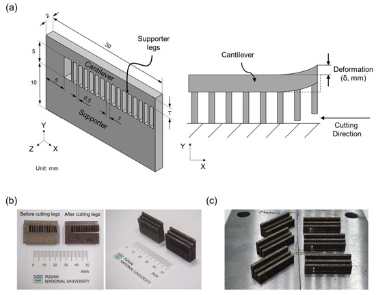
Figure 1.
(a) Modeling of cantilever specimen and schematic diagram of deformation measurement method used in this study. Cantilever specimens produced by LPBF (b) with artificial supporter and (c) directly on steel baseplate without supporter.
Aging heat treatments of the cantilever specimens were performed in a box-type electric furnace. The specimens were wrapped in a protective stainless-steel heat treatment foil to prevent severe oxidation. Some specimens underwent solution treatment for 2 h at 850 °C, air-cooled to a room temperature (22 °C), and then aged at 500 °C for 6 h. Other specimens were directly aged without solution heat treatment at 500 °C for 6 h. These two heat treatment conditions were chosen because it was shown that both these conditions can lead to a fully hardened state in the LPBF-processed maraging steel [9]. The mechanical properties obtained for the LPBF processed 18Ni-300 maraging steel treated with the above conditions are listed in Table 3.
Table 3.
Mechanical properties of LPBF processed 18Ni-300 maraging steel in different heat treatment conditions used in this study [9].
The baseplate material for the LPBF used in this study was medium-carbon steel with a carbon content of 0.4 wt.%, which is a commonly used baseplate material for the LPBF of Fe-based materials [25,26]. In some cases, stress-relieving heat treatment can be performed before cutting the LPBF-processed component from the baseplate to prevent the cutting induced distortions. For these cases, the different thermal shrinkage properties between the maraging steel and the medium-carbon steel baseplate may lead to a different residual stress state in comparison with a case of post-heat treatment after cutting the maraging component from the baseplate. To investigate such a baseplate effect, two different types of specimens were made in this study. The first type was the cantilever attached to the artificial supporter according to the design shown in Figure 1a. In this case the specimens were heat treated after cutting them from the baseplate, while they were still attached to the artificial supporters. Since artificial supporters were made by the same maraging steel as the cantilevers, it can be considered that there was no baseplate effect on these specimens during the heat treatments. These specimens are shown in Figure 1b. The second type of specimen was directly attached to the baseplate without an artificial supporter, as shown in Figure 1c. These specimens were heat treated together with the baseplate, while they were still attached. Hence, they can be influenced by the different thermal expansion and shrinkage responses of the baseplate to the maraging steel.
3. Results and Discussions
3.1. Residual Stress in As-Built State
Figure 2 shows the deformation, δ, measured when cutting the supporter legs of the maraging steel cantilevers with different thicknesses, T, in the as-built state. The evolutions of the deformations while cutting each supporter leg are shown in Figure 2a. When T = 0.5 mm, cutting the legs caused significant and gradually increasing downward distortions. This behavior is very interesting because, typically, the deformation of the cantilever occurs in an upward direction due to the tensile stress on the top and the compressive stress near the bottom, which are a general consequence of the thermal shrinkage of each layer [24,27,28]. In the case of T = 1.0 mm, the cantilever showed smaller but still significant downward deformations compared with T = 0.5 mm. When the thicknesses of the cantilevers were 2.5 and 5 mm, the cantilever showed small amounts of upward deformations instead of downward deformations. The final deformations measured for the cantilevers with various t after cutting all the supporter legs are shown in Figure 2b. It can be seen clearly that the downward deformation of the cantilever was highest when the cantilever was the thinnest (i.e., T = 0.5 mm). With increases in the cantilever thickness, the downward deformation decreased sharply until T = 1.25 mm, where almost no deformation was occurred. With further increases in the thickness, the deformation became upward, and the amount of the upward deformation increased moderately with increasing thickness.
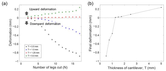
Figure 2.
(a) Deformation changes caused by cutting each leg of cantilevers with different thicknesses of T, in as-built state. (b) Final deformations of cantilevers with different thicknesses after cutting all supporter legs.
The downward deformation behavior of the thin cantilevers could be attributed to the compressive stress state at the top of the cantilever. The occurrence of the compressive stress at the top was also observed by the X-ray diffraction measurements of the maraging steel produced by LPBF by Mugwagwa et al. [22]. A possible cause of such a compressive stress state is the phase transformation from the body-centered tetragonal martensite to the face-centered cubic austenite that occurs during the LPBF process due to the intrinsic heat treatment (IHT) effect, which has been suggested and validated by phase transformation simulations by Baere et al. [23]. According to this mechanism, when each maraging steel layer is deposited, the layer is nearly fully composed of martensite phase due to the rapid cooling right after the deposition. Then, each layer is heated again several times when the next layers are deposited. In this situation, second and third heating can cause some amount of the austenite phase to be retained after the cooling due to the IHT effect. Since the martensite to austenite phase transformation occurs with significant volumetric expansion and only the top layer remains in a near fully martensite state, such a phase transformation can cause a compressive stress state at the top LPBF layer. A high-resolution scanning transmission electron microscopy of the maraging steel produced by LPBF has shown that the layers in the middle consisted of very thin (~100 nm) austenite phases between martensite pockets [29], which supports the fact that some austenite can be retained after multiple heating and cooling due to the IHT effect.
In the case of the maraging steel used in this study, the microstructural morphologies of the middle and the top layers were apparently the same, with solidification in the cell structures. For this reason, distinguishing the retained austenite phase in the middle layer by the morphological difference of the phase was not possible. However, the electron backscatter diffraction map of the maraging steel in the as-built state showed significant unindexed areas, which indirectly indicate the possibility of very thin austenite phases existing in the martensite matrix in the middle layers [9].
To analyze the downward deformation behavior caused by the compressive stress at the top layer, finite element (FE) simulations were conducted using a two-dimensional plane stress model of the cantilever. Figure 3 shows the geometry and FE meshes used in these simulations. The simulation model consisted of the cantilever and the supporter legs. The artificial supporter was not modeled in the simulation since the supporter does not have any influence on the distortion of the cantilever in the simulation. The geometries of the cantilever and the supporter legs were set to be the same as in the experiments. As shown in Figure 3a, the top LPBF layer of the cantilever was considered as the fully martensite area. The thickness of the top layer was assumed to be 0.04 mm since the layer thickness of each layer was set to 0.04 mm in the LPBF experiment. For the FE calculations, the model was meshed with 49,720 FE nodes and 15,109 elements (Figure 3b). The maraging steel was assumed as a linear elastic material, with an elastic modulus and Poisson’s ratio of 200 GPa and 0.33, respectively. The model was implemented on a commercial FE simulation package Ansys V19. Eight-noded 2D rectangular elements, Plane183 of Ansys, were used for the calculations.
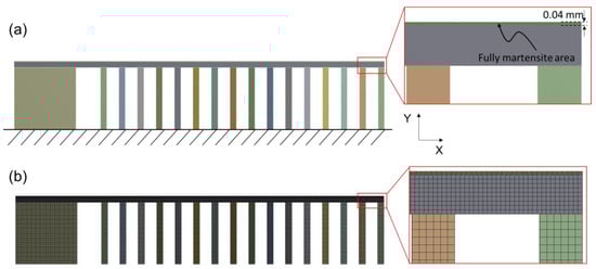
Figure 3.
FE simulation model for cantilever downward distortion for t = 0.5 mm. (a) A schematic of the model used in this study and (b) finite element meshes.
The simulations were carried out for the cantilevers while varying the thickness, T, of the model. In the first step of the FE simulations, a compressive 600 MPa normal stress was applied along the cantilever beam direction (i.e., x-direction) at the top layer of the cantilever (i.e., fully martensite area in Figure 3a) by linearly expanding the layer by 0.3% along the beam direction. This condition was chosen because the phase transformation simulation predicted about a 600 MPa compressive stress state in the top layer when the layer was fully in the martensite state [23]. At this step, the bottom surfaces of the supporter legs were constrained. In the second step, the constraint of the bottom surface of each supporter leg was removed sequentially one by one, according to the cutting procedure used in the experiment. The deformations of the cantilevers were determined by the vertical displacements of the top left edge of the model during the cutting process.
Figure 4 shows the equivalent stress contours before and after cutting the supporter legs as calculated by the FE model for a 0.5 mm thick cantilever. Because the thickness of the top layer is much thinner than the total thickness of the cantilever, a significant compressive stress state exists only at the top layer while the rest of the cantilever has very low stress, except near the top left edge where a small amount of stress was transferred from the top layer to the region below due to the bending effect. When cutting the supporter legs, the compressive stress state at the top layer induces pronounced downward deformation of the cantilever, as expected.
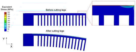
Figure 4.
Equivalent stress and deformation calculated by FE model before and after cutting supporter legs for 0.5 mm thick cantilever. The deformation is magnified by 10 times for better visualization.
The deformations predicted by the FE model with various t are compared with the corresponding experimental results, as shown in Figure 5. Figure 5a shows comparisons of evolutions of the deformations while cutting the supporter legs, between the FE simulations and the experiments. The simulations show slightly different trends in the deformation compared with the experiments as the number of legs cut increases. The slope of the deformation curve becomes more negative with an increasing number of legs cut in the simulations, whereas the experimentally obtained curves have relatively steady slopes compared with the simulations. However, the final deformations predicted by the simulations after cutting all the legs follow the same trend as those of the experiment. Figure 5b shows the final deformations after cutting all the supporter legs, obtained from the simulations and the experiments. It can be seen that the final deformation trends between the simulations and the experiments agree fairly well. Both the experiments and the simulations show trends of diminishing the downward deformation clearly when the thickness of the cantilever is increased from 0.5 to 1.5 mm.
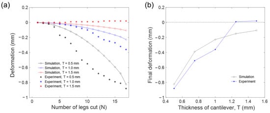
Figure 5.
Comparisons of deformations caused by cutting supporter legs, between FEM simulations and experiments. (a) Deformation changes caused by cutting each leg and (b) Final deformation after cutting all supporter legs.
The simulation results confirm that the main reason for the downward distortion of the thin maraging steel cantilever is the phase transformation of the maraging steel from martensite to austenite during the LPBF, which occurs due to the IHT effect, except on the top layer. It was also found that the deformations predicted by the simulations had slight deviations from the experimental results. These deviations are probably caused by the inhomogeneous residual stress distribution in the maraging steel cantilever caused by the LPBF, which was neglected in the highly idealized FE model of this study. As pointed out by Baere et al. [23], each LPBF layer of the maraging steel have experienced multiple reheats to above the austenite transformation temperature except for the top layer. The reheating generates retained austenite and causes the volumetric contraction of each layer, with occurrences of compressive stress at the top layer and a complex stress state in the layers below. This complex effect was idealized by the compressive stress at the top layer in the current FE simulations, which probably resulted in the deviations between the experimental and simulated deformation behaviors shown in Figure 5.
3.2. Effect of Aging Heat Treatment
Figure 6 shows the deformations of the cantilever specimens while cutting the supporter legs, after the aging heat treatments. The heat treatments of the cantilevers were carried out for the specimens with the artificial supporter (i.e., shown in Figure 1b), thus both the cantilevers and the supporters were made by the LPBF-processed maraging steel in this case. Figure 6a shows the deformations caused by cutting each supporter leg of the cantilevers, heat treated with direct aging at 500 °C for 6 h, without the solution heat treatment. Unlike the case of the as-built state in which the thin cantilevers showed significant downward distortions, the heat-treated cantilevers showed upward distortions regardless of the thickness of the cantilever, as shown in Figure 6a. It can be seen that the upward distortion tends to increase with increasing the thickness of the cantilever.
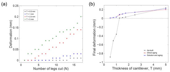
Figure 6.
Deformations caused by cutting supporter legs after aging heat treatment. (a) Deformation changes caused by cutting each leg of cantilevers, in direct aging state. (b) Final deformations of cantilevers after cutting all supporter legs in different aging heat treatment conditions.
Figure 6b shows the final deformations after cutting all the supporter legs for the maraging steel cantilevers in three different heat treatment states, as-built, direct aging without solution heat treatment, and aging followed by the solution heat treatment. The aging heat-treated cantilevers showed negligible deformations when the thickness of the cantilevers were 0.5 mm. The deformations increased slightly and continuously with increasing cantilever thickness. The final deformations for the cantilevers with various thicknesses were nearly identical between the aging heat-treated specimens with and without solution heat treatment at 850 °C for 2 h, indicating that the solution heat treatment does not have any influence on the residual stress state of the cantilever after the aging heat treatment. This means that the aging heat treatment at 500 °C for 6 h is able to almost completely relieve the residual stress that occurred during the LPBF process. This result indicates that solution heat treatment is not necessary for the purpose of residual stress relief for the maraging 18Ni-300 steel components produced by the LPBF.
Due to the limited number of samples used for the investigation, only one cantilever sample for each condition was subjected to the test. Thus, possible deviations associated with experimental error have not been accessed. However, when considering the nearly identical final deformation behaviors between the cantilevers in two different aging heat treatment states of direct aging and aging followed by the solutioning, the deformations that occurred in the aging heat-treated cantilever specimens were probably not a result of experimental error. These near-identical deformations obtained from differently heat-treated samples also reflect the fairly good reproducibility of the cantilever method used for this study.
One possible cause of the upward deformations in the heat-treated cantilevers is the small amount of residual stress that cannot be completely removed by the heat treatment. Another possible cause of the upward deformation could be the precipitations and lattice distortions occurring in the aging heat treatment. As shown in the authors’ previous work [9], the maraging steel incurs fine intermetallic compounds as precipitates during the aging which can cause a volumetric change in the maraging steel by the lattice distortion near the precipitate or by the lattice parameter change in the matrix due to the change in solute concentration. Nevertheless, the number of upward distortions after the heat treatment was trivial when comparing them with the downward distortions observed in the thin cantilevers in the as-built state. Considering the length of the cantilever beam of 25 mm used in this study, the maximum distortion of ~0.2 mm obtained by the 5 mm thick cantilever in the upward direction corresponds to a cantilever radius of ~1560 mm. An analytical expression that correlates the strain misfit between each layer, εs, to the cantilever distortion is given by [27]:
where tl is the thickness of each layer, R is the radius of the cantilever after cutting the supporter legs and N is the number of layers. The εs value calculated using the above equation yields ~8.6 × 10⁻⁶ mm/mm for t = 0.04 mm and N = 125 used in the experiment for the 5 mm thick cantilever specimen. Assuming an elastic modulus of the maraging steel of 200 GPa, this amount of elastic strain misfit corresponds to ~1.7 MPa of the stress which is negligible when considering the high yield strength of the maraging steel after the aging heat treatment of over 1800 MPa [9].
3.3. Baseplate Effect
In this section, the final cantilever deformations after cutting all the supporter legs were compared with the cases of the cantilevers attached on the artificial supporter and the baseplate during the heat treatments. Figure 7 shows the final deformations of the cantilevers with various thicknesses after the aging heat treatments. The deformations shown in Figure 7a are from the cantilevers that were aging heat treated while they were attached on the artificial supporters made by the maraging steel, whereas in Figure 7b, the deformations of the cantilevers attached to the medium-carbon steel baseplate directly by the legs during the heat treatments are shown. The results shown in Figure 7 evidently indicate that the aging heat treatment with the medium-carbon steel baseplate does not alter the residual stress state compared with the case of the aging heat treatment of all the maraging steel components. As can be seen in Figure 7, the deformations observed in the cantilevers that were heat treated on the maraging steel artificial supporters depend only on the thickness of the cantilever, but not on the baseplate or the artificial supporter on which they were attached during the heat treatment. This behavior is clearly indicated by Figure 7, where the cantilevers heat treated with the steel baseplate show almost identical deformations compared with the cantilevers heat treated with the artificial supporters.
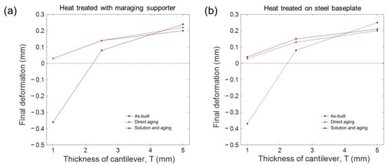
Figure 7.
Comparisons of deformations caused by cutting supporter legs, between cantilevers heat treated with maraging supporter and directly on steel baseplate. (a) Cantilevers heat treated with maraging supporter and (b) heat treated directly on steel baseplate.
The results shown in Figure 7 indicate that the stress relieving heat treatment of the maraging 18Ni-300 steel components produced by the LPBF can be performed while they are attached to carbon steel baseplates, without any special consideration of the thermal strain misfit effect due to the dissimilar material joint between the maraging components and the steel baseplate. This is probably because the stress relieving of the maraging steel can occur at a relatively low aging temperature of 500 °C. At such a low temperature, the carbon steel is in a ferritic state since the temperature is below the A1 temperature and stays in the same state while cooling to room temperature after the aging heat treatment. The maraging steel is expected to be in the same ferritic state in the temperature range between 22 and 500 °C since the austenite transformation start temperature of the LPBF-processed maraging steel is about 620 °C [30]. Therefore, it is expected that both the maraging steel component and the carbon steel baseplate will be in the ferritic states during the aging heat treatment and cooling without any significant phase transformation-induced volumetric change.
4. Summary
The effect of a heat treatment condition on the residual stress state of maraging 18Ni-300 steel produced by LPBF was investigated. Cantilever-shaped specimens were fabricated to quantify the residual stress by measuring their distortions when cutting them from the supporters. The main findings of this study can be summarized as follows:
- In the as-built state, the LPBF-processed maraging steel cantilevers showed complex distortion behavior while cutting them from the supporter. They bent downward significantly when the thickness of the cantilever was relatively thin. It was believed that the downward distortions of the thin cantilevers were due to the phase transformation of the maraging steel from martensite to austenite during the LPBF due to the IHT effect, which occurred in all regions, except on the top LPBF layer, and produced a compressive stress state on the top layer. FE simulations were carried out based on the assumption of the compressive stress state of the top layer. The deformation trends predicted by the simulations agreed fairly well with the experiments, indicating that the main reason for the downward distortion of the cantilever is the phase transformation due to the IHT effect.
- The effect of direct aging without solution heat treatment on the residual stress relief behavior was analyzed by comparing the distortions of the directly aged cantilevers without solution heat treatment with those that were aging heat treated followed by the solution heat treatment. It was found that aging heat treatment can effectively diminish the downward distortions of the cantilevers, in both cases with and without solution heat treatment. Thus, the results indicate that the solution heat treatment is not necessary for the purpose of residual stress relieving for the maraging 18Ni-300 steel components produced by the LPBF.
- The effect of the LPBF baseplate made of medium-carbon steel on the residual stress relief behavior during the heat treatment was investigated by producing the cantilevers directly attached to the medium-carbon steel baseplate. These cantilevers were aging heat treated while they were still attached to the baseplate. Comparisons of the distortions of these cantilevers with those attached to the maraging steel artificial supporter structures showed that the carbon steel baseplate does not have any influence on stress relief behavior. Almost identical distortion behaviors were observed for the cases of the cantilevers heat treated with the maraging steel artificial supporter and with the carbon steel baseplate. This indicates that the stress relieving heat treatment of the maraging 18Ni-300 steel components produced by the LPBF can be performed while they are attached to carbon steel baseplates without any special consideration of the thermal strain misfit effect due to the dissimilar material joint between the maraging components and the steel baseplate.
Author Contributions
Conceptualization, J.H.Y. and W.L.; methodology, J.H.Y. and K.H.; formal analysis, J.H.Y. and Q.-Y.J.; investigation, J.H.Y., Q.-Y.J. and K.H.; resources, W.L.; writing—original draft preparation, J.H.Y. and W.L.; writing—review and editing, Q.-Y.J. and W.L.; visualization, Q.-Y.J. All authors have read and agreed to the published version of the manuscript.
Funding
This work was supported by a two-year research grant from the Pusan National University.
Institutional Review Board Statement
Not applicable.
Informed Consent Statement
Not applicable.
Data Availability Statement
The data that support the findings of this study are available from the corresponding author, W.L., upon reasonable request.
Conflicts of Interest
The authors declare no conflict of interest.
References
- Moshka, O.; Pinkas, M.; Brosh, E.; Ezersky, V.; Meshi, L. Addressing the issue of precipitates in maraging steels—Unambiguous answer. Mater. Sci. Eng. A 2015, 638, 232–239. [Google Scholar] [CrossRef]
- Béreš, M.; Wu, L.; Santos, L.P.M.; Masoumi, M.; da Rocha Filho, F.A.M.; da Silva, C.C.; de Abreu, H.F.G.; Gomes da Silva, M.J. Role of lattice strain and texture in hydrogen embrittlement of 18Ni (300) maraging steel. Int. J. Hydrogen Energy 2017, 42, 14786–14793. [Google Scholar] [CrossRef]
- Avelino, A.F.; Araújo, W.S.; Dias, D.F.; dos Santos, L.P.M.; Correia, A.N.; de Lima-Neto, P. Corrosion investigation of the 18Ni 300 grade maraging steel in aqueous chloride medium containing H2S and CO2. Electrochim. Acta 2018, 286, 339–349. [Google Scholar] [CrossRef]
- King, W.E.; Anderson, A.T.; Ferencz, R.M.; Hodge, N.E.; Kamath, C.; Khairallah, S.A.; Rubenchik, A.M. Laser powder bed fusion additive manufacturing of metals; physics, computational, and materials challenges. Appl. Phys. Rev. 2015, 2, 041304. [Google Scholar] [CrossRef]
- Yap, C.Y.; Chua, C.K.; Dong, Z.L.; Liu, Z.H.; Zhang, D.Q.; Loh, L.E.; Sing, S.L. Review of selective laser melting: Materials and applications. Appl. Phys. Rev. 2015, 2, 041101. [Google Scholar] [CrossRef]
- Jägle, E.A.; Sheng, Z.; Kürnsteiner, P.; Ocylok, S.; Weisheit, A.; Raabe, D. Comparison of Maraging Steel Micro- and Nanostructure Produced Conventionally and by Laser Additive Manufacturing. Materials 2016, 10, 8. [Google Scholar] [CrossRef] [PubMed]
- Bae, K.C.; Kim, D.; Kim, Y.H.; Oak, J.J.; Lee, H.; Lee, W.; Park, Y.H. Effect of heat treatment, building direction, and sliding velocity on wear behavior of selectively laser-melted maraging 18Ni-300 steel against bearing steel. Wear 2021, 482–483, 203962. [Google Scholar] [CrossRef]
- Bae, K.; Kim, D.; Lee, W.; Park, Y. Wear behavior of conventionally and directly aged maraging 18ni-300 steel produced by laser powder bed fusion. Materials 2021, 14, 2588. [Google Scholar] [CrossRef]
- Kim, D.; Kim, T.; Ha, K.; Oak, J.J.; Jeon, J.B.; Park, Y.; Lee, W. Effect of heat treatment condition on microstructural and mechanical anisotropies of selective laser melted maraging 18Ni-300 steel. Metals 2020, 10, 410. [Google Scholar] [CrossRef]
- Conde, F.F.; Escobar, J.D.; Oliveira, J.P.; Jardini, A.L.; Bose Filho, W.W.; Avila, J.A. Austenite reversion kinetics and stability during tempering of an additively manufactured maraging 300 steel. Addit. Manuf. 2019, 29, 100804. [Google Scholar] [CrossRef]
- Kladaric, I.; Krumes, D.; Markovic, R. The Influence of Multiple-Solution Annealing on Kinetics of Structural Transformation of Maraging Steels. Mater. Manuf. Process. 2007, 21, 783–785. [Google Scholar] [CrossRef]
- Viswanathan, U.K.; Dey, G.K.; Asundi, M.K. Precipitation hardening in 350 grade maraging steel. Metall. Trans. A 1993, 24, 2429–2442. [Google Scholar] [CrossRef]
- Xu, X.; Ganguly, S.; Ding, J.; Guo, S.; Williams, S.; Martina, F. Microstructural evolution and mechanical properties of maraging steel produced by wire + arc additive manufacture process. Mater. Charact. 2018, 143, 152–162. [Google Scholar] [CrossRef]
- Tan, C.; Zhou, K.; Ma, W.; Zhang, P.; Liu, M.; Kuang, T. Microstructural evolution, nanoprecipitation behavior and mechanical properties of selective laser melted high-performance grade 300 maraging steel. Mater. Des. 2017, 134, 23–34. [Google Scholar] [CrossRef]
- Kempen, K.; Yasa, E.; Thijs, L.; Kruth, J.P.; Van Humbeeck, J. Microstructure and mechanical properties of Selective Laser Melted 18Ni-300 steel. Phys. Procedia 2011, 12, 255–263. [Google Scholar] [CrossRef]
- Yin, S.; Chen, C.; Yan, X.; Feng, X.; Jenkins, R.; O’Reilly, P.; Liu, M.; Li, H.; Lupoi, R. The influence of aging temperature and aging time on the mechanical and tribological properties of selective laser melted maraging 18Ni-300 steel. Addit. Manuf. 2018, 22, 592–600. [Google Scholar] [CrossRef]
- Michaleris, P. Modeling metal deposition in heat transfer analyses of additive manufacturing processes. Finite Elem. Anal. Des. 2014, 86, 51–60. [Google Scholar] [CrossRef]
- Robinson, J.; Ashton, I.; Fox, P.; Jones, E.; Sutcliffe, C. Determination of the effect of scan strategy on residual stress in laser powder bed fusion additive manufacturing. Addit. Manuf. 2018, 23, 13–24. [Google Scholar] [CrossRef]
- Ha, K.; Kim, T.; Baek, G.Y.; Jeon, J.B.; Shim, D.; Moon, Y.H.; Lee, W. Numerical study of the effect of progressive solidification on residual stress in single-bead-on-plate additive manufacturing. Addit. Manuf. 2020, 34, 101245. [Google Scholar] [CrossRef]
- Webster, G.A.; Ezeilo, A.N. Residual stress distributions and their influence on fatigue lifetimes. Int. J. Fatigue 2001, 23, 375–383. [Google Scholar] [CrossRef]
- Vrancken, B.; Wauthlé, R.; Kruth, J.-P.; Van Humbeeck, J. Study of the influence of material properties on residual stress in selective laser melting. In Proceedings of the Solid Freeform Fabrication Symposium, Austin, TX, USA, 12–14 August 2013; pp. 393–407. [Google Scholar]
- Mugwagwa, L.; Yadroitsev, I.; Matope, S. Effect of Process Parameters on Residual Stresses, Distortions, and Porosity in Selective Laser Melting of Maraging Steel 300. Metal 2019, 9, 1042. [Google Scholar] [CrossRef]
- De Baere, D.; Moshiri, M.; Smolej, L.; Hattel, J.H. Numerical investigation into laser-based powder bed fusion of cantilevers produced in 300-grade maraging steel. Addit. Manuf. 2022, 50, 102560. [Google Scholar] [CrossRef]
- Jin, Q.Y.; Kang, D.; Ha, K.; Yu, J.H.; Lee, W. Simulation of annealing process on AISI 316 L stainless steel fabricated via laser powder bed fusion using finite element method with creep. Addit. Manuf. 2022, 60, 103255. [Google Scholar] [CrossRef]
- Murkute, P.; Pasebani, S.; Burkan Isgor, O. Metallurgical and Electrochemical Properties of Super Duplex Stainless Steel Clads on Low Carbon Steel Substrate produced with Laser Powder Bed Fusion. Sci. Rep. 2020, 10, 10162. [Google Scholar] [CrossRef] [PubMed]
- Franke-Jurisch, M.; Mirz, M.; Wenz, T.; Kirchner, A.; Klöden, B.; Weißgärber, T. PBF-EB of Fe-Cr-V Alloy for Wear Applications. Materials 2022, 15, 1679. [Google Scholar] [CrossRef]
- Safronov, V.A.; Khmyrov, R.S.; Kotoban, D.V.; Gusarov, A.V. Distortions and residual stresses at layer-by-layer additive manufacturing by fusion. J. Manuf. Sci. Eng. Trans. ASME 2017, 139, 3–8. [Google Scholar] [CrossRef]
- Kim, T.; Ha, K.; Cho, Y.R.; Jeon, J.B.; Lee, W. Analysis of residual stress evolution during powder bed fusionprocess of AISI 316L stainless steel with experiment and numerical modeling. Int. J. Adv. Manuf. Technol. 2019, 105, 309–323. [Google Scholar] [CrossRef]
- Dehgahi, S.; Ghoncheh, M.H.; Hadadzadeh, A.; Sanjari, M.; Amirkhiz, B.S.; Mohammadi, M. The role of titanium on the microstructure and mechanical properties of additively manufactured C300 maraging steels. Mater. Des. 2020, 194, 108965. [Google Scholar] [CrossRef]
- Król, M.; Snopiński, P.; Czech, A. The phase transitions in selective laser-melted 18-NI (300-grade) maraging steel. J. Therm. Anal. Calorim. 2020, 142, 1011–1018. [Google Scholar] [CrossRef]


Disclaimer/Publisher’s Note: The statements, opinions and data contained in all publications are solely those of the individual author(s) and contributor(s) and not of MDPI and/or the editor(s). MDPI and/or the editor(s) disclaim responsibility for any injury to people or property resulting from any ideas, methods, instructions or products referred to in the content. |
© 2023 by the authors. Licensee MDPI, Basel, Switzerland. This article is an open access article distributed under the terms and conditions of the Creative Commons Attribution (CC BY) license (https://creativecommons.org/licenses/by/4.0/).