Abstract
Soft continuum robots and manipulators (SCRaMs) are elongated structures that can be used in many applications, such as exploration, inspection, and minimally invasive surgery. Multi-segment SCRaMs employ numerous actuators to perform their tasks. The large number of actuators increases the cost and complexity of a SCRaM and reduces its reliability. In this paper, a methodology is presented to reduce the number of actuators employed by SCRaMs while maintaining their volumetric workspace. The method presents a new design approach involving one rotary and two linear actuators, providing three degrees of freedom (DOF) and a volumetric workspace. The result of applying the transformation is a 50–86% reduction in the total number of actuators typically employed by multi-segment SCRaMs. The application of this methodology reduces the cost and complexity of conventional multi-segment SCRaMs while improving their efficiency and reliability.
1. Introduction
1.1. Background
Soft continuum robots and manipulators (SCRaM) are elongated shape mechanisms [1] which can be used for many applications such as inspection [2], minimally invasive surgery [3], and others [4,5,6]. The diverse range of applications is due to the large possible configurations of body dimensions, composition, cross-section, and actuation schemes.
SCRaMs operate by bending one or more of their body segments to approach the desired location. A bending segment in a SCRaM refers to the body section between two ends of a linear actuator. When the actuator retracts, the relative body segment bends in the direction of the retracting actuator. SCRaMs can be divided into single and multi-segment types, depending on the number of bending body segments. Hence, single segment SCRaMs can achieve only one curvature across their whole body, while multi-segment SCRaMs can produce multiple curvatures, corresponding to the number of bending sections in their bodies.
1.2. Problem and Research Aim
To improve their dexterity, SCRaMs employ more bending segments. In some works, such as [7,8,9], six, nine, and twelve actuators, respectively, were used to drive the manipulators, while Y. Goergen et al. employed twenty-one actuators, distributed over seven segments, to operate the robot and give it the required workspace and dexterity [10]. The employment of a large number of actuators improves the dexterity of SCRaMs; however, it also increases the cost, complexity, and energy requirements while reducing the overall reliability of the SCRaM. To solve this issue, fixed-length, single-segment (FLSS) SCRaMs were presented, employing a reduced number of actuators, allowing them to reduce the cost and complexity of the system, as presented by Santoso, J. [11] and Xu, F. et al. [12]. However, FLSS-SCRaMs offer reduced dexterity and workspace in comparison to multi-segment SCRaMs, as demonstrated by works [13,14], in comparison to [15,16].
In order to avail the benefits of FLSS-SCRaMs while maintaining the advantages of multi-segment SCRaMs, this work aims to present a method to reduce the number of employed actuators while preserving or improving the SCRaM’s workspace and maintaining a practical level of dexterity. This work aims to achieve this goal by reconfiguring a SCRaM actuator arrangement and substitute one of the SCRaM’s linear actuators with a rotary type.
1.3. Other Works
Due to its many benefits, the interest in reducing the number of actuators in the robotics field is not new. Many researchers have attempted to present designs that achieve similar performance to then-current systems while employing fewer actuators. In past literature, such as works presented by [17,18,19], attempts were made by researchers to reduce the number of employed actuators while maintaining the dexterity and workspace of the robotic system.
In the field of cable-driven robotics, it was determined that the minimum number of tendons required for a modular cable-driven robotic arm (MCDRA) is n + 1, where n represents the number of the robot’s degrees of freedom (DOF) [20]. Hence, a SCRaM requires a minimum number of four cables (actuators) to possess three DOF to cover a volumetric workspace. Accordingly, several works aimed to reduce the number of actuators by merging actuator responsibilities. Wang, Y., et al. proposed a method that employed sharing the same actuator by adjacent cable-driven joints [21]. Case, J.C., et al., on the other hand, reduced the number of actuators in a planar continuum manipulator by crossing the cables through the manipulator’s body, thus achieving the same workspace with fewer actuators [22]. Although these designs provide a reduction in the number of employed actuators, the reduction ratio was only 22.2% in [21] and 33.3% in [22]. Wang, Y., et al. proposed a one and two co-shared driving cable approach to reduce the number of independently actuated cables for a modular cable-driven manipulator (MCDM) [23]. The proposed approach managed to maintain the manipulator’s workspace while sharing one cable; however, the workspace can only be maintained for two co-shared cables if non-empty intersections exist for each joint module.
1.4. Contribution
This work contributes a novel design methodology that reconfigures a SCRaM instead of merging the responsibilities of its actuator. This work presents a novel approach to the goal of actuator reduction through the substitution of one linear actuator with a rotary alternative and removing other redundant linear actuators from the SCRaM. The process allows a soft continuum manipulator to possess three DOF using only three actuators, thus achieving n DOF through n actuators, resulting in a minimum reduction of 25% in the number of required actuators by SCRaMs while maintaining their workspace. The presented method allows a SCRaM to employ three actuators in comparison to typical multi-segment SCRaMs, thus achieving a 50%, 66%, and 75% reduction in comparison to other SCRaMs, such as [7,8,9], respectively. Furthermore, the reduction ratio reaches 86% in comparison to SCRaMs employing 21 actuators to drive their seven body segments, such as [10].
In addition to reducing the number of employed actuators, the presented manipulator maintains a volumetric workspace matching those reported by some multi-segment SCRaMs, such as [24], and exceeding others, such as [16,25]. Hence, the significance of the presented method is the achievement of a relatively high actuator reduction ratio in SCRaMs without sacrificing their workspace. Accordingly, the presented actuator reduction method reduces the cost and complexity of a SCRaM and improves its efficiency and reliability by reducing the number of actuators and other moving parts while maintaining or improving the SCRaMs’ required workspace.
The reduction in the number of actuators reduces the cost, complexity, and weight of the SCRaM in addition to a large workspace, making it useful for a diverse set of applications that largely benefit from these traits. The reduced cost of the manipulator could be employed to fabricate a large horizontal version to be used for constraining floating sea junk or oil spills. The simplicity of the design could be realized in the teleoperation of the manipulator for the inspection of tall or submerged structures. Moreover, the lightweight feature is especially attractive for producing manipulators intended for space deployment.
1.5. Article Layout
The rest of this paper is organized as follows: Section 2 describes the actuator reduction method. Section 3 presents the design of a soft continuum manipulator based on the reduction method. Section 3 also provides a validation of the proposed method through a mathematical model and a finite element analysis (FEA) simulation to provide an indication of the manipulator’s workspace. Finally, Section 5 provides an overview of the performed work, including its strengths, limitations, and potential applications and suggestions for future work.
2. Actuator Reduction
2.1. Methodology Overview
A linear actuator connects the tip of a SCRaM to a point along its body. When the actuator retracts, it causes the body to bend in the actuator’s direction and the tip to follow a certain path, as shown in Figure 1. Hence, the location of the SCRaM’s tip can be referred to as:
where T is the planar location of the manipulator’s tip and a is the length of the actuator. In Figure 2a, a linear actuator is attached to the two ends of the SCRaM’s body. However, if the actuator’s second attachment point (SAP) is moved along the body, as illustrated in Figure 2b,c, then the initial length of the actuator changes, hence:
where a is the length of the actuator and p is the location of the second attachment point along the body of the SCRaM. By combining Equations (1) and (2), we obtain:
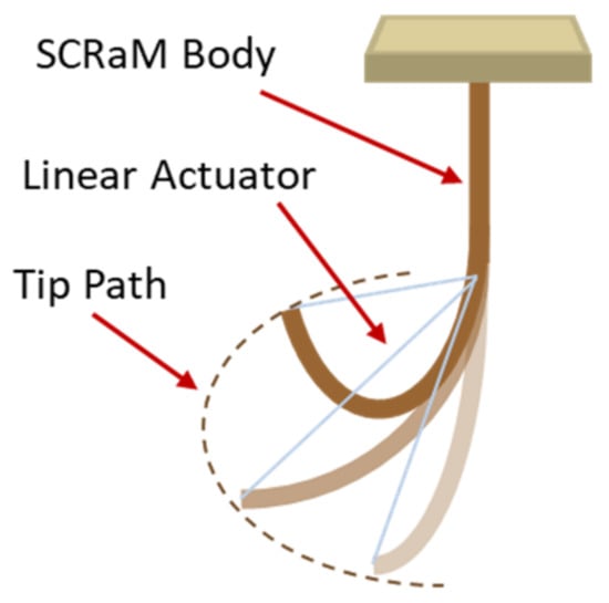
Figure 1.
The SCRaM’s tip follows a path as the linear actuator retracts.
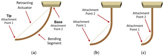
Figure 2.
Different actuator attachment points create different bending segment lengths: (a) Initial location of the SAP. (b) SAP moved to two-thirds of the body. (c) SAP at one-third of the body.
From Equation (3), a planar workspace emerges from altering the actuator’s second attachment point and then retracting the actuator to cause a bending in the SCRaM’s body. If the base of the SCRaM is mounted on a rotary actuator, then Equation (3) can be modified to become:
where θ is the rotation angle of the base actuator. The location of the tip T in Equation (4) is defined by three DOF, and hence indicate a volumetric workspace, as illustrated in Figure 3.
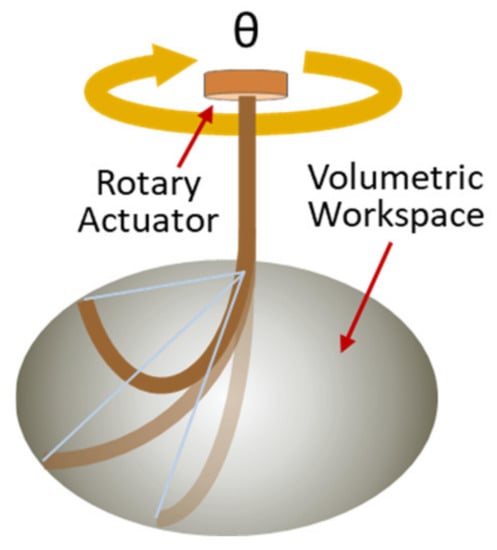
Figure 3.
Adding a rotary actuator at the manipulator’s base results in a volumetric workspace.
2.2. Actuator Reduction Steps
The steps to reduce the number of actuators are as follows: First, all the SCRaM’s actuators are removed, and then a sliding part is installed on the body of the SCRaM. The sliding part would be used to alter the length of the bending segment. A linear actuator is used to move the sliding part by connecting it to the manipulator’s base. If the used actuator is a tendon, then its driving motor could be placed at the SCRaM’s base. Another linear actuator is used to connect the SCRaM’s tip to the sliding part. If a tendon is used for this connection, then its motor could also be placed at the SCRaM’s base and the tendon routed from the motor, through the sliding part, to the tip of the SCRaM. However, if another type of linear actuator is used to pull the SCRaM’s tip, then an arrangement should be made to change the initial length of the actuator to match the length of the bending-segment below the sliding part. Finally, a rotary actuator is placed at the SCRaM’s base and used to rotate the manipulator to any direction, thus producing a 3D workspace. Figure 4 shows the process in the form of a flowchart.
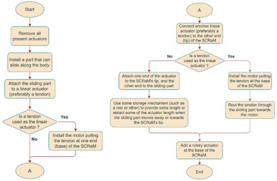
Figure 4.
Steps to reduce the number of actuators in multi-segment SCRaMs.
3. Validation
To validate the methodology, a manipulator was designed. Then, its workspace was calculated through a mathematical model and further confirmed through a finite element analysis (FEA) simulation. The model confirms the validity of the method through the calculation of the full workspace without considering manipulator statics or geometry, while the simulation provides a more relevant approximation of the manipulator’s performance.
3.1. Manipulator Design
The design process started by selecting a smooth continuous body, as this facilitates the movement of the sliding part. Discrete, corrugated, and origami bodies would hinder the motion of the sliding part. As for the body’s cross-section, the circular shape allows for even bending in all directions; however, the present manipulator only bends in one direction, therefore a thin–wide cross-section is preferred, as it requires less energy to bend, can easily achieve full-loop curvatures, and provides a level of lateral rigidity. However, using a thin–wide cross-section dictates that the manipulator be in a suspended posture to avoid its collapse. For actuation, tendons were selected, as they provide the highest retraction ratio, simplicity, precision, and routing ability.
Based on the selected configuration, the manipulator would have a tendon to pull the tip, another tendon to relocate the second attachment point of the first tendon, and finally, a motor at the base to rotate the whole manipulator, thus achieving three DOF, and therefore a volumetric workspace. By applying the selected configuration, a broad design for the manipulator emerges, as illustrated in Figure 5. Being suspended, the manipulator has a straight posture when relaxed and curved when the first tendon is activated through motor 1. The sliding part is driven by the second tendon through motor 2. The sliding part constrains the arm at its location, resulting in a curved arm segment below and a straight unactuated segment above. The tendon pulling the arm’s tip is routed through the sliding part towards its relative motor at the manipulator’s upper base. Hence, the sliding part can be referred to as an arm constrainer and tendon router (ACTR). Through this design, the manipulator has three DOF, provided by the one rotary and two linear actuators.
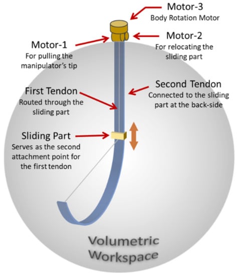
Figure 5.
Manipulator concept based on the methodology and selected configuration. The tendon pulling the manipulator’s tip is routed through the ACTR towards the relative motor at the base.
3.2. Workspace Calculation
To validate the manipulator’s workspace, a mathematical model was used to calculate the manipulator’s workspace without the effects of gravity, arm material, or geometry. Figure 6 depicts the manipulator’s arm under the influence of the retracted tendon. For simplicity, the depiction shows only one linear actuator. The motion effect of the other two actuators is shown by the thick red arrows.
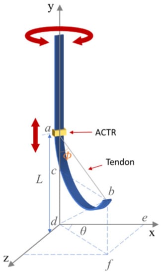
Figure 6.
A sketch depicting the setup of the manipulator with a single external actuator. The ACTR can be relocated anywhere along the manipulator’s body.
In this model, L represents the length of the bending segment, ab represents the tendon’s length between the two ends of the bending segment, and cd represent the tip’s displacements in Y axis direction. Initially, at rest position, the bending segment’s length L is calculated as:
When the tendon retracts and the manipulator bends, an angle φ is generated between the tendon and the vertical line representing the manipulator’s body at rest, thus:
Equation (9) provides the Y axis’ (vertical) displacement of the manipulator’s tip. In Figure 6, angle θ represents the manipulator’s rotation around the Y axis; hence, de and ef provide the X and Z axes’ displacements respectively.
The volumetric workspace of the manipulator can be obtained by using Equations (9) and (10), and by stepping through the values of φ and θ, as illustrated in Figure 7.
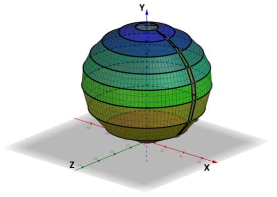
Figure 7.
The manipulator’s volumetric workspace based on the mathematical model calculations.
3.3. Computer Simulation
The computer simulation provided a more accurate approximation of the manipulator’s workspace as it took into consideration the geometry and material of the manipulator. The simulation employed a similar configuration for the arm tendon retraction mechanism. To simplify the simulation, the pulley retracting the arm tendon was placed on the ACTR, rather than the top base of the manipulator. The simulation was performed through finite element analysis (FEA) using SolidWorks [26].
The simulation process involved two steps. The first was to convert the manipulator design into a computer-assisted design (CAD) model, while the second step employed FEA to calculate the performance of the CAD model and its response during operation. In the first step, each component was created separately, and then all the components were assembled to form the manipulator. Table 1 provides a list of the components used in the simulation. The dimensions used in the assembly reflected the physical manipulator to be fabricated; hence, the arm was 500 mm long, 100 mm wide, and 0.8 mm thick. To facilitate layering on the winch pulley, the tendon was simulated as a band with a width of 6 mm and a thickness of 0.1 mm. The arm-tip pulley provided directional freedom for the arm’s distal end as the angle of the arm’s tip changed from zero to over 90 degrees during the simulation.

Table 1.
List of parts and their purpose in the FEA simulation.
The second step of the simulation involved specifying the settings to correspond to the real-life boundary conditions. Hence, the manipulator’s top end was fixed, while its lower end was free to move in response to the tendon’s pulling. The ACTR was fixed to provide a stable tendon retraction. Figure 8 illustrates the simulation and the response of the arm when the ACTR is 250 mm from the lower end of the arm.
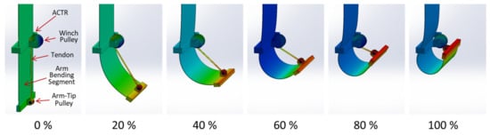
Figure 8.
The manipulator during FEA simulation. The images indicate the bending percentage.
The materials chosen for the arm and other components reflected the ones that would be used to fabricate the manipulator. Since most of the manipulator parts would be 3D printed, Acrylonitrile Butadiene Styrene (ABS) was used for most of the parts in the simulation. Polycarbonate plastic would be used to fabricate the arm due to both its flexibility and high tensile strength. Table 2 lists the materials used and their properties.
Table 2.
Objects’ material type for the FEA simulation.
The meshing resolution in the simulation was set differently for each component based on size, location, and level of stress the component may experience. High-resolution meshing was used for the ends of the tendon, as it pulls the arm’s tip, and thus experiences the highest stresses relative to its size. Relatively coarse meshing was used for the arm’s body and ACTR due to their size and the relatively mild stresses they would experience. Table 3 lists the different meshing resolutions for each component.
Table 3.
Mesh resolution for manipulator components and connection points.
The FEA test started with the manipulator at its default resting position. The test commenced with the rotation of the winch pulley, which retracted the tendon and pulled the manipulator’s lower end. The retracting tendon, in turn, pulled the arm from its tip pulley. The retraction of the tendon continued until the arm completed a full-loop and the arm’s tip reached the winch pulley. The number of winch-pulley rotations were determined through the following equation:
where N is the number of winch-pulley rotations, L is the length of the bending segment, representing the arm section below the ACTR, and r is the radius of the winch-pulley. The ACTR in Figure 8 represents the tendon’s second attachment point. To obtain the response of the manipulator’s arm for different bending segment lengths, the FEA test was performed for three ACTR locations: 100, 250, and 400 mm. These locations produced bending segments that are 20%, 50%, and 80% of the arm’s full length. The different bending segment lengths provided different trajectories of the arm’s tip in a planar workspace, as shown in Figure 9a. The tip trajectory depends on the location of the ACTR which determines the length of the bending segment. Accordingly, the variable location of the ACTR produces a planar workspace, as shown in Figure 9b. By applying θ values covering the full rotation of the manipulator about its vertical axis, a volumetric workspace emerges, as illustrated by Figure 10.
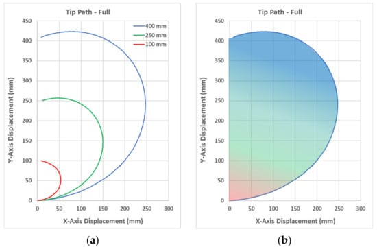
Figure 9.
The results obtained from the simulation: (a) Arm tip trajectories for three bending segment lengths. (b) Planar workspace.
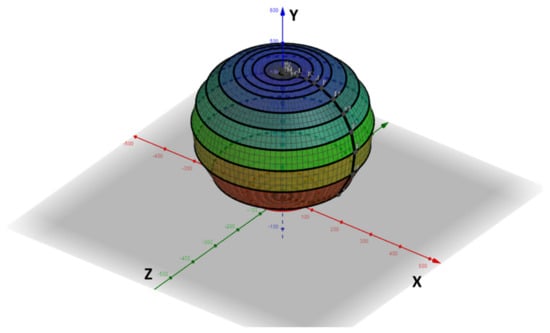
Figure 10.
The manipulator’s volumetric workspace based on the simulation results.
4. Discussion
4.1. Results Analysis
The results obtained from the mathematical model and FEA simulation confirmed the attainment of a volumetric workspace through the three DOF provided by the three actuators, essentially approving the validity of the actuator reduction method. The examination of Figure 8 indicated a buckling of the arm under the pulling force of the tendon, which reduced the horizontal reach of the manipulator. By comparing the shape of the workspaces in Figure 7 and Figure 10, a difference can be noticed: the model’s workspace is spherical, while the simulation’s workspace is analogous to an apple. This difference can be attributed to the simulation’s consideration of the arm’s material and geometry, as well as the effect of the arm’s buckling due the tendon’s retraction force. The volumetric workspace resulting from the simulation, shown in Figure 10, also indicated the full-loop curvature of the manipulator’s arm. This is largely attributed to the arm’s thin profile, which facilitates bending.
4.2. Comparative Assessment
The results of this work can be compared to other research studies to demonstrate its advantages in terms of the actuator reduction ratio as well as the operational workspace of the manipulator that was designed based on the presented method. In [21], a method is proposed to reduce the number of actuators to n + 1 for an n-DOF multi-link, cable-driven robot (MCDR). Applying this method to a two-segment SCRaM employing six actuators reduces them to four, resulting in a reduction of 33.3%. In comparison, applying the method presented in this paper reduces the actuators to three, resulting in a 50% reduction. In [22], the crossing of cables is presented as a method to reduce the number of required actuators to drive a planar continuum robot. Moreover, [22] used eight motors to control six joints. In contrast, the current method can be used to control the same robot in a 2D workspace using only two actuators, which presents a 75% reduction in the number of employed actuators, albeit with reduced dexterity. In [23], a method is proposed to reduce the number of driving cables in MCDMs. However, the method manages to maintain the workspace when only one cable is co-shared, thus reducing the number of actuators by 16.7% in a two-segment SCRaM with six actuators, or 11.1% in a three-segment SCRaM employing nine actuators. In contrast, the method presented in this paper manages a 50% reduction for SCRaMs employing six actuators, and a 66.7% reduction for three-segment SCRaMs employing nine actuators. Hence, the presented method achieves a 150% improvement over [21], a 400% improvement over [22], and at least a 300% improvement over [23].
The manipulator proposed in this work has a fixed-length body containing one variable length-bending segment. With respect to other FLSS-SCRaMs such as [14,27], the proposed manipulator demonstrates a much larger volumetric workspace in comparison to the shell-shaped workspace offered by these systems. This is mainly due to the proposed manipulator’s 3-DOF in comparison to the 2-DOF offered by FLSS-SCRaMs. Variable-length, single-segment (VLSS) SCRaMs, such as [13,28], offer a volumetric workspace; however, the reported workspace is limited in [13] and contains an unreachable space in [28], making them inferior in comparison to the workspace provided by the proposed manipulator. Multi-segment SCRaMs, such as [10,15,25], also offer a volumetric workspace. In comparison to these SCRaMs, the workspace offered by the manipulator proposed in this work is fuller, lacking the voids and unreachable spaces exhibited by the former. The ability of the proposed manipulator to provide a continuous and uniform workspace is mainly attributed to the proposed manipulator’s thin body profile as well as its ability to relocate the ACTR anywhere along the manipulator’s body, thus providing access to all locations within the manipulator’s reach.
5. Conclusions
5.1. Overview
This paper presented a methodology to reduce the number of employed actuators in multi-segment SCRaMs, thus reducing the cost and complexity of the system. A soft continuum manipulator was designed based on the presented methodology. The workspace of the manipulator was calculated through a mathematical model and further confirmed through an FEA computer simulation using SolidWorks. The methodology involves a sliding part, named ACTR, which is capable of constraining the flexible arm at any point along its body to produce bending segments of different lengths, resulting in a planar workspace. This workspace becomes volumetric though the application of a rotary actuator at the manipulator’s base. The validity of the method was assessed based on the manipulator’s ability to replicate or exceed the workspace of other SCRaMs employing a larger number of actuators.
5.2. Strengths
The results from the mathematical model and computer simulation confirmed the manipulator’s ability to achieve a volumetric workspace through three actuators, matching or exceeding that of conventional multi-segment SCRaMs employing six or more actuators. The methodology can be used to reduce the number of actuators in a soft continuum manipulator to three. In comparison to SCRaMs reviewed in the literature, the reduction ratio is 25% at minimum for multi-segment SCRaMs employing four actuators, and up to 86% for SCRaMs employing 21 actuators, such as [10]. The reduction in the number of employed actuators is achieved while maintaining or improving the original workspace of the multi-segment SCRaM. In comparison to other actuator reduction methods presented in the literature, the current method offers a 150% improvement over [21], a 400% improvement over [22], and at least a 300% improvement over [23]. The advantages stemming from the application of this approach include cost reduction, design simplification, increased reliability, due to using fewer components, and improved energy efficiency due to a reduced overall weight.
5.3. Limitations
It should be noted that the presented methodology has a few limitations. First, it is more suitable for SCRaMs that have smooth continuous bodies to facilitate the ACTR’s motion. Additionally, the presented design employs an external actuator between the manipulator’s tip and the ACTR, which represents the tendon’s second attachment point. This arrangement may not be suitable for applications requiring interaction with the manipulator’s body. Finally, it should be noted that the current method may reduce the dexterity of multi-segment SCRaMs; hence, it is more suitable for applications requiring a volumetric workspace with a low dexterity.
5.4. Applications
The presented manipulator, based on the actuator reduction method, and by employing only three actuators, may be used in a variety of applications, which would be performed through a larger version of the manipulator, employing an elongated arm. An example of applications include the inspection of tall structures, such as chimneys, silos, and wells. The rotating base of the manipulator and its arm’s bending ability can facilitate the inspection of the full interior of a structure. Another application example is the inspection and recovery of underwater objects by placing a hook or gripper at the arm’s tip to pick or grab the object, which can then be recovered by pulling up the arm’s tip until it reaches the water surface. Moreover, based on the arm’s thin profile and light weight, a suitably updated version of the manipulator with a longer arm can be used on space vehicles for inspection and recovery tasks related to objects in their vicinity. This includes the recovery of satellites or the collection of space junk.
5.5. Future Work
With respect to the indicated limitations, some future work can be suggested, such as an updated version of the method involving internal actuators, allowing for a wider variety of applications. Another future work includes providing experimental validation through the fabrication and testing of a manipulator based on the presented design. Future work may also provide a more comprehensive mathematical model for controlling the arm’s tip, considering the force of gravity, as well as the arm’s material and geometry. Additionally, demonstrations of practical applications for the presented manipulator can be exhibited in future publications.
Author Contributions
M.S., M.N.R., A.A.M.F. and S.M. contributed to the study conception and design. Material preparation, data collection, and analysis were performed by M.S. The first draft of the manuscript was written by M.S., and all authors commented on previous versions of the manuscript. All authors have read and agreed to the published version of the manuscript.
Funding
The research has been carried out under the Research Excellence Consortium (JPT (BPKI) 1000/016/018/25 (57)) with the title “Consortium of Robotics Technology for Search and Rescue Operations” (CORTESRO) by the Ministry of Higher Education Malaysia (MOHE). The authors also acknowledge Universiti Teknologi Malaysia (UTM) under vote no (4L930) for the facilities and support to complete this research. The authors would also like to acknowledge the support provided by Universiti Tun Hussein Onn Malaysia (UTHM) for their grant UTHM TIER 1, Grant No. H763.
Institutional Review Board Statement
Not applicable.
Informed Consent Statement
Not applicable.
Data Availability Statement
All relevant data was submitted with the manuscript.
Conflicts of Interest
The authors have no competing interests to declare that are relevant to the content of this article.
References
- Kolachalama, S.; Lakshmanan, S. Continuum robots for manipulation applications: A survey. J. Robot. 2020, 2020, 4187048. [Google Scholar] [CrossRef]
- Greer, J.D.; Morimoto, T.K.; Okamura, A.M.; Hawkes, E.W. A Soft, Steerable Continuum Robot That Grows via Tip Extension. Soft Robot. 2019, 6, 95–108. [Google Scholar] [CrossRef] [PubMed]
- de Falco, I.; Cianchetti, M.; Menciassi, A. A soft multi-module manipulator with variable stiffness for minimally invasive surgery. Bioinspir. Biomim. 2019, 12, 056008. [Google Scholar] [CrossRef] [PubMed]
- Blumenschein, L.H.; Gan, L.T.; Fan, J.A.; Okamura, A.M.; Hawkes, E.W. A Tip-Extending Soft Robot Enables Reconfigurable and Deployable Antennas. IEEE Robot. Autom. Lett. 2018, 3, 949–956. [Google Scholar] [CrossRef]
- Tokunaga, T.; Oka, K.; Harada, A. 1segment continuum manipulator for automatic harvesting robot—Prototype and modeling. In Proceedings of the 2017 IEEE International Conference on Mechatronics and Automation (ICMA), Takamatsu, Japan, 6–9 August 2017; pp. 1655–1659. [Google Scholar] [CrossRef]
- Shoani, M.T.; Ribuan, M.N.; Faudzi, A.A.M. Characteristics of a tendon driven soft gate for canal flow regulation. In Proceedings of the IEEE/ASME International Conference on Advanced Intelligent Mechatronics, AIM, Boston, MA, USA, 6–9 July 2020; Volume 2020, pp. 163–168. [Google Scholar]
- Visentin, F.; Mishra, A.K.; Naselli, G.A.; Mazzolai, B. Simplified sensing and control of a plant-inspired cable driven manipulator. In Proceedings of the RoboSoft 2019—2019 IEEE International Conference on Soft Robotics, Seoul, Republic of Korea, 14–18 April 2019; pp. 422–427. [Google Scholar]
- Chen, X.; Zhang, X.; Liu, H.; Huang, Y. Design and development of a soft robotic manipulator. Int. J. Mech. Mater. Des. 2020, 16, 309–321. [Google Scholar] [CrossRef]
- Yang, H.D.; Asbeck, A. Design and Characterization of a Modular Hybrid Continuum Robotic Manipulator. IEEE/ASME Trans. Mechatronics 2020, 4435, 2812–2823. [Google Scholar] [CrossRef]
- Goergen, Y.; Rizzello, G.; Seelecke, S.; Motzki, P. Modular Design of an SMA Driven Continuum Robot. In Proceedings of the ASME 2020 Conference on Smart Materials, Adaptive Structures and Intelligent Systems, Virtual, Online, 15 September 2020; American Society of Mechanical Engineers: New York, NY, USA, 2020. [Google Scholar]
- Santoso, J.; Onal, C.D. An Origami Continuum Robot Capable of Precise Motion Through Torsionally Stiff Body and Smooth Inverse Kinematics. Soft Robot. 2020, 8, 371–386. [Google Scholar] [CrossRef] [PubMed]
- Xu, F.; Wang, H.; Au, K.W.S.; Chen, W.; Miao, Y. Underwater Dynamic Modeling for a Cable-Driven Soft Robot Arm. IEEE/ASME Trans. Mechatron. 2018, 23, 2726–2738. [Google Scholar] [CrossRef]
- Zhang, Z.; Tang, S.; Fan, W.; Xun, Y.; Wang, H.; Chen, G. Design and analysis of hybrid-driven origami continuum robots with extensible and stiffness-tunable sections. Mech. Mach. Theory 2022, 169, 104607. [Google Scholar] [CrossRef]
- Cao, Y.; Feng, F.; Liu, Z.; Xie, L. Closed-loop Trajectory Tracking Control of a Cable-driven Continuum Robot with Integrated DTG Sensor Feedback. J. Mech. Robot. 2022, 14, 061004. [Google Scholar] [CrossRef]
- Chen, X.; Yao, J.; Li, T.; Li, H.; Zhou, P.; Xu, Y.; Zhao, Y. Development of a Multi-Cable-Driven Continuum Robot Controlled by Parallel Platforms. J. Mech. Robot. 2021, 13, 1–12. [Google Scholar] [CrossRef]
- Pan, H.; Chen, G.; Kang, Y.; Wang, H. Design and Kinematic Analysis of a Flexible-Link Parallel Mechanism With a Spatially Quasi-Translational End Effector. J. Mech. Robot. 2021, 13, 021007. [Google Scholar] [CrossRef]
- Denkins, T.C. Design Methodology to Reduce the Number of Actuators in Complex Mechanisms. Master’s Thesis, Virginia Polytechnic Instiute and State University, Blacksburg, VA, USA, 1994. [Google Scholar]
- Aoshima, S.; Tsujimura, T.; Yabuta, T. A Multiunit Wire-Mobile Robot that Avoids Obstacles and Transfers to Branch Wires. JSME Int. J. Ser. 3 Vib. Control. Eng. Eng. Ind. 1992, 35, 74–81. [Google Scholar] [CrossRef]
- Hwang, J.H. A method for reduction of number of actuators in independent modal space control. KSME Int. J. 1999, 13, 42–49. [Google Scholar] [CrossRef]
- Mustafa, S.K.; Agrawal, S.K. Reciprocal screw-based force-closure of an n-DOF open chain: Minimum number of cables required to fully constrain it. In Proceedings of the 2011 IEEE International Conference on Robotics and Automation, Shanghai, China, 9–13 May 2011; pp. 3029–3034. [Google Scholar]
- Wang, Y.; Song, C.; Zheng, T.; Lau, D.; Yang, K.; Yang, G. Cable Routing Design and Performance Evaluation for Multi-Link Cable-Driven Robots with Minimal Number of Actuating Cables. IEEE Access 2019, 7, 135790–135800. [Google Scholar] [CrossRef]
- Case, J.C.; White, E.L.; Sunspiral, V.; Kramer-Bottiglio, R. Reducing Actuator Requirements in Continuum Robots Through Optimized Cable Routing. Soft Robot. 2018, 5, 109–118. [Google Scholar] [CrossRef] [PubMed]
- Wang, Y.; Yang, G.; Zheng, T.; Yang, K.; Lau, D. Force-closure workspace analysis for modular cable-driven manipulators with co-shared driving cables. In Proceedings of the 2018 13th IEEE Conference on Industrial Electronics and Applications (ICIEA), Wuhan, China, 31 May–2 June 2018; pp. 1504–1509. [Google Scholar] [CrossRef]
- Geng, S.; Wang, Y.; Wang, C.; Kang, R. A space tendon-driven continuum robot. In Proceedings of the International Conference on Swarm Intelligence, Shanghai, China, 17–22 June 2018; Springer International Publishing: Berlin/Heidelberg, Germany, 2018; Volume 10942 LNCS, pp. 25–35. [Google Scholar]
- Zhao, Q.; Lai, J.; Huang, K.; Hu, X.; Chu, H.K. Shape Estimation and Control of a Soft Continuum Robot Under External Payloads. IEEE/ASME Trans. Mechatron. 2021, 27, 1–12. [Google Scholar] [CrossRef]
- Dassault Systèmes SolidWorks 2021. Available online: https://www.solidworks.com/ (accessed on 26 December 2022).
- Bhattacherjee, S.; Chattopadhayay, S.; Rao, V.; Seth, S.; Mukherjee, S.; Sengupta, A.; Bhaumik, S. Kinematics and Teleoperation of Tendon Driven Continuum Robot. Procedia Comput. Sci. 2018, 133, 879–886. [Google Scholar] [CrossRef]
- Gao, G.; Wang, H.; Fan, J.; Xia, Q.; Li, L.; Ren, H. Study on stretch-retractable single-section continuum manipulator. Adv. Robot. 2019, 33, 1–12. [Google Scholar] [CrossRef]
Disclaimer/Publisher’s Note: The statements, opinions and data contained in all publications are solely those of the individual author(s) and contributor(s) and not of MDPI and/or the editor(s). MDPI and/or the editor(s) disclaim responsibility for any injury to people or property resulting from any ideas, methods, instructions or products referred to in the content. |
© 2022 by the authors. Licensee MDPI, Basel, Switzerland. This article is an open access article distributed under the terms and conditions of the Creative Commons Attribution (CC BY) license (https://creativecommons.org/licenses/by/4.0/).