Article

Flux-Barrier Design and Torque Performance Analysis of Synchronous Reluctance Motor with Low Torque Ripple

1
School of Artificial Intelligence, Hebei University of Technology, Tianjin 300130, China
2
School of Electrical Engineering, Hebei University of Technology, Tianjin 300130, China
3
School of Electrical Engineering, Hebei University of Science and Technology, Shijiazhuang 050018, China
*
Author to whom correspondence should be addressed.
Appl. Sci. 2022, 12(8), 3958; https://doi.org/10.3390/app12083958
Submission received: 18 February 2022 / Revised: 11 April 2022 / Accepted: 12 April 2022 / Published: 14 April 2022

Abstract

:
In this paper, an improved rotor structure with cross-shaped flux-barriers was proposed to improve the torque output capacity and reduce the torque ripple of the synchronous reluctance motor (SynRM). Firstly, an improved rotor structure of synchronous reluctance motor with cross-shaped flux-barriers, which can be described by two main parameters, is presented. Second, the improved motor is qualitatively analyzed by using magnetic equivalent circuit (MEC), and then the effects of the main parameters of the improved flux-barriers on the distribution of air-gap flux density, average torque, and torque ripple were analyzed by using the finite element method. Based on the above analysis, the rotor structure parameters of the proposed cross-shaped flux-barriers were obtained, and the performance was compared with that of the initial motor. The results show that the proposed rotor structure with cross-shaped flux-barriers can significantly reduce the torque ripple and increase the average torque.

1. Introduction

In the face of security threats in the non-traditional climate change crisis, it has become an international consensus to advance the climate governance process through global cooperation. Improving industrial energy efficiency is one of the most effective ways to combat climate change [1]. As far as the motor industry is concerned, the high-efficiency motor has become the focus of attention. Permanent magnet synchronous motor (PMSM) is widely studied and used for its high efficiency [2,3,4]. However, PMSM needs permanent magnets affected by critical minerals such as rare earth and are a scarce resource with relatively high cost. Therefore, to further reduce energy consumption, synchronous reluctance motors with more straightforward structure and lower cost without permanent magnets have attracted more and more scholars’ attention [5,6,7,8,9]. However, compared with permanent magnet synchronous motor, the torque characteristics of SynRM need to be improved, especially torque ripple.
One of the main reasons for the large torque ripple of the SynRM is the spatial harmonic interaction of magnetic motive force caused by stator current and rotor geometry [10,11,12]. In terms of ontology design and optimization, previous studies have shown that the design parameters of the SynRM have a significant influence on the torque ripple [13,14,15,16]. The hotspot of scholars’ research mainly focuses on the shape and position of flux-barriers and the combination form of rotor silicon steel sheet during stacking [17,18,19].
Nicola Bianchi suppressed the 10th and 20th harmonics to reduce the torque ripple by changing the end angles or salient pole angles of the flux barriers [14]. Furthermore, Nicola Bianchi studied the influence of the flux-barrier angles between the flux-barrier ends and q-axis on torque ripple and proposed an analysis model, which can quickly select the flux-barrier angles to design a SynRM with minimum torque ripple [20]. However, not all MMF harmonics are considered to simplify the model. Reference [21] proposed that the specific torque harmonics can be eliminated by different flux-barrier geometry, and the corresponding torque harmonics of other geometry can be compensated by combining the flux-barriers of different geometry. Two laminates with different flux-barrier end angles are laminated to form a rotor. However, it makes the design more difficult because it needs to optimize these two laminates separately. Therefore, another method is also proposed to reduce the torque ripple in ref. [21], that is, two different flux-barrier-end angles are used on the same stack. Reference [22] also proposed the method of using asymmetric flux- barriers and a combination of different laminates to reduce the torque ripple. Nevertheless, motors designed by this method are more challenging to manufacture.
Some scholars choose to use algorithms to optimize motor torque performance. References [19,23,24] introduces the automatic design process of SynRM multi flux berriers rotors based on finite element analysis and multi-objective genetic optimization. The design results show that the improved system can be implemented in a reasonable time, but not all rotor design degrees of freedom are beneficial to the system performance. Reference [7] trained nonlinear regression or alternative models for average torque and torque pulsation by using Bayesian regularization back-propagation neural networks. Next, multi-objective genetic algorithm is used to find the empirical Pareto frontier solution, and the analytic ellipse constraint is used to encapsulate the optimal solution. However, due to the problem of multi-variables and multi-constraints, swarm intelligence optimization algorithm is easy to fall into local optimization or has the problem of slow convergence speed in the process of motor optimization.
Literature [12] presents a step-shaped flux-barriers rotor structure to reduce the torque ripple using the conformal mapping method and the magnetic equivalent circuit. It is concluded that the resistance of the outer two layers of flux barrier does not change with the change of the structural parameters for the rotor with four layers of flux barrier by using conformal mapping method to calculate the reluctance of flux barrier. At the same time, study two layers of trapezoidal flux-barriers structure parameters of its impact on the air-gap flux density distribution and optimize it. However, this analytical method has limitations and can only be applied to rotor structure analysis of circular arc flux-barriers with conformal mapping.
In this article, an improved SynRM with a rotor structure with cross-shaped flux-barriers is proposed to reduce torque ripple. The air-gap flux density distribution of the proposed motor is analyzed by using the equivalent magnetic circuit method, and the effects of two main parameters are used to describe the structure of the cross-shaped flux-barriers on the air-gap magnetic density distribution, average torque and torque ripple are analyzed. Based on the above research, the improved geometric configuration of cross-shaped flux-barriers with small torque ripple is finally obtained.
The rest of the paper is organized as follows. In Section 2, the parameters of rotor structure for the initial motor and the proposed motor are presented. Section 3 presents the computation of the MEC of the proposed motor. Section 4 presents the influence of parameters on air-gap flux density and torque performance. Section 5 provides the conclusions.

2. Rotor Structure for Initial Motor and Proposed Motor

2.1. Rotor Structure of the Initial Motor

Generally speaking, the size of the stator of the SynRM is the same as that of the three-phase asynchronous motor with the same capacity. Therefore, the stator core and winding of the motor in this paper refer to the three-phase asynchronous motor. The difference between the two is only in the rotor structure. Considering the shortcomings of the axially laminated rotors, such as weak mechanical strength, high manufacturing process, and high cost, this paper chooses the laterally laminated rotors.
The rotor structure of the initial motor is derived from the magnetic field line distribution of a finite element simulation of a four-pole motor with a virtual solid rotor [25]. In addition, ABB has also produced synchronous reluctance motors with fluid-shaped flux-barriers for industrial applications.
The equation of the magnetic field potential lines in the rotor in polar coordinates can be expressed as:
r ( θ , C ) = d 2 C + C 2 + 4 sin 2 ( p θ ) 2 sin ( p θ ) p
where r and θ are the radius and polar angles of each point in the polar coordinate system, d is the shaft diameter, and p is the number of pole pairs of the motor. C is used to represent one of the field potential lines. In other words, each magnetic field line corresponds to a certain value of C .
The design method of initial rotor structure in literature [26,27] are referred and the rotor structure of the referenced design motor with fluid-shaped flux-barriers is shown in Figure 1. α i is the angle between the end of the adjacent two layers of the barriers, and β is the angle between the q-axis and the imaginary extra point in the last segment. To determine the location of the end of the flux-barriers, it is assumed that the angle of the virtual point near the q-axis β = α m / 2 and so that the angle between the end of the flux-barriers is constant that α m = π / [ 2 p ( k + 1 ) ] , as shown in Figure 1, where t i and h i are the thicknesses of the flux-barriers and the segments, respectively.
In this paper, the thickness of segments and flux-barriers are optimized following the principle of sine distribution of magnetic motive force [28] to determine the value of the thickness of segments and flux-barriers.
The parameters of the initial SynRM are provided in Table 1. The slot type of stator used in this paper is piriform slot, and the winding connection adopts delta connection.

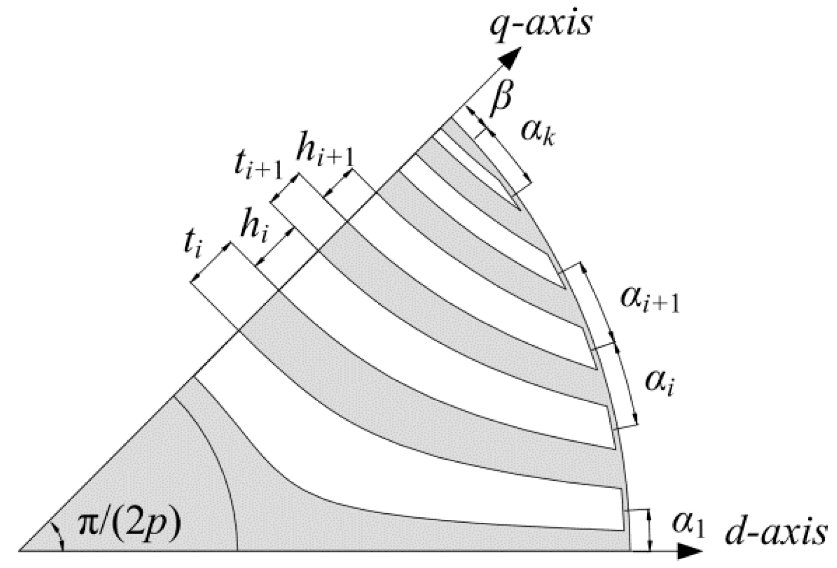
2.2. Rotor Structure of the Proposed Motor

In this paper, the improved rotor with the cross-shaped flux-barriers structure of the SynRM is proposed. The newly added structural parameters are mainly h s e g , i and l a r c i , including l a r c i , 1 and l a r c i , 2 , to represent the decreased thickness of three layers of barriers closed to the shaft, as shown in Figure 2. They are designed to be within eighty percent of the thickness of the barrier layer in which they are located. At the same time, in order to calculate the equivalent reluctance of flux-barrier, each layer of flux-barrier is divided into region I, II and III. It can be seen from Figure 2 that region I and region II exist symmetrically and have equal areas.
To better describe the rotor structure and optimize the flux-barriers structure proposed in the future, two parameters k a r c and k s e g need to be defined, separately:
k a r c = l a r c i , 1 l a r c i , 1 + 2 l a r c i , 2
k s e g = 2 h s e g , i h i
where h s e g , i is the ith layer salient cross-shaped flux-barrier width, l a r c i , 1 ( θ ) and l a r c i , 2 ( θ ) are the lengths of the fluid-shaped flux-barrier after segmentation. k a r c is defined as the ratio of l a r c i , 1 to the total length of the curve, and k s e g is defined as the ratio of h s e g , i to the thickness of the flux-barrier.

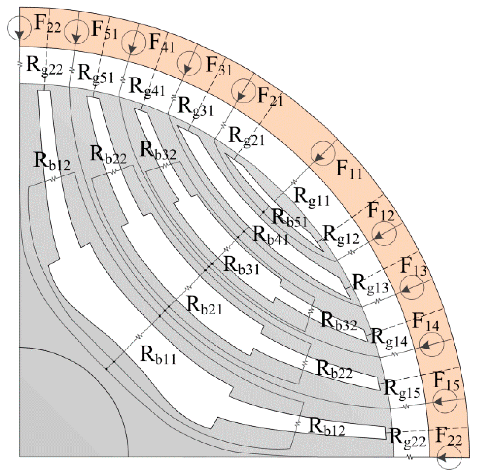
3. Computation of MEC of Proposed Motor

The MEC for the proposed motor is shown in Figure 3. The source of the magnetomotive force and the air-gap reluctance is the same for both models because the stator is the same. The difference between them lies only in the equivalent reluctance of flux-barriers caused by different shapes in the rotor.

3.1. MMF Sources

The function of the overall air-gap MMF field with respect to time and angular position is [13]:
F ( t ,   θ ) = n   =   a ,   b ,   c w n ( θ ) i n ( t )
where n is the phase that n   =   0 ,   1 ,   2 represent the three phases of a, b, and c, respectively, and θ is defined as the angular position measured along the circumference of the average air-gap with the s-axis of phase a as zero reference. Furthermore, w n ( θ ) and i n ( t ) are the winding function of three phases and the current in three phase at instant t , and the specific calculation equation can be referred to [13].
Based on the overall air-gap MMF calculated above, the MMF sources of each region F 1 n and F n 1 in Figure 3 can be calculated.

3.2. Air-Gap Reluctances in the MEC

Since the width of the air-gap is considered to be uniform, air-gap reluctances can be calculated:
R g 1 n = R g n 1 = { ( 1 / μ 0 ) g 2 ( α k + 1 + β ) R L             n = 1 ( 1 / μ 0 ) g α k + 2 n R L                     n = 2 ,   3 ,   ,   k
R g 22 = ( 1 / μ 0 ) g 2 α 1 R L

3.3. Cross-Shaped Flux-Barriers Reluctances
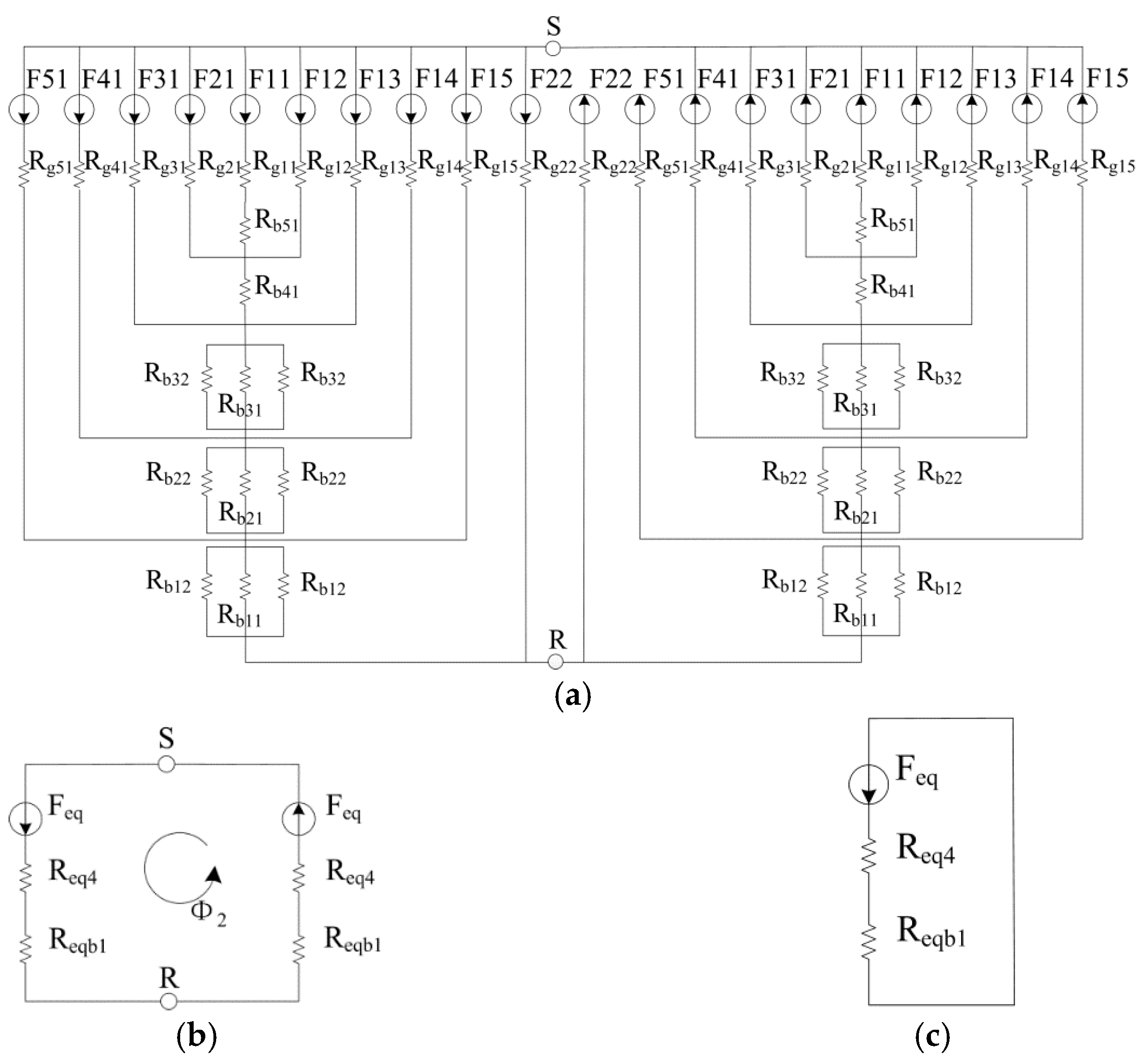
To calculate the reluctance of the improved cross-shaped flux-barriers in the MEC, it is necessary to calculate the length of the curve in the flux-barriers. The calculation equation of curve length is:
l ( θ ) = α β r 2 + ( r ) 2 d θ
Then taking the derivative of r in (1) and substituting the obtained formula with Equation (1) into (7), the calculation equation of curve length is obtained:
l ( θ ) = d α β 8 sin ( 2 θ ) cos 2 ( 2 θ ) [ c + c 2 + 4 sin 2 ( 2 θ ) ] [ c 2 + 4 sin ( 2 θ ) ] + c + c 2 + 4 sin 2 ( 2 θ ) 2 sin 3 ( 2 θ ) 4 cos 2 ( 2 θ ) sin ( 2 θ ) c 2 + 4 sin 2 ( 2 θ ) d θ
The proposed cross-shaped flux-barriers are divided into three parts to calculate the magnetoresistance according to the structural characteristics of the rotor. Since the proposed cross-shaped flux-barriers are symmetric for the q-axis, the reluctance between the two ends of the separated barrier is equal. R b i 1 is the reluctance of the ith layer of the proposed cross-shaped flux-barriers in region I and R b i 2 is the reluctance of the ith layer of the proposed cross-shaped flux-barriers in region II and region III. The reluctances R b i 1 and R b i 2 are defined as, respectively,
R b i 1 = h i + h s e g , i μ 0 l a r c i , 1 ( θ ) L
R b i 2 = h i μ 0 l a r c i , 2 ( θ ) L
where L is the stack length.

3.4. MEC Model

By analyzing the magnetic circuit shown in Figure 4a, the expressions of magnetomotive force and magnetic resistance in the equivalent magnetic circuit shown in Figure 4c can be obtained.
F e q ( t , θ r ) = ( F e q 2 ( t , θ r ) R e q 3 + R e q b 2 + F 15 ( t , θ r ) R g 15 + F 51 ( t , θ r ) R g 51 ) R e q 4 ,
R e q b i = ( R b i 1 1 + 2 R b i 2 1 ) 1                   i = 1 ,   2 ,   3 ,
R e q i = { [ ( R g 11 + R b 51 ) 1 + R g 12 1 + R g 21 1 ] 1 i = 1 [ ( R e q 1 + R b 41 ) 1 + R g 13 1 + R g 31 1 ] 1 i = 2 [ ( R e q 2 + R e q b 3 ) 1 + R g 14 1 + R g 41 1 ] 1 i = 3 [ ( R e q 3 + R e q b 2 ) 1 + R g 15 1 + R g 51 1 ] 1 i = 4 ,
where i represents the number of layers of the flux-barrier, and R e q b i is the equivalent magnetic resistance of R b i 1 in parallel with two R b i 2 . R b i 2 is the equivalent reluctance required for calculation.
By analyzing each magnetic circuit, the equivalent magnetic flux expression of equivalent magnetic circuit can be obtained. Some of the magnetic flux and equivalent magnetic flux through each flux-barrier can be obtained by using Equations (14)–(19).
Φ 2 = F e q ( t ,   θ r ) R e q 4 + R e q b 1
Φ b 51 ( t ,   θ r ) = F 11 ( t ,   θ r ) R g 11 + R b 51 + R b 41 + R e q b 3 + R e q b 2 + R e q b 1
Φ b 41 ( t ,   θ r ) = Φ b 51 ( t ,   θ r ) + F 12 ( t ,   θ r ) R g 12 + R b 41 + R e q b 3 + R e q b 2 + R e q b 1 + F 21 ( t ,   θ r ) R g 21 + R b 41 + R e q b 3 + R e q b 2 + R e q b 1 ,
Φ e q b 3 ( t ,   θ r ) = Φ 41 ( t ,   θ r ) + F 13 ( t ,   θ r ) R g 13 + R e q b 3 + R e q b 2 + R e q b 1 + F 31 ( t ,   θ r ) R g 31 + R e q b 3 + R e q b 2 + R e q b 1 ,
Φ e q b 2 ( t ,   θ r ) = Φ e q b 3 ( t ,   θ r ) + F 14 ( t ,   θ r ) R g 14 + R e q b 2 + R e q b 1 + F 41 ( t ,   θ r ) R g 41 + R e q b 2 + R e q b 1 ,
Φ e q b 1 ( t ,   θ r ) = Φ e q b 2 ( t ,   θ r ) + F 15 ( t ,   θ r ) R g 15 + R e q b 1 + F 51 ( t ,   θ r ) R g 51 + R e q b 1 .
When the equivalent magnetic flux and equivalent magnetic resistance are calculated, the expression of three-layer magnetomotive force drop can be further obtained.
Δ F e q b i ( t ,   θ r ) = Φ e q b i ( t ,   θ r ) R e q b i             i = 1 , 2 , 3 ,
Δ F b i 1 ( t ,   θ r ) = Φ b i 1 ( t ,   θ r ) R b i 1             i = 4 , 5 .
The expressions of magnetic flux in different regions are as follows:
Φ b i 1 ( t ,   θ r ) = Δ F e q b i ( t ,   θ r ) R b i 1             i = 1 , 2 , 3 ,
Φ b i 2 ( t ,   θ r ) = Δ F e q b i ( t ,   θ r ) R b i 2             i = 1 , 2 , 3 .

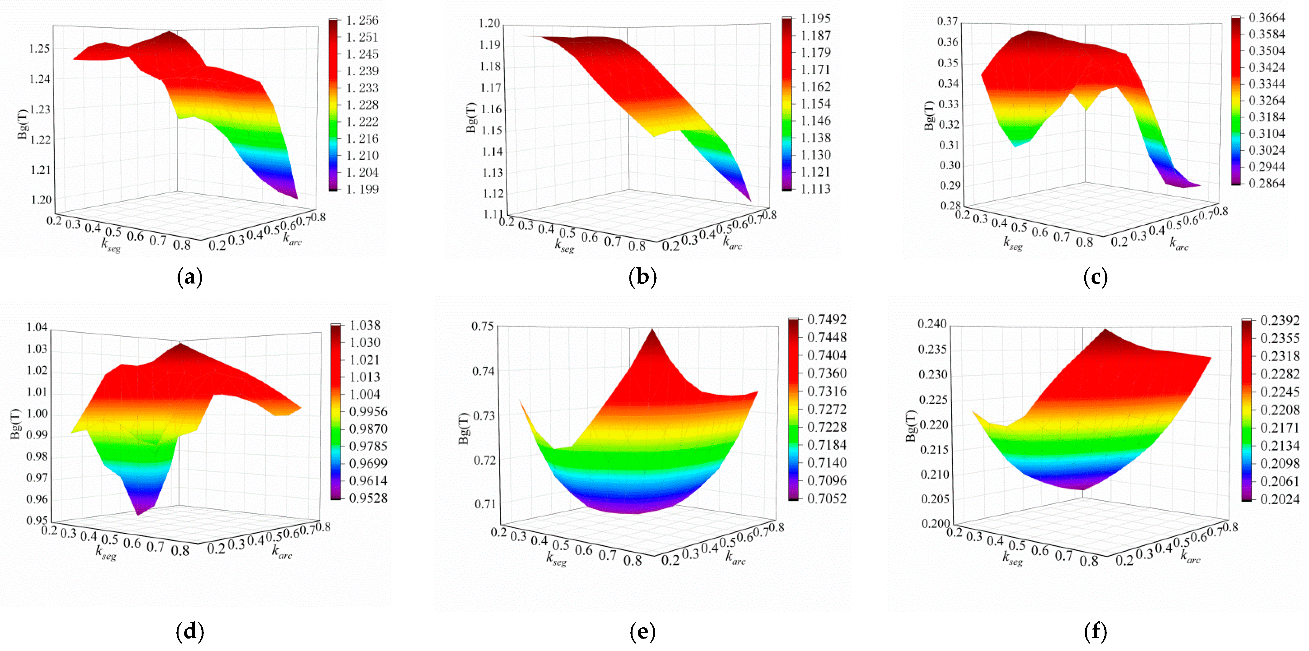
3.5. Air-Gap Flux Density

The MMF drops of the flux-barriers are independent of the path of the magnetic field line through the barriers [21]. Therefore, the air-gap flux density at different locations can be calculated according to the following method proposed in this paper, and the partition diagram of air-gap between stator and rotor are shown in Figure 5.
1.
When the magnetic field line passes through all flux-barriers and comes out of region 11, the flux density is expressed as,
B g ( t ,   θ p   , θ r ) = μ 0 g [ F ( t ,   θ p ) Δ F b 51 ( t ,   θ p ) Δ F b 41 ( t ,   θ p ) i = 1 n Δ F e q b i ( t ,   θ r ) ] ,
where, θ r θ p θ r + ( β + α 6 ) p or θ r + 2 π ( β + α 6 ) p θ p θ r + 2 π ;
B g ( t ,   θ p   , θ r ) = μ 0 g [ F ( t ,   θ p ) + Δ F b 51 ( t ,   θ p ) + Δ F b 41 ( t ,   θ p ) + i = 1 n Δ F e q b i ( t ,   θ r ) ] ,
where θ r ( β + α 6 ) p + π θ p θ r + ( β + α 6 ) p + π ;
2.
When the magnetic field line only does not passes through the outermost magnetic barriers, that is, through the first four layers of magnetic barrier, and comes out of region 12 or region 21, the magnetic density is expressed as,
B g ( t ,   θ p   , θ r ) = μ 0 g [ F ( t ,   θ p ) Δ F b 41 ( t ,   θ p ) i = 1 n Δ F e q b i ( t ,   θ r ) ] ,
where, θ r + ( β + α 6 ) p θ p θ r + ( β + α 6 + α 5 ) p or θ r + 2 π ( β + α 6 + α 5 ) p θ p θ r + 2 π ( β + α 6 ) p ;
B g ( t ,   θ p   , θ r ) = μ 0 g [ F ( t ,   θ p ) + Δ F b 41 ( t ,   θ p ) + i = 1 n Δ F e q b i ( t ,   θ r ) ] ,
where, θ r ( β + α 6 + α 5 ) p + π θ p θ r ( β + α 6 ) p + π or θ r + ( β + α 6 ) p + π θ p θ r + ( β + α 6 + α 5 ) p + π ;
3.
When the magnetic field line passes through the first three magnetic barriers, and comes out of region 13 or region 31, the magnetic density is expressed as,
B g ( t ,   θ p   , θ r ) = μ 0 g [ F ( t ,   θ p ) i = 1 n Δ F e q b i ( t ,   θ r ) ] ,
where, θ r + ( β + α 6 + α 5 ) p θ p θ r + ( β + α 6 + α 5 + α 4 ) p or θ r + 2 π ( β + α 6 + α 5 + α 4 ) p θ p θ r + 2 π ( β + α 6 + α 5 ) p ;
B g ( t ,   θ p   , θ r ) = μ 0 g [ F ( t ,   θ p ) + i = 1 n Δ F e q b i ( t ,   θ r ) ] ,
where, θ r ( β + α 6 + α 5 + α 4 ) p + π θ p θ r ( β + α 6 + α 5 ) p + π or θ r + ( β + α 6 + α 5 ) p + π θ p θ r + ( β + α 6 + α 5 + α 4 ) p + π ;
4.
When the magnetic field line passes through the first and the second magnetic barriers, and comes out of region 14 or region 41, the magnetic density is expressed as,
B g ( t ,   θ p   , θ r ) = μ 0 g [ F ( t ,   θ p ) Δ F e q b 2 ( t ,   θ r ) Δ F e q b 1 ( t ,   θ r ) ] ,
where, θ r + ( β + α 6 + α 5 + α 4 ) p θ p θ r + π / 2 ( α 1 + α 2 ) p or θ r + 3 π / 2 + ( α 1 + α 2 ) p θ p θ r + 3 π / 2 + ( α 1 + α 2 + α 3 ) p ;
B g ( t ,   θ p   , θ r ) = μ 0 g [ F ( t ,   θ p ) + Δ F e q b 2 ( t ,   θ r ) + Δ F e q b 1 ( t ,   θ r ) ] ,
where, θ r + π / 2 + ( α 1 + α 2 ) p θ p θ r + π / 2 + ( α 1 + α 2 + α 3 ) p or θ r + 3 π / 2 ( α 1 + α 2 + α 3 ) p θ p θ r + 3 π / 2 ( α 1 + α 2 ) p ;
5.
When the magnetic field line only passes through the innermost flux-barrier, and comes out of region 15 or region 51, the magnetic density is expressed as,
B g ( t ,   θ p   , θ r ) = μ 0 g [ F ( t ,   θ p ) Δ F e q b 1 ( t ,   θ r ) ] ,
where, θ r π / 2 ( α 1 + α 2 ) p θ p θ r + π / 2 α 1 p or θ r + 3 π / 2 + α 1 p θ p θ r + 3 π / 2 + ( α 1 + α 2 ) p ;
B g ( t ,   θ p   , θ r ) = μ 0 g [ F ( t ,   θ p ) + Δ F e q b 1 ( t ,   θ r ) ] ,
where, θ r π / 2 + α 1 p θ p θ r + π / 2 + ( α 1 + α 2 ) p or θ r + 3 π / 2 ( α 1 + α 2 ) p θ p θ r + 3 π / 2 α 1 p ;
6.
When the magnetic field line does not pass through any flux-barrier and comes out of region 22, the magnetic density is expressed as,
B g ( t ,   θ p   , θ r ) = μ 0 g F ( t ,   θ p ) ,
where, θ r + π / 2 α 1 p θ p θ r + π / 2 + α 1 p or θ r + 3 π / 2 α 1 p θ p θ r + 3 π / 2 + α 1 p .
As can be seen from the above analysis, the distribution of air-gap flux density is related to the MMF sources of each region, the air-gap reluctances, and the reluctances of the proposed cross-shaped flux-barriers that appear in the MEC. If the partition remains unchanged, it can be seen that the distribution of air-gap flux density is related to the reluctances of the proposed cross-shaped flux-barriers, that is, to the structural parameters of the cross-shaped flux-barriers.

3.6. Torque and Performance Evaluation Index

The electromagnetic torque T can be calculated by the total magnetic energy stored in the motor without considering the magnetic saturation, and the calculation equation is,
T ( t ,   θ r ) = W m ( t ,   θ r ) θ r ,
where W m is the total magnetic energy stored by the proposed rotor with cross-shaped flux-barriers structure of SynRM.
The assumption is made that the magnetic permeability of the core is much greater than that of the air, that is, the core does not store magnetic energy, the total magnetic energy stored in the motor can be divided into two parts, one is the magnetic energy stored in the magnetic barrier W m b , the other is the magnetic energy stored in the air-gap W m g . Then the total magnetic energy W m can be expressed by the following equation:
W m ( t ,   θ r ) = W m b ( t ,   θ r ) + W m g ( t ,   θ r ) .
The magnetic energy stored in the magnetic barrier W m b is expressed as,
W m b ( t ,   θ r ) = p [ R b 51 Φ b 51 ( t ,   θ r ) 2 + R b 41 Φ b 41 ( t ,   θ r ) 2 + R e q b 3 Φ e q b 3 ( t ,   θ r ) 2 + R e q b 2 Φ e q b 2 ( t ,   θ r ) 2 + R e q b 1 Φ 2 ( t ,   θ r ) 2 ] .
The magnetic energy stored in the air-gap W m g is expressed as,
W m g ( t ,   θ r ) = L ( D r g ) g 4 μ 0 0 2 π B g ( t , θ , θ r ) 2 d θ .
Through the above steps, the torque of the proposed SynRM with cross-shaped fluid-berriers can be predicted. Next the torque ripple Δ T is defined as the ratio of the difference between the maximum value of torque T max and the minimum value of torque T min to the average value of torque T a v g :
Δ T = T max T min T a v g .
The sensitivity [14] is also used in this paper as one of the indicators to evaluate the performance of the motor. The method can be exploited when a discrete representation of the research domain is available [29]. Firstly, a perturbation space of n v -dimensional hypercube with design vector in the center is established to estimate the maximum rate of change of torque pulsation, and the dimension of the parameter space is equal to the number of parameters, which is two in this paper. The parameters of the geometry in a generic solution are defined by the vector f = ( f 1 , f 2 , , f n ) , where f 1 = k a r c and f 2 = k s e g , and both values range from 0 to 0.8 in this study. The distance between the vector f and the vector f is calculated by the following equation:
d ( f , f ) = [ i = 1 n v ( f i f i ) 2 ] 1 2 .
Sensitivity analysis of solutions in space requires the determination of a radius of an hypersphere R, which must be adequately small to properly assess the sensitivity of each solution, but also adequately large to find other solutions around each one [30]. The number of solutions in this study is 65, and R is 0.2 after comprehensive consideration.
For the solution with the minimum torque ripple, the parameters of the geometry is defined by the vector f ˜ = ( f ˜ 1 , f ˜ 2 , , f ˜ n ) , and then the fluctuation of the torque ripple is computed according to the variation of the geometry with respect to the optimal solution f ˜ , so as to evaluate the rate of change of the ripple with the deviation from the optimal solution f ˜ . The distance of a generic solution f from the f ˜ is:
d ( f , f ˜ ) = [ i = 1 n v ( f i f ˜ i ) 2 ] 1 2 .
Maximum and minimum torque ripple can be obtained by comparing all solutions in the hypercube which is centered in the solution f . The sensitivity of torque ripple at f is defined as:
s ( f ) = Δ T max Δ T min Δ T ( f ) .

4. Analysis and Comparison of Air-Gap Flux Density and Torque Performance

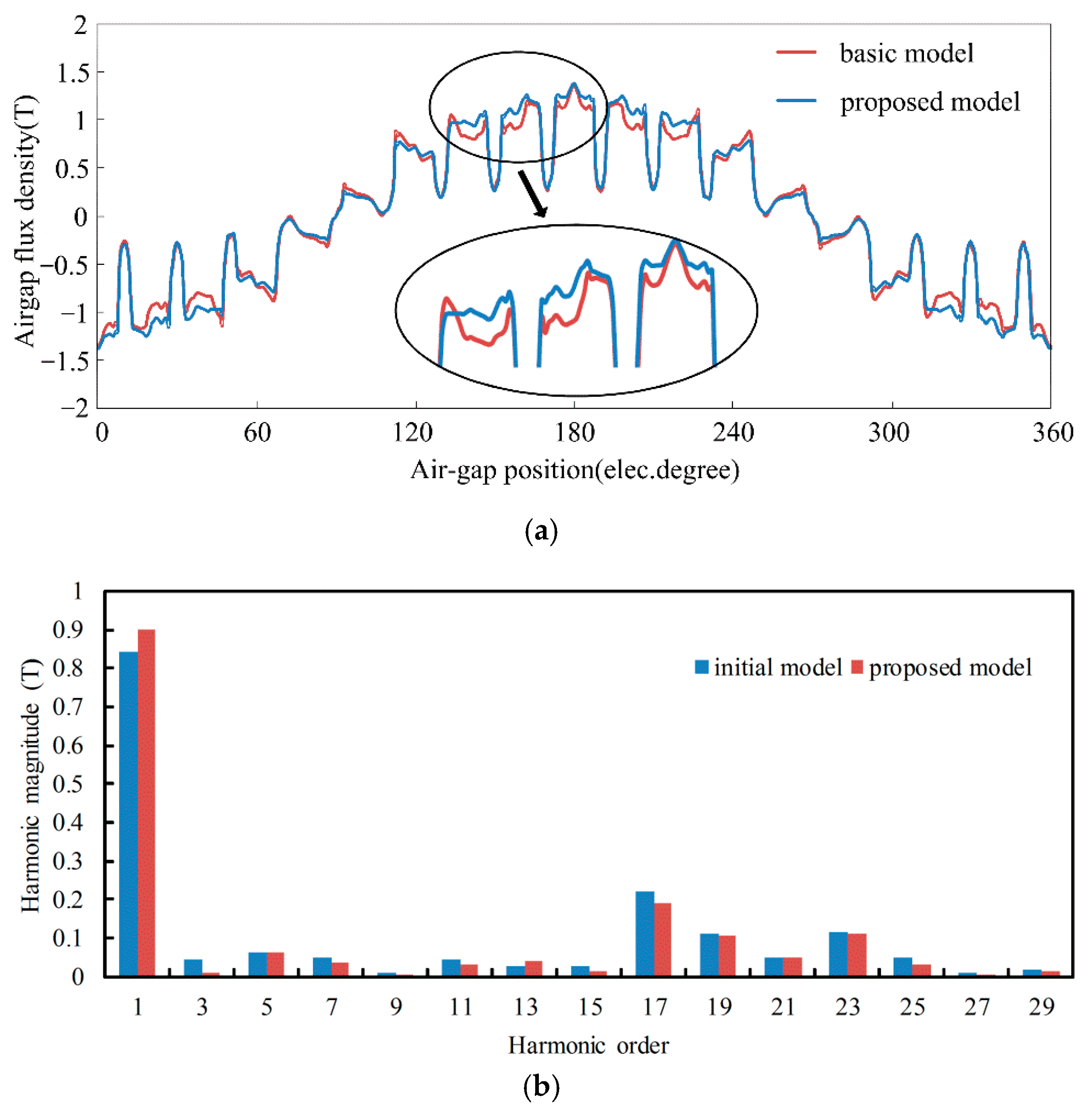
4.1. Distribution of Air-Gap Flux Density

To further study the influence of cross-shaped flux-barriers on the distribution of air-gap flux density, the air-gap between stator and rotor in one-eighth motor model was divided more accurately from the original six regions to obtain 16 regions, as shown in Figure 6, which were mainly divided according to the width of the flux-barriers end. These 16 regions can be divided into three parts for research: one is the region A1–A6 corresponding to the segments, and the other is the region B1–B5 and C1–C5 corresponding to the end of the flux-barriers.
The influence of the structural parameters of the cross-shaped flux-barriers on the air-gap flux density is studied by finite element analysis at rated current 21.79 A and rated speed 1500 rpm. The finite element results are shown in Figure 7, Figure 8 and Figure 9. Among them, the flux density of each region is analyzed by taking the value at the geometric midpoint of each region.
Figure 7 shows the influence of parameters of cross-shaped flux-barriers on the air-gap flux density of region A1–A6 which are mainly located in the corresponding air gap at the end of the segment of the rotor. It can be seen that when the parameter k s e g remains unchanged, the value of flux density of region A1, A2 and A3 all remain unchanged first and then decrease with the increase of k a r c . When k a r c is constant, the value of flux density decreases with the increase of k a r c for regions A1 and A2, while the value of flux density increases first and then decreases with the increase of k a r c for region A3. Furthermore, the value of flux density decreases to the minimum when k s e g = k a r c = 0.8 for all three regions. The variation trend of A5 and A6 are basically the same as each other when one parameter of k s e g and k a r c remains unchanged. The value of flux density decreases first and then increases with the change of the other parameter. The change of flux density value in region A4 is different from the above regions while the cross-shaped flux-barrier parameters change, which is approximately funnel-shaped, and the value of flux density is the minimum when k s e g = k a r c = 0.4 . The main reason is that the change of value k a r c and k s e g changes the equivalent reluctance of the flux-barriers in MEC, which leads to the corresponding change of the value of flux-density of the air-gap at different positions.
Figure 8 shows the influence of parameters of cross-shaped flux-barriers on the air-gap flux density of region B1–B5 which are mainly located in the air gap corresponding to the upper half of the end of the flux barriers. It can be seen from Figure 8b,c that the cross-shaped flux-barrier parameters have the same influence on regions B2 and B3. That is, when k s e g is fixed, the value of flux density increases with the increase of k a r c , while the value of flux density has little change with k s e g when k a r c is fixed. When one parameter is fixed, the value of flux density increases first and then decreases with the increase of the other parameter. k s e g and k a r c have slightly different effects on region B4 because it can be seen that when k a r c is constant, the value of flux density decreases with the increase of k s e g . In contrast, the value of flux density increases with the increase of k a r c when k s e g is small and remains unchanged when k s e g is large. It can be seen from the observation of Figure 8e that cross-shaped flux-barrier parameters exert a similar influence on the value of flux density on region B5 to region A5.
Figure 9 shows the influence of parameters of cross-shaped flux-barriers on the air-gap flux density of region C1–C5 which are mainly located in the air gap corresponding to the lower half of the end of the flux barriers. As can be seen from the figure, the impact of k s e g and k a r c on regions C2 and C3 is consistent with that of regions B2 and B3 analyzed above, and the same tendency with the region C4 and C5 with that of region B4. When one of the two variables k s e g and k a r c is fixed, and the other one increases, the value of flux density shows a changing trend of increasing first and then decreasing, thus forming an umbrella-shaped trend as shown in Figure 10c. Moreover, the flux density reaches its maximum value when k s e g = k a r c = 0.4 .
It can be observed from the Figure 7, Figure 8 and Figure 9 that the magnetic density value of each region is affected by the change of equivalent reluctance of flux barriers, and some of the changes are nonlinear.

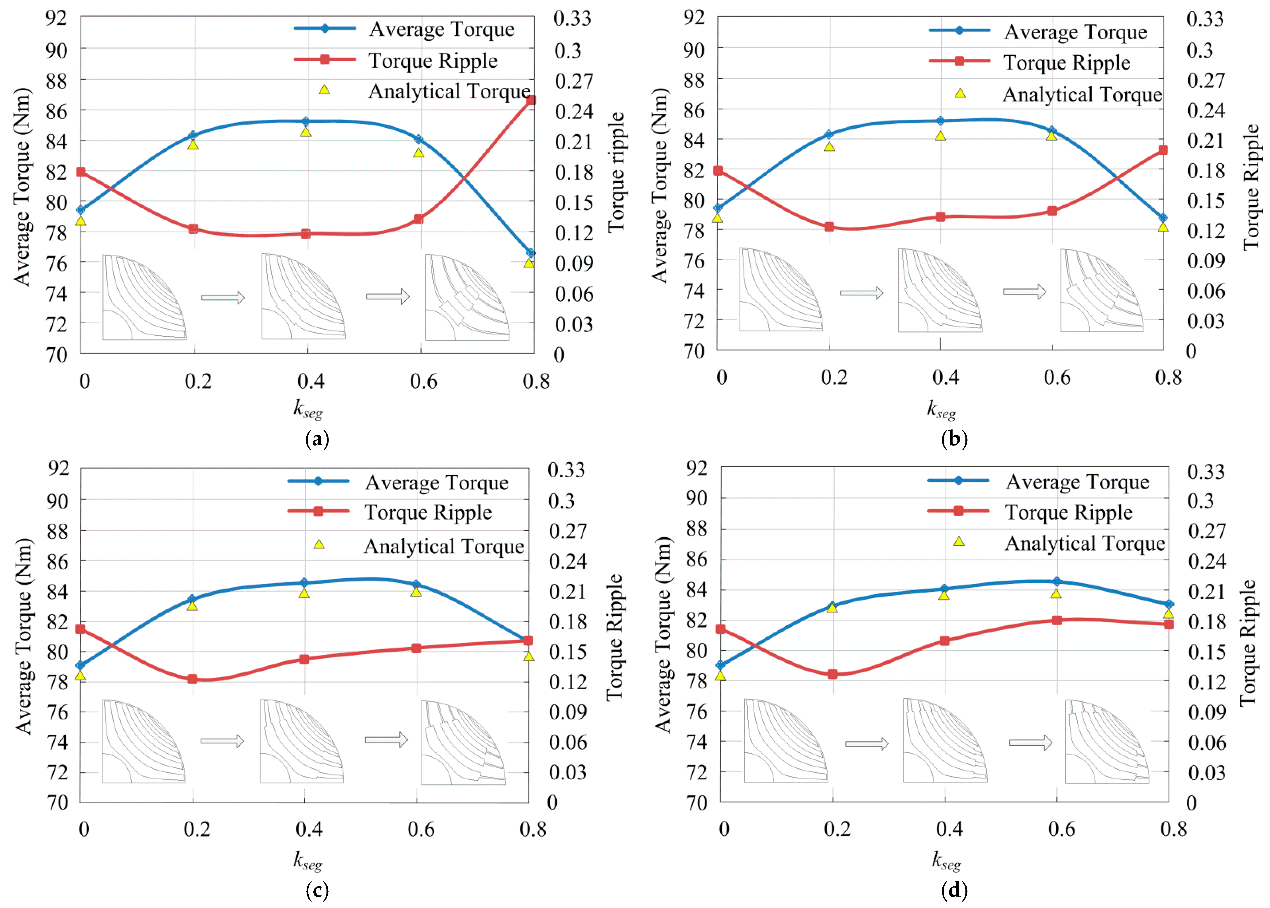
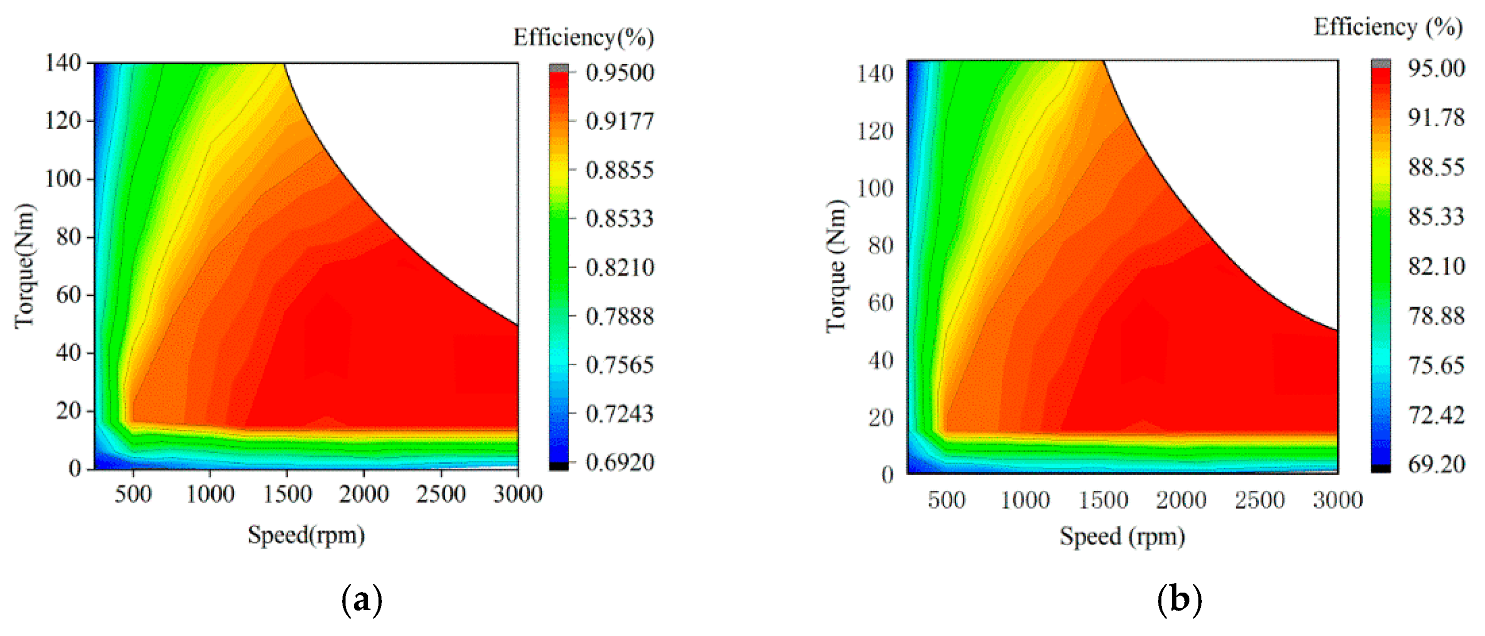
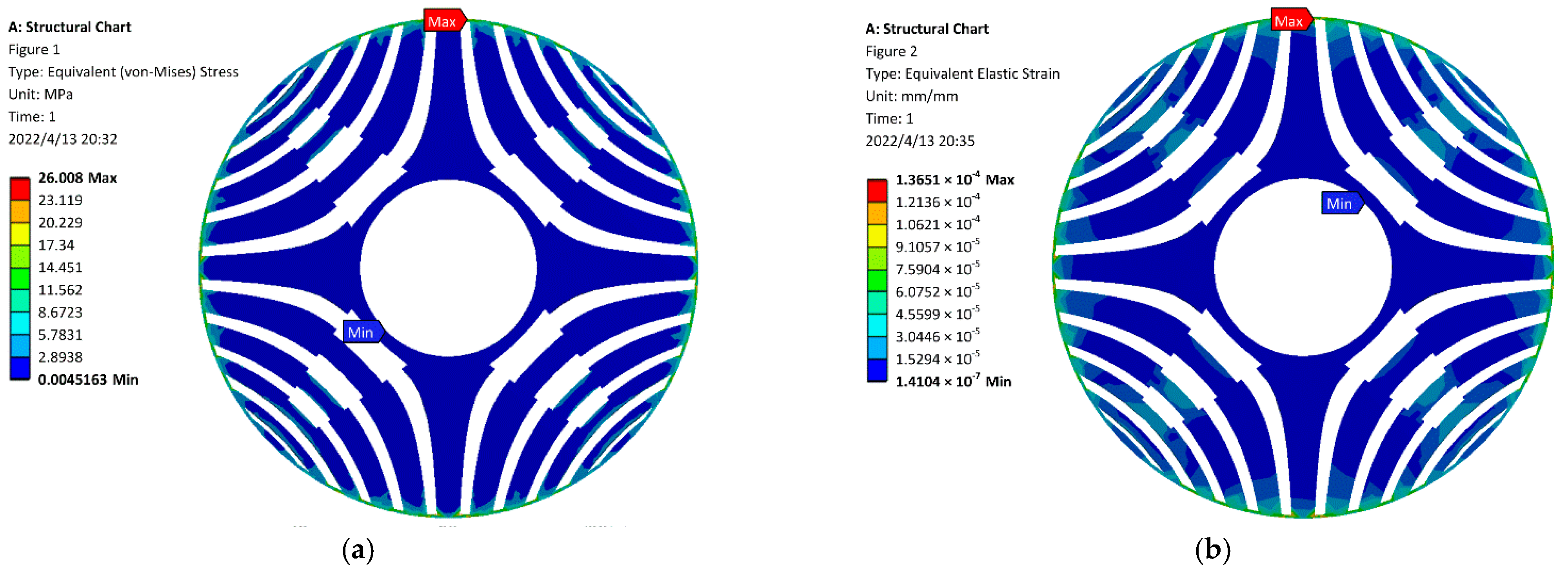
4.2. Analysis of Torque Performance

The torque reflects the output capacity of the motor, and the torque ripple demonstrates the stability of the output of the motor, which are two crucial indicators of electromagnetic performance. When the values of k a r c and k s e g are different, that is, the flux- barrier structure changes, the torque value of the motor with the corresponding rotor structure can be calculated according to the MEC of proposed motor established in Section 3.
The analytical torque is compared with the result of FEA simulation, as show in Figure 10. The stator current are set with I 0 = 21.79   A and T = 20   ms (the frequency is 50 Hz). It can be seen from the figure that the analytical torque is basically consistent with the simulation results, which verifies the validity of the model and can be used for torque prediction in the early stage of motor rotor structure design. The influence of k s e g and k a r c on average torque and torque ripple can also be seen in Figure 10. It can be found that when k a r c is fixed, the average torque first increases and then decreases with the increase of k s e g , while the torque ripple shows an opposite trend. Furthermore, average torque is hardly changed when k a r c remains constant, and k s e g varies between 0.2 and 0.6. When the overall trend of air-gap flux-density is closer to sinusoidal, the torque ripple will be smaller. According to Equations (35)–(38), the energy in the magnetic circuit will also change correspondingly when the magnetic barrier structure changes, which is finally reflected in the change of torque.
Based on the above analysis, the structural parameters of SynRM with cross-shaped flux-barriers rotor structure with relatively better torque performance can be obtained as k s e g = 0.4 and k a r c = 0.2 . At this point, the average torque of the motor is 85.26 Nm, and the torque ripple is 11.79%.
In order to verify the effectiveness of the method, the same optimization was carried out for motors with three layers and four layers flux-barrier structures, respectively, as shown in the Figure 11. It can be found that for a SynRM with three layers of flux barrier, the torque can be increased from 75.2 Nm to 82.15 Nm by using the proposed method, and the torque ripple is reduced by 27.69%. For a SynRM with four layers of flux barrier, it is necessary to make a trade-off between the two performance indexes of torque and torque ripple. However, no matter how to choose, the motor with better performance than the initial motor can be obtained. Therefore, it can be proved that the proposed method is not only suitable for the motor with five layers of flux barrier structure, but also has universality.

4.3. Comparison of Air-Gap Flux Density and Torque Performance

The 3D view of the rotor of initial motor (left) and proposed motor (right) are showed in Figure 12a. Figure 12b shows the comparison of torque waveform between the initial motor and the proposed motor with the cross-shaped flux-barriers rotor. The torque ripple decreases by 34.06%, and the average torque increases by 11.34% with the comparison of the initial motor. Figure 12c highlights that the shaped of flux-barriers affects the intent of torque harmonic the proposed rotor structure with cross-shaped flux-barriers with low torque ripple has lower torque harmonics.
Figure 13 shows the contrast diagram of air-gap flux density distribution and harmonic content of no-load motor at rated current. Figure 13a reflects the existence of stator slot and rotor anisotropy, and it can be seen from Figure 13b that there are odd harmonics in addition to the fundamental components. The third and its multiple harmonics are primarily caused by magnetic saturation, and the 17th and 19th harmonics are primarily related to stator slotting, and the 11th, 13th, 23rd, 25th and 29th harmonics are mainly caused by rotor structure. As for the two motors in this paper, the harmonic components vary with the shape of the flux barrier in the rotor. It can be seen from the Figure that the amplitude of the fundamental wave of the air-gap flux density of the proposed SynRM with cross-shaped flux-barriers rotor structure is higher than that of the initial SynRM, and the majority contents of harmonics are reduced, which makes the air-gap flux density distribution more sinusoidal and leads to reduced torque ripple.
Figure 14 is the flux line distribution of the initial motor and the proposed motor in steady state. As can be seen that the trend of flux lines is basically the same as the shape of flux barrier, and the flux lines are symmetrically distributed. Most of the flux lines of the two motors go along the segment, and only a few of them pass through the flux barrier, that is, to ensure the inductance of d-axis is maximum and the inductance of q-axis is minimum.
Table 2 show the output characteristics of initial model and proposed motor. As can be seen from the table, the performance of the proposed motor is better than that of the first motor, with lower core loss and stranded loss and higher efficiency. At the same time, the sensitivity of the proposed motor is lower than that of the initial motor, which verifies the feasibility of the proposed method.
Figure 15 shows the efficiency map of initial motor and proposed motor. The rated speed is 1500 rpm. In order to ensure that the voltage is not higher than the rated voltage, it is necessary to reduce the current or change the current angle thus reducing the torque when the speed exceeds 1500 rpm. In the constant torque region, the efficiency of both can reach 88%, and in the constant power region can reach 94%.
When considering magnetic structure design, mechanical strength is also a point to pay attention to. Therefore, the rotor stress of motor running at 1.5 times rated speed is analyzed. As can be seen from Figure 16 the maximum stress point of the motor is located at the end of the flux barrier of the first layer (near the shaft), and the stress is 26.008 MPa, which is far lower than the required pressure of 340 MPa for the silicon steel sheet. Furthermore, the deformation at this time is only 1.3651 × 10⁻⁴ mm, which is a minimal value for the rotor. The mechanical stability of the motor can be guaranteed under normal operation.
The main application field of the low-speed synchronous reluctance motor studied in this paper is the textile industry and conveyor belt, so the performance requirements are up to standard, and the design method proposed is feasible.

5. Conclusions

In this paper, an improved rotor structure of synchronous reluctance motor with cross-shaped flux-barriers is proposed to improve the torque performance of the motor. A method for magnetic field analysis of synchronous reluctance motor with cross-shaped flux-barriers rotor structure is proposed. The structure of cross-shaped flux barrier is mainly determined by two design parameters. By designing the structure parameters of the magnetic barrier reasonably and calculating the equivalent magnetic resistance of the proposed cross magnetic barrier, the rotor magnetic circuit was analyzed by MEC, and the air-gap flux density and torque characteristics of the cross-shaped flux-barrier distribution of the improved synchronous reluctance motor were predicted, and the results are compared with the finite element analysis. The results show that the proposed rotor structure with cross-shaped flux-barriers can reduce the harmonic content and make the air-gap flux-density more sinusoidal, thus reducing the torque ripple. Compared with the initial model, the torque ripple can be reduced by 34.06% and the average torque can be increased by 11.34% by designing the parameters of the crossed flux separator reasonably.

Author Contributions

Conceptualization, J.L. and Y.D. and H.S.; methodology, J.L.; formal analysis, J.L.; investigation, J.L., R.L. and G.Z.; data curation, J.L. and R.L.; writing—original draft preparation, J.L.; writing—review and editing, J.L. and Y.D.; supervision, Y.D. and H.S.; project administration, Y.D.; funding acquisition, Y.D. All authors have read and agreed to the published version of the manuscript.

Funding

This research was funded by the National Natural Science Foundation of China, grant number U20A201284.

Institutional Review Board Statement

Not applicable.

Informed Consent Statement

Not applicable.

Data Availability Statement

The datasets generated and/or analyzed during the current study are not publicly available due to the requirement of the security but are available from the corresponding author on reasonable request.

Conflicts of Interest

The authors declare no conflict of interest.

References

  1. Okamoto, Y.; Yamashita, Y. Design Optimization of Synchronous Reluctance Motor for Reducing Iron Loss and Improving Torque Characteristics Using Topology Optimization Based on Level-set Method. IEEE Trans. Magn. 2020, 56, 1–4. [Google Scholar]
  2. Kim, S.; You, Y. Optimization of a Permanent Magnet Synchronous Motor for e-Mobility Using Metamodels. Appl. Sci. 2022, 12, 1625. [Google Scholar] [CrossRef]
  3. Liu, C.T.; Shih, P.C.; Cai, Z.H.; Yen, S.C.; Lin, S.Y. Rotor Conductor Arrangement Designs of High-Efficiency Direct-on-Line Synchronous Reluctance Motors for Metal Industry Applications. IEEE Trans. Ind. Appl. 2020, 56, 4337–4344. [Google Scholar]
  4. Islam, M.Z.; Choi, S.; Elbuluk, M.E.; Bonthu, S.S.R.; Arafat, A.; Baek, J. Design of External Rotor Ferrite-Assisted Synchronous Reluctance Motor for High Power Density. Appl. Sci. 2021, 11, 3102. [Google Scholar] [CrossRef]
  5. Murataliyev, M.; Degano, M.; Galea, M. A Novel Sizing Approach for Synchronous Reluctance Machines. IEEE Trans. Ind. Electron. 2021, 68, 2083–2095. [Google Scholar] [CrossRef]
  6. Giacomo, B.; Nicola, B.; Hanafy, M. A Nonlinear Analytical Model for the Rapid Prediction of the Torque of Synchronous Reluctance Machines. IEEE Trans. Energy Convers. 2018, 33, 1539–1546. [Google Scholar]
  7. Mohammadi, M.H.; Rahman, T.; Silva, R.; Li, M.; Lowther, D.A. A Computationally Efficient Algorithm for Rotor Design Optimization of Synchronous Reluctance Machines. IEEE Trans. Magn. 2016, 52, 1–4. [Google Scholar] [CrossRef]
  8. Mirazimi, M.S.; Kiyoumarsi, A. Magnetic Field Analysis of SynRel and PMASynRel Machines with Hyperbolic Flux Barriers Using Conformal Mapping. IEEE Trans. Transp. Electrif. 2020, 6, 52–61. [Google Scholar] [CrossRef]
  9. Kabir, M.A.; Husain, I. Application of a Multilayer AC Winding to Design Synchronous Reluctance Motors. IEEE Trans. Ind. Appl. 2018, 54, 5941–5953. [Google Scholar] [CrossRef]
  10. Tawfiq, K.B.; Ibrahim, M.N.; EI-Kholy, E.E.; Sergeant, P. Performance Improvement of Synchronous Reluctance Machines—A Review Research. IEEE Trans. Magn. 2021, 57, 1–11. [Google Scholar] [CrossRef]
  11. Yu, H.; Yu, G.; Xu, Y.; Zou, J. Torque Performance Improvement for Slotted Limited-Angle Torque Motors by Combined SMA Application and GA Optimization. IEEE Trans. Magn. 2021, 57, 1–5. [Google Scholar] [CrossRef]
  12. Yan, D.; Xia, C.; Guo, L.; Wang, H.; Shi, T. Design and Analysis for Torque Ripple Reduction in Synchronous Reluctance Machine. IEEE Trans. Magn. 2018, 54, 1–5. [Google Scholar]
  13. Tessarolo, A. Modeling and Analysis of Synchronous Reluctance Machines with Circular Flux-barriers through Conformal Mapping. IEEE Trans. Magn. 2015, 51, 1–11. [Google Scholar] [CrossRef]
  14. Bianchi, N.; Degano, M.; Fornasiero, E. Sensitivity analysis of torque ripple reduction of Synchronous Reluctance and Interior PM Motors. IEEE Trans. Ind. Appl. 2014, 51, 187–195. [Google Scholar] [CrossRef]
  15. Ban, B.; Stipetic, S.; Jercic, T. Minimum Set of Rotor Parameters for Synchronous Reluctance Machine and Improved Optimization Convergence via Forced Rotor Barrier Feasibility. Energies. 2021, 14, 2744. [Google Scholar] [CrossRef]
  16. Vagati, A.; Pastorelli, M.; Franceschini, G.; Petrache, S.C. Design of low-torque-ripple synchronous reluctance motors. IEEE Trans. Ind. Appl. 1998, 34, 758–765. [Google Scholar] [CrossRef]
  17. Murataliyev, M.; Degano, M.; Nardo, M.D.; Bianchi, N.; Tessarolo, A.; Jara, W.; Galea, M.; Gerada, C. Homothetic Design in Synchronous Reluctance Machines and Effects on Torque Ripple. IEEE Trans. Energy Convers. 2021, 36, 2195–2205. [Google Scholar] [CrossRef]
  18. Chen, Q.; Yan, Y.; Xu, G.; Xu, M.; Liu, G. Principle of Torque Ripple Reduction in Synchronous Reluctance Motors with Shifted Asymmetrical Poles. IEEE Trans. Emerg. Sel. Topics Power Electron. 2020, 8, 2611–2622. [Google Scholar] [CrossRef]
  19. Pellegrino, G.; Cupertino, F.; Gerada, C. Automatic Design of Synchronous Reluctance Motors Focusing on Barrier Shape Optimization. IEEE Trans. Ind. Appl. 2015, 51, 1465–1474. [Google Scholar] [CrossRef]
  20. Bacco, G.; Bianchi, N. Design Criteria of Flux-Barriers in Synchronous Reluctance Machines. IEEE Trans. Ind. Appl. 2019, 55, 2490–2498. [Google Scholar] [CrossRef]
  21. Bianchi, N.; Bolognani, S.; Bon, D.; Pre, M.D. Torque Harmonic Compensation in a Synchronous Reluctance Motor. IEEE Trans. Energy Convers. 2008, 23, 466–473. [Google Scholar] [CrossRef]
  22. Wang, K.; Zhu, Z.; Ombachg, G.; Koch, M.; Zhang, S. Torque ripple reduction of synchronous reluctance machines: Using asymmetric flux-barrier. Compel Int. J. Comput. Math. Eletr. Electron. Eng. 2015, 34, 18–31. [Google Scholar] [CrossRef]
  23. Pellegrino, G.; Cupertino, F.; Gerada, C. Barriers shapes and minimum set of rotor parameters in the automated design of synchronous reluctance machines. In Proceedings of the 2013 International Electric Machines Drives Conference(IEMDC), Chicago, IL, USA, 12–15 May 2013; pp. 899–904. [Google Scholar]
  24. Gamba, M.; Pellegrino, G.; Cupertino, F. Optimal number of rotor parameters for the automatic design of Synchronous Reluctance machines. In Proceedings of the 2014 International Conference on Electrical Machines (ICEM), Berlin, Germany, 2–5 September 2014; pp. 1334–1340. [Google Scholar]
  25. Bacco, G.; Bianchi, N. Choice of flux-barriers position in synchronous reluctance machines. In Proceedings of the 2017 IEEE Energy Conversion Congress and Exposition (ECCE), Cincinnati, OH, USA, 1–5 October 2017; pp. 1872–1879. [Google Scholar]
  26. Bianchi, N. Synchronous Reluctance and PM Assisted Reluctance Motors. In The Rediscovery of Synchronous Reluctance and Ferrite Permanent Magnet Motors—Tutorial Course Notes; Springer International Publishing AG: Cham, Switzerland, 2016; pp. 27–57. [Google Scholar]
  27. Zhu, L.; Jiang, S.Z.; Zhu, Z.Q.; Chan, C.C. Analytical Methods for Minimizing Cogging Torque in Permanent-Magnet Machines. IEEE Trans. Magn. 2009, 45, 2023–2031. [Google Scholar] [CrossRef]
  28. Ferrari, S.; Pellegrino, G. FEAfix: FEA Refinement of Design Equations for Synchronous Reluctance Machines. IEEE Trans. Ind. Appl. 2020, 56, 256–266. [Google Scholar] [CrossRef]
  29. Barba, P.D. Multiobjective Shape Design in Electricity and Magnetism; Springer: New York, NY, USA, 2010; pp. 147–155. [Google Scholar]
  30. Babetto, C.; Bacco, G.; Bianchi, N. Synchronous Reluctance Machine Optimization for High-Speed Applications. IEEE Trans. Energy Convers. 2018, 33, 1266–1273. [Google Scholar] [CrossRef]
Figure 1. Rotor structure and design variables of the initial motor.
Applsci 12 03958 g001
Figure 2. Proposed rotor structure and design variables.
Applsci 12 03958 g002
Figure 3. MEC for a SynRM with cross-shaped flux-barriers.
Applsci 12 03958 g003
Figure 4. (a) MEC for the proposed motor; (b) Simplified equivalent circuits of (a); (c) Final simplified equivalent circuits of SynRM with proposed rotor structure MEC for a SynRM with cross-shaped flux-barriers.
Applsci 12 03958 g004
Figure 5. Partition diagram of air-gap between stator and rotor.
Applsci 12 03958 g005
Figure 6. Detailed partition diagram of air-gap between stator and rotor of one-eighth motor.
Applsci 12 03958 g006
Figure 7. The influence of cross-shaped flux-barriers parameters on flux density in each region of air-gap: (a) region A1; (b) region A2; (c) region A3; (d) region A4; (e) region A5; (f) region A6.
Applsci 12 03958 g007
Figure 8. The influence of cross-shaped flux-barriers parameters on flux density in each region of air-gap: (a) region B1; (b) region B2; (c) region B3; (d) region B4; (e) region B5.
Applsci 12 03958 g008
Figure 9. The influence of cross-shaped flux-barriers parameters on flux density in each region of air-gap: (a) region C1; (b) region C2; (c) region C3; (d) region C4; (e) region C5.
Applsci 12 03958 g009
Figure 10. The effect of k s e g and k a r c on average torque and torque ripple: (a) k a r c = 0.2 ; (b) k a r c = 0.4 ; (c) k a r c = 0.6 ; (d) k a r c = 0.8 .
Applsci 12 03958 g010
Figure 11. The effect of k s e g and k a r c on average torque and torque ripple of motor with different number of flux barrier layers (a) average torque of three-layer flux-barriers; (b) average torque of four-layer flux-barriers; (c) torque ripple of three-layer flux barriers; (d) torque ripple of four-layer flux-barriers.
Applsci 12 03958 g011
Figure 12. Comparison of the rotor structure and the torque waveforms: (a) 3D view of the rotor of initial motor (left) and proposed motor (right); (b) torque waveforms at rated current 21.79 A; (c) torque harmonic.
Applsci 12 03958 g012
Figure 13. Comparison of the radial flux density distributions: (a) flux density; (b) FFT of the flux density.
Applsci 12 03958 g013
Figure 14. Flux line distribution: (a) initial motor; (b) proposed motor.
Applsci 12 03958 g014
Figure 15. Efficiency map: (a) initial motor; (b) proposed motor.
Applsci 12 03958 g015
Figure 16. Stress analysis of proposed motor: (a) stress diagram; (b) deformation diagram.
Applsci 12 03958 g016
Table 1. Parameters of the initial motor.
ParameterSymbolValueParameterSymbolValue
Rated phase voltage U p 220 VStack length L 155 mm
Rated phase current I p 21.79 ANumber of phases m 3
Rated speed n s 1500 rmpNumber of slots per pole per phase q 3
Frequency f 50 HzNumber of pole pairs p 2
Air-gap length g 0.5 mmNumber of parallel branches a s 1
Outer stator diameter D s 260 mmNumber of strands b s 2
Inner stator diameter D s i 170 mmWingding layers b l 1
Outer rotor diameter D r 169 mmWinding factor K w 0.95
Inner rotor diameter d 60 mmStacking factor K f e 0.95
Table 2. Output characteristics of initial motor and proposed motor.
ContentsInitial MotorProposed MotorUnit
d-axis inductance108.2112.1mH
q-axis inductance19.317.8mH
Core loss112.0590.05W
Stranded loss692.47670.58W
Sensitivity0.320.12-
Efficiency91.1592.67%
Power factor0.690.72-
Publisher’s Note: MDPI stays neutral with regard to jurisdictional claims in published maps and institutional affiliations.

