
Thermal–Mechanical FEM Analyses of a Liquid Rocket Engines Thrust Chamber


Abstract
:1. Introduction
2. Mathematical Model
2.1. Thermal Model
2.2. Structural Model
2.2.1. Plasticity
2.2.2. Creep
3. Numerical Model Description
- CuCrZr alloy, in the region in contact with the coolant and the hot gases;
- a thin layer of electrodeposited oxygen-free, high-thermal conductivity copper (OFHC);
- a layer of electrodeposited nickel to provide adequate stiffness to the chamber.
- a CFD simulation of the combustion chamber side, accounting for the chemical reactions occurring between the oxidizer and fuel, useful in evaluating the heat transfer coefficients and adiabatic wall temperatures shown in Figure 8;
- a much simpler CFD analysis, since no chemical reaction was involved, to estimate the convective boundary conditions on the cooling channel side.
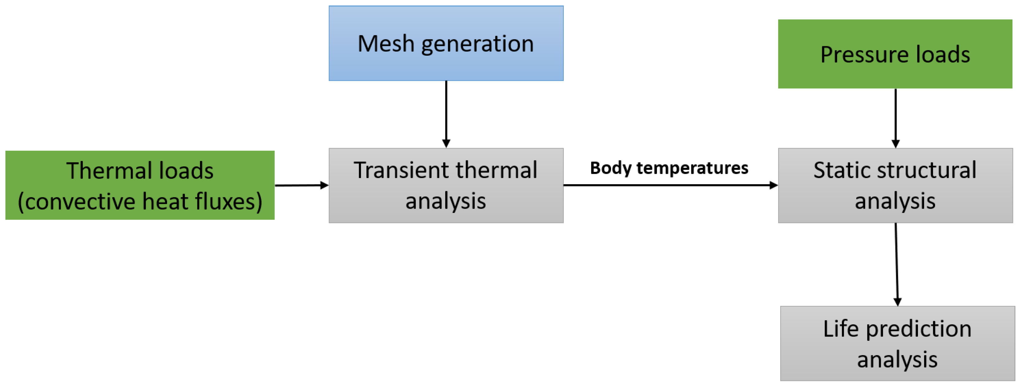
4. Thermal–Structural Cycle Description
- a purging phase of 3 s, in which the liquid oxygen is injected into the channels to eliminate any waste;
- an ignition transient phase of 3 s, in which the thermal loads are activated;
- the hot phase of 100 s, during which the creep analysis is activated.
5. Life Prediction Models
5.1. Ratcheting
5.2. Creep
5.3. Multiaxial LCF—Non Proportional Loading
6. Results and Discussions
7. Conclusions
Author Contributions
Funding
Institutional Review Board Statement
Informed Consent Statement
Data Availability Statement
Acknowledgments
Conflicts of Interest
References
- Chaboche, J.L. Time-independent constitutive theories for cyclic plasticity. Int. J. Plast. 1986, 2, 149–188. [Google Scholar] [CrossRef]
- Chaboche, J.L. A review of some plasticity and viscoplasticity constitutive theories. Int. J. Plast. 2008, 24, 1642–1693. [Google Scholar] [CrossRef]
- Asraff, A.K.; Sheela, S.; Paul, A.; Mathew, A.; Savithri, S. Cyclic stress analysis of a rocket engine thrust chamber using chaboche, voce and creep constitutive models. Trans. Indian Inst. Met. 2016, 69, 495–500. [Google Scholar] [CrossRef]
- Palma, M.D. Hardening parameters for modelling of CuCrZr and OFHC copper under cyclic loadings. In Proceedings of the 2013 IEEE 25th Symposium on Fusion Engineering (SOFE), San Francisco, CA, USA, 10–14 June 2013; pp. 1–5. [Google Scholar] [CrossRef]
- Song, J.; Sun, B. Thermal-structural analysis of regeneratively-cooled thrust chamber wall in reusable LOX/Methane rocket engines. Chin. J. Aeronaut. 2017, 30, 1043–1053. [Google Scholar] [CrossRef]
- Riccius, J.R.; Haidn, O.J.; Zametaev, E.B. Influence of time dependent effects on the estimated life time of liquid rocket combustion chamber walls. In Proceedings of the 40th AIAA/ASME/SAE/ASEE Joint Propulsion Conference and Exhibit, Fort Lauderdale, FL, USA, 11–14 July 2004. [Google Scholar]
- Thiede, R.G.; Riccius, J.R.; Reese, S. Life prediction of rocket combustion-chamber-type thermomechanical fatigue panels. J. Propuls. Power 2017, 33, 1529–1542. [Google Scholar] [CrossRef]
- Riccius, J.; Hilsenbeck, M.; Haidn, O. Optimization of geometric parameters of cryogenic liquid rocket combustion chambers. In Proceedings of the 37th Joint Propulsion Conference and Exhibit, Salt Lake City, UT, USA, 8–11 July 2001. [Google Scholar]
- You, J.-H.; Miskiewicz, M. Material parameters of copper and CuCrZr alloy for cyclic plasticity at elevated temperatures. J. Nucl. Mater. 2008, 373, 269–274. [Google Scholar] [CrossRef] [Green Version]
- Li, G.; Thomas, B.G.; Stubbins, J.F. Modeling creep and fatigue of copper alloys. Metall. Mater. Trans. A 2000, 31, 2491–2502. [Google Scholar] [CrossRef]
- Ferraiuolo, M.; Russo, V.; Vafai, K. A comparative study of refined and simplified thermo-viscoplastic modeling of a thrust chamber with regenerative cooling. Int. Commun. Heat Mass Transf. 2016, 78, 155–162. [Google Scholar] [CrossRef]
- Ferraiuolo, M.; Petrillo, W.; Riccio, W. On the thermo-structural response of a composite closeout in a regeneratively cooled thrust chamber. Aerosp. Sci. Technol. 2017, 71, 402–411. [Google Scholar] [CrossRef]
- Golan, O.; Arbel, A.; Eliezer, D.; Moreno, D. The applicability of Norton’s creep power law and its modified version to a single-crystal superalloy type CMSX-2. Mater. Sci. Eng. A 1996, 216, 125–130. [Google Scholar] [CrossRef]
- Wang, C.H.; Brown, M.W. A path-independent parameter for fatigue under proportional and non-proportional loading. Fatigue Fract. Eng. Mater. Struct. 1993, 16, 1285–1297. [Google Scholar] [CrossRef]
- Ferraiuolo, M.; Leo, M.; Citarella, R. On the adoption of global/local approaches for the thermomechanical analysis and design of liquid rocket engines. Appl. Sci. 2020, 10, 7664. [Google Scholar] [CrossRef]
- Porowski, J.S.; O’Donnell, W.; Badlani, M.L.; Kasraie, B.; Kasper, H.J. Simplified design and life prediction of rocket thrust chambers. J. Spacecr. Rocket. 1985, 22, 181–187. [Google Scholar] [CrossRef]
- Calì, C.; Cricrì, G.; Perrella, M. An advanced creep model allowing for hardening and damage effects. Strain 2010, 46, 347–357. [Google Scholar] [CrossRef]
- Giannella, V.; Citarella, R.; Fellinger, J.; Esposito, R. LCF assessment on heat shield components of nuclear fusion experiment “Wendelstein 7-X” by critical plane criteria. Procedia Struct. Integr. 2018, 8, 318–331. [Google Scholar] [CrossRef]
- Giannella, V.; Citarella, R.; Fellinger, J.; Esposito, R. Multiaxial LCF assessment on plasma facing components of nuclear fusion experiment wendelstein 7-X. In Proceedings of the 23rd Conference of the Italian Association of Theoretical and Applied Mechanics (AIMETA 2017), Salerno, Italy, 4–7 September 2017; Volume 1, pp. 1047–1061. [Google Scholar]
- Citarella, R.; Giannella, V.; Vivo, E.; Mazzeo, M. FEM-DBEM approach for crack propagation in a low pressure aeroengine turbine vane segment. Theor. Appl. Fract. Mech. 2016, 86, 143–152. [Google Scholar] [CrossRef]
- Giannella, V.; Vivo, E.; Mazzeo, M.; Citarella, R. FEM-DBEM approach to simulate crack propagation in a turbine vane segment undergoing a fatigue load spectrum. Procedia Struct. Integr. 2018, 12, 479–491. [Google Scholar] [CrossRef]
- Fellinger, J.; Citarella, R.; Giannella, V.; Herold, F.; Stadler, R. Overview of fatigue life assessment of baffles in Wendelstein 7-X. Fusion Eng. Des. 2018, 136, 292–297. [Google Scholar] [CrossRef] [Green Version]
- Sepe, R.; Giannella, V.; Greco, A.; De Luca, A. Fem simulation and experimental tests on the smaw welding of a dissimilar t-joint. Metals 2021, 11, 1016. [Google Scholar] [CrossRef]
- Liu, D.; Sun, B.; Wang, T.; Song, J.; Zhang, J. Thermo-structural analysis of regenerative cooling thrust chamber cylinder segment based on experimental data. Chin. J. Aeronaut. 2019, 33, 102–115. [Google Scholar] [CrossRef]
- Ferraiuolo, M.; Ricci, D.; Battista, F.; Roncioni, P.; Salvatore, V. Thermo-structural and thermo-fluid dynamics analyses supporting the design of the cooling system of a methane liquid rocket engine. In Proceedings of the ASME 2014 International Mechanical Engineering Congress and Exposition, Montreal, QC, Canada, 14–20 November 2014; Volume 1. [Google Scholar] [CrossRef]
- Bari, S.; Hassan, T. Anatomy of coupled constitutive models for ratcheting simulation. Int. J. Plast. 2000, 16, 381–409. [Google Scholar] [CrossRef]
- Marzec, J.; Marzec, L.; Martus, P.; Zips, D.; Müller, A.-C. MATLAB®-based fitting method to evaluate survival fractions after multimodal treatment. Clin. Transl. Radiat. Oncol. 2018, 10, 36–41. [Google Scholar] [CrossRef] [Green Version]
- Steel, R.G.D.; Torrie, J.H. Principles and Procedures of Statistics; With Special Reference to the Biological Sciences; McGraw-Hill Book Company: New York, NY, USA; Toronto, ON, Canada; London, UK, 1960. [Google Scholar] [CrossRef]
- Ricci, D.; Battista, F.; Fragiacomo, M. Numerical investigation on the thermal behaviour of a LOx/LCH4 demonstrator cooling system. Aerospace 2021, 8, 151. [Google Scholar] [CrossRef]
- Itoh, T.; Sakane, M.; Ohsuga, K. Multiaxial low cycle fatigue life under non-proportional loading. Int. J. Press. Vessel. Pip. 2013, 110, 50–56. [Google Scholar] [CrossRef]
- Gowhari-Anaraki, A.R.; Hardy, S.J. Low cycle fatigue life predictions for hollow tubes with axially loaded axisymmetric internal projections. J. Strain Anal. Eng. Des. 1991, 26, 133–146. [Google Scholar] [CrossRef]


| D1 | D2 | D3 | D4 | D5 | D6 | D7 |
|---|---|---|---|---|---|---|
| 3 | −0.92 | 23,695 | 14 | 23,695 |
| Temperature | Thermal Conductivity | Thermal Expansion Coefficient | ||
|---|---|---|---|---|
| 300 | 8933 | 320 | 390 | |
| 600 | 8933 | 290 | 390 | |
| 900 | 8933 | 255 | 400 |
| Temperature [K] | Young’s Modulus E | Poisson’s Ratio ν [-] | Yield Stress [MPa] | Ultimate Tensile Strength [MPa] |
|---|---|---|---|---|
| 300 | 130 | 0.3 | 433.9 | 477.9 |
| 500 | 106 | 0.3 | 383.3 | 402.9 |
| 700 | 87 | 0.3 | 313 | 329.4 |
| 900 | 44 | 0.3 | 156.3 | 174.5 |
| Temperature | Thermal Conductivity | Thermal Expansion Coefficient | ||
|---|---|---|---|---|
| 300 | 8913 | 390 | 385 |
| Temperature [K] | Young’s Modulus E | Poisson’s Ratio ν [-] | Yield Stress [MPa] | Ultimate Tensile Strength [MPa] |
|---|---|---|---|---|
| 28 | 118 | 0.34 | 68 | 413 |
| 294 | 114 | 0.34 | 60 | 208 |
| 533 | 65 | 0.34 | 50 | 145 |
| 755 | 40 | 0.34 | 38 | 80 |
| Temperature | Thermal Conductivity | Thermal Expansion Coefficient | ||
|---|---|---|---|---|
| 300 | 8913 | 90 | 444 |
| Temperature [K] | Young’s Modulus E | Poisson’s Ratio ν [-] | Yield Stress [MPa] | Ultimate Tensile Strength [MPa] |
|---|---|---|---|---|
| 28 | 193 | 0.3 | 344 | 551 |
| Number of Elements in the Ligament Thickness [-] | Equivalent Creep Strain [-] | Equivalent Plastic Strain [-] | Temperature [K] |
|---|---|---|---|
| 4 | 0.004896 | 0.001415 | 556 |
| 6 | 0.00497 | 0.001541 | 556 |
| 8 | 0.00499 | 0.001599 | 556 |
| Load Steps [-] | ∆t [s] | Duration [s] | Phase |
|---|---|---|---|
| 10 | 0.1 | 1 | Purging |
| 5 | 0.4 | 2 | Purging |
| 15 | 0.2 | 3 | Ignition Transient |
| 1 | 100 | 100 | Hot Phase |
Publisher’s Note: MDPI stays neutral with regard to jurisdictional claims in published maps and institutional affiliations. |
© 2022 by the authors. Licensee MDPI, Basel, Switzerland. This article is an open access article distributed under the terms and conditions of the Creative Commons Attribution (CC BY) license (https://creativecommons.org/licenses/by/4.0/).
Share and Cite
Ferraiuolo, M.; Perrella, M.; Giannella, V.; Citarella, R. Thermal–Mechanical FEM Analyses of a Liquid Rocket Engines Thrust Chamber. Appl. Sci. 2022, 12, 3443. https://doi.org/10.3390/app12073443
Ferraiuolo M, Perrella M, Giannella V, Citarella R. Thermal–Mechanical FEM Analyses of a Liquid Rocket Engines Thrust Chamber. Applied Sciences. 2022; 12(7):3443. https://doi.org/10.3390/app12073443
Chicago/Turabian StyleFerraiuolo, Michele, Michele Perrella, Venanzio Giannella, and Roberto Citarella. 2022. "Thermal–Mechanical FEM Analyses of a Liquid Rocket Engines Thrust Chamber" Applied Sciences 12, no. 7: 3443. https://doi.org/10.3390/app12073443
APA StyleFerraiuolo, M., Perrella, M., Giannella, V., & Citarella, R. (2022). Thermal–Mechanical FEM Analyses of a Liquid Rocket Engines Thrust Chamber. Applied Sciences, 12(7), 3443. https://doi.org/10.3390/app12073443