Featured Application
This research presents the transient torsional vibration due to cutting action of a propeller rope cutter. Therefore, a method to determine the safety diameter of connecting bolts was described regarding the fatigue strength of the propulsion system. The installation of the rope cutter does not significantly reduce the ship’s power performance or increase the structural vibration.
Abstract
Nowadays, damage to ships due to marine debris at sea is increasingly reported. Specifically, a piece of rope or fishing net can wrap around the propeller shaft, stopping it from rotating. Although various efforts have been made, there are still numerous practical challenges. A rope cutter system, which was designed to cut suspended objects wrapped around the propeller shaft, offers a great advantage in protecting the propulsion system. Since the cutting action produces the transient torsional vibration, the connecting bolts should be stable and sufficiently rigid under normal conditions. However, in the event of an encounter with an object that is too hard to cut, the bolts must be broken so that the rope cutter is released. Those kinds of objects may not be long enough to wrap around the shaft, such as a piece of wood. Therefore, this research presents the novelty in maintaining the safety of the propulsion system installed with a rope cutter. In this study, a method for obtaining the maximum diameter of the connecting bolt as a safety device is described, and the torques required to cut ropes of various thicknesses were determined based on actual measurements. Finally, a series of experiments in the laboratory-scale and shipboard test on an actual ship show that the rope cutter does not significantly reduce the ship’s power performance or increase the structural vibration.
1. Introduction
Korea is a country with many islands as well as very busy fishing ships. Accompanied by that bustle, there is an increase in the amount of waste in the sea posing a danger to ships [1,2,3,4]. At least in the seas of Korea, the annual inflow of marine debris was estimated to be 91,195 tons. Of this, the land-based sources account for 36% (32,825 tons), whereas the sea-based sources account for 64% (58,370 tons) [5]. A rope or a piece of fishing net can wrap around the propeller shaft and then prevent the propeller from rotating. Accidents due to these suspended objects are frequently reported at least once a week. The accident rate is expected to increase further in the future due to the increased operating time and intensification of ships in the fishing area, as well as competitive fishing activities. Most accidents delay the sailing schedule by at least one hour or more, resulting in increased financial costs [6,7,8]. Sending a diver underwater to solve this problem is potentially risky, not just in rough weather. A vessel not under command (NUC) at sea may become an obstacle and then endanger other ships moving nearby. In a more serious case, a rope can immediately stop the rotating propeller, damage the transmission gears, shut the engine off, or even drop the engine off the platform. If a rope remains entangled in the propeller shaft and continues to rotate around the seal, it will eventually cut the seal and cause the propeller shaft seals to leak. Hall also mentioned incidents where fishing line wrapped into the stern seal [9]. During strong waves and winds at sea, many cases of ship overturning accidents have been reported. The ship named Dolgorae capsized, causing the death of 15 people and 3 missing people [10,11,12]. The MV Seohae ferry sank on 10 October 1993 in the Yellow Sea due to a 10 mm thick nylon rope wrapped around the two propeller shafts, killing 292 of the 362 passengers and crew on board [13,14,15].
To avoid that kind of accident in advance, many efforts have been made to remove the harmful substances by increasing the activities of collecting the floating materials at sea such as abandoned fishing nets and ropes [16]. This work is helpful but it is very laborious and not efficient enough since it is impossible to remove all the harmful substances at sea. In addition, although the propulsion systems without propellers, such as water jet propulsion [17,18], have been developed and applied, there are practical limitations such as high capital expenditure for installation on a small ship. Another solution is to install a rope guard, which acts as a barrier to protect the propeller shaft from line entanglement [19,20]. However, there is a problem that the downside of this device increases the weight and water drag, forcing the engine to generate more power for the same ship speed. Besides, after a while, it will be fouled and contaminated at times, making it difficult for inspections or repairs.
In this study, the development of a rope cutter is concerned. This cutting system is an assembly of two main parts. The static part includes a non-rotary blade held by a holding block, which is fixed on the propeller shaft strut housing by bolts. The rotating part including two blades is mounted on the propeller shaft and rotates together. It was designed to cut anything that is wrapped around the propeller shaft, such as a rope or a piece of fishing net. The rope cutter had posed a great advantage in protecting the propeller shaft from suspended objects. However, the cutting action produces the transient torsional vibration, similar to an ice-propeller interaction [21,22,23,24,25]. After many of these actions, the lifetime of the propulsion system is shortened due to cumulative fatigue. Furthermore, if the tangled object is too hard for the cutting capability, it can stop the shaft immediately or significantly damage the shaft in terms of fatigue strength. That object may not be long enough to wrap around the shaft, such as a piece of wood. In that case, the cutter should be released to protect the propulsion system.
Currently, there is very limited research available on rope cutters. The structural stability and effectiveness of a rope cutter has been evaluated by Kim et al. [26]. Further research on similar disc cutters such as the sugarcane cutter can be referred to as well. Yang et al. used finite element method (FEM) and the smoothed particle hydrodynamics (SPH) coupled method to simulate the forces acting on the cutter blade surfaces [27]. Kroes and Harris investigated the relationship between the disc rotating speed with the cutting quality [28]. The cutting energy has been studied by Kroes and Hogarth [29]. Liu et al. established the theoretical cutting force formula by elastic theory analysis [30]. However, there have not yet been any studies on the effects of cutting action on the rotating shaft. This research presents the novelty of keeping the safety for the propulsion system with a rope cutter. It shows a different perspective on the rope cutter: how it can damage the shafts during cutting actions. Therefore, the method of calculating the maximum diameter of the connecting bolt is described. The bolts should not only be strong enough to hold the cutter working stably under normal conditions, but also can be destroyed easily if encountered by a too hard object. In addition to the above, it is also important to verify the transient torques required to cut ropes of varying thickness by actual measurements. When the generated torque is too high, the stress produced on the shaft is greater than the permissible value, so the connecting bolt should be destroyed to release the cutter. Based on this, the cutting capacity of the cutter can be obtained. To increase the cutting capability, the cutting performance must be improved by modifying the cutter or changing to the other type. A series of experiments in the lab-scale and shipboard test on an actual ship were carried out to investigate the transient torsional vibration caused by cutting action. Moreover, the effects of the rope cutter to the power performance and the vibration of propulsion system were evaluated.
2. Permissible Torsional Stresses Determination
2.1. Permissible Torsional Stresses Amplitude for Transient Vibration
For continuous operation, it is determined in IACS UR M68 [31] that the permissible stresses due to alternating torsional vibration shall not exceed the values by the following formulae:
or
where:
- τC = permissible stress amplitude (N/mm2) due to torsional vibration for continuous operation,
- σB = specified minimum tensile strength of shaft material = 600 (N/mm2),
- d = actual shaft outside diameter = 120 mm,
- cK = design factor for intermediate shaft with shrink fit coupling = 1,
- cD = size factor, = 0.35 + 0.93 · do−0.2 = 0.707,
- λ = speed ratio = n/n0,
- n = shaft speed under consideration (rpm), and
- n0 = shaft speed at rated power (rpm).
The permissible stress is usually calculated for the intermediate shaft, which is smaller than the propeller shaft. This design ensures that, in the event of a failure, the intermediate shaft will be broken in advance to protect the propeller shaft that is more difficult to repair or replace. The same specifications as for the propulsion system in the shipboard test in Section 4 were used for this calculation. The lowest permissible stress is calculated at maximum rotating speed:
The transient permissible stress given by the following formula represents the level that should not be exceeded in any case:
Finally, the permissible alternative torque in the intermediate shaft for the transient fluctuation during cutting action can be obtained as below:
or 23.8 kN·m.
2.2. Permissible Torsional Stresses Concerning Fatigue Strength
2.2.1. The Low Cycle Criteria
The permissible low cycle torsional vibratory stress can be calculated by [12]:
with:
- τ = mean torsional stress at variety of shaft speed (N/mm2),
- σy = specified minimum yield strength of shaft material = 0.7 × σB = 420 (N/mm2),
- SL = safety factor, SL = 1.25, recommended by DNV AS for low cycle criteria [32], and
- KL = component influence factor for low cycle fatigue, KL = 1.06, calculated according to DNV AS [33].
Finally, the permissible low cycle torsional vibratory stress can be obtained:
In the case of operating at maximum speed, n0 = 517 rpm, and the nominal power, P0 = 633,000 W, the nominal torque of the intermedia shaft is:
Then, the nominal stress is:
Therefore, the permissible low cycle torsional vibratory stress for maximum speed is, N/mm2.
2.2.2. The High Cycle Criteria
The permissible high cycle torsional stress can be calculated by [33]:
where:
- SH = safety factor, SH = 1.6, recommended by DNV AS for low cycle criteria [32], and
- = component influence factor for high cycle torsional fatigue, = 1.26, calculated according to DNV AS [33].
At maximum speed, the nominal stress is: N/mm2. Finally, the permissible high cycle torsional stress can be obtained: N/mm2.
2.2.3. The Torsional Stress Criterion
The most important aspect of the calculation is the estimation of the low-cycle and high-cycle criteria corresponding to each specific torque. For transient torsional vibration, DNV AS recommends choosing the number of reversals for low-cycle and high-cycle fatigue as and , respectively [32]. One cycle includes two stress reversals. In this case, (N) denotes the number of cycles and (2N) denotes the number of reversals. As described in Figure 1, the fractional damage can be determined at each torsional stress level, i.e., one reversal at stress level makes a fractional damage of , and one reversal at stress level makes a fractional damage of . That is the linear relationship in log-log scale according to the Miner’s rule for cyclic/time-variant loading [34]. The failure occurs when the accumulated fractional damage reaches the value of 1 [35,36].
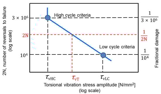
Figure 1.
Relationship between the torsional vibration stress amplitude, the number of reversals to failure, and the fractional damage.
The torsional stress amplitude corresponding to failure at (2N) reversals is calculated by:
In case that the cutting action occurs once every week, resulting in 520 times for 10 years, corresponding to 2N = 520 reversals, then the corresponding transient critical torsional vibration stress is = 64.5 N/mm2. The critical alternative torque in the intermediate shaft for the transient fluctuation during cutting action is:
or 21.9 kN·m.
Assuming the cutting action occurs once every day, then the corresponding transient torsional stress is = 52.7 N/mm2. The permissible alternative torque is kN·m.
3. Permissible Torsional Stresses Determination
3.1. Methodology
In this section, we will find out the critical bolt diameter for a rope cutter installed on the same propulsion system as Section 2, with the following specifications:
- -
- Intermedia shaft diameter, d = 120 mm,
- -
- Tensile strength of intermediate shaft, MPa,
- -
- Tensile strength of connecting bolt, MPa. More details of intermediate shaft and connecting bolt materials are described in Table 1.
 Table 1. Specifications of the intermediate shaft and connecting bolt materials.
 - -
- Shear strength of bolt, MPa,
- -
- Distance from center of bolt to center of moment, mm, see Figure 2,
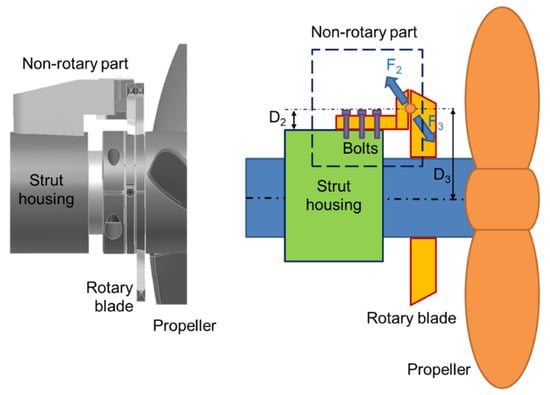 Figure 2. Illustration of rope cutter system and cutting forces.
 - -
- Vertical distance from rope cutting point to shear section of bolt, mm,
- -
- Distance from rope cutting point to center of propeller shaft, mm.
During operation, the connecting bolts are subjected to tensile and shear force, as shown in Figure 3. The body part has the cross section equal to 1.161 times the area of the threaded part. Shear failure occurs only in the cutting section. The cutting forces, F2 = F3, are generated when trying to cut a rope. Force, F3, creates a torque on the shaft:
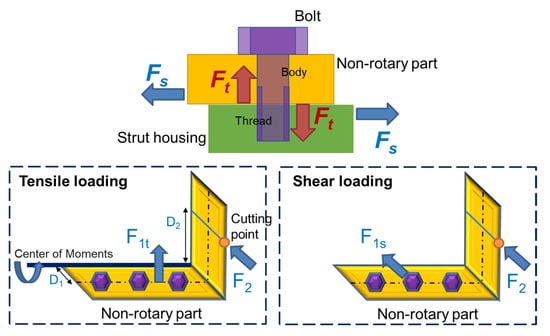
Figure 3.
Tensile and shear forces applied to bolts.
The additional torsional stress applied on the intermediate shaft is calculated by:
The opposite force, , creates tension and shear forces on bolts. The forces producing tension are denoted by and ; the others producing shear are denoted by and . Applying the equivalent condition, we get:
and
Assuming that the forces distribute equally on all bolts, the forces applied on each bolt in tension and shear are determined by:
and
The tensile and shear stresses created on each bolt are:
and
In this case of combined shear and uniaxial tension loading, to predict the ultimate failure, the maximum tensile and shear stresses are given as follows [37]:
and
The destruction is defined when the maximum shear stress is or the maximum tensile stress is ; the above equations can then be written as the following failure criteria:
and
Then the criteria cross section area of the connecting bolt is obtained by the larger of followings:
or
The criteria diameter is determined corresponding to specified failure conditions as shown in Figure 4.
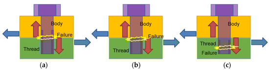
Figure 4.
Specified failure conditions of the connecting bolt due to the combination of tension and shear. (a) The shear section and the failure are at the threaded part of the bolt; (b) The shear section and the failure are at the body part of the bolt; (c) The shear section is at the body part, where the failure is at the threaded part of the bolt.
3.1.1. Case 1. The Shear Section Is at the Threaded Part of Bolt
In this case, the shear section is at the thread part of bolt. It is under the combined tension and shear load. The body part has a large section area, but it is under tension load only. The failure (if available) occurs as described in Figure 4a. That is predicted when the bolt diameter is less than any value of the following:
or
In other words, the critical diameter of the bolt is determined by the largest result in Equations (28) and (29).
3.1.2. Case 2. The Shear Section Is at the Body Part of Bolt
In this case of assembly, the body part has a larger section area but is under both tension and shear loading. The threaded part is under tension only. The ultimate failure may occur at the shear section, as described in Figure 4b. The critical diameter of the bolt is determined by the larger of the following:
or
The failure may also occur at the threaded part, which has smaller section, as seen in Figure 4c. The critical diameter of the bolt is determined by:
In summary, the critical diameter of the bolt in this case of assembly is the largest result in Equations (30)–(32).
3.2. Results and Discussion
As discussed in Section 2, the permissible alternating torque of the intermediate shaft for the transient torsional vibration is 23.8 kN·m. The permissible alternating torque for 520 reversals concerning fatigue lifetime is 21.9 kN·m. The lower value is used to calculate for the safety of the propulsion system. Therefore, the cutting forces at the blades are determined:
The distributions of force, , for the tension and shear loads are unknown. It depends on how the cutter system is installed. In this calculation, all the cases of force distribution are concerned. In each specified assembly condition, the criteria diameter of the bolt is determined by the following.
3.2.1. Case 1. The Shear Section Is at the Threaded Part of Bolt
The critical bolt diameter values by varying the distribution for tension are shown in Figure 5. In case of 90% tension distribution (10% shear, total 100%), the critical diameter of the bolt is 9.2 mm. When the force distribution is unknown, the bolt diameter should be less than the smallest value of the bolt safety zone. In this calculation, it is 7.6 mm when the tension distribution is 30%. If the diameter is in the bolt safety zone, the bolt is more difficult to be broken to release the cutter. That can seriously damage the shaft concerning fatigue strength due to rope cutting action.
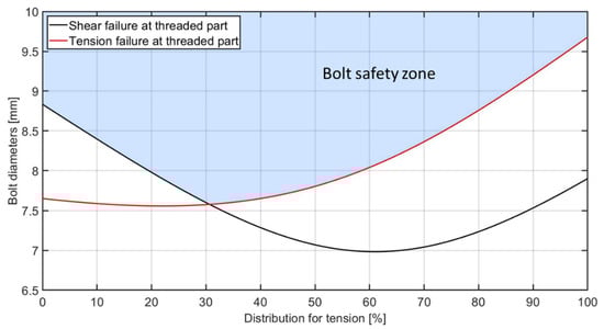
Figure 5.
Critical bolt diameter values by varying the distribution for tension (Case 1).
3.2.2. Case 2. The Shear Section Is at the Body Part of Bolt
The failure position depends on the distributions of shear and tension as shown in Figure 6. Accordingly, when the distribution of tension is over 58%, the weakest point is at the threaded part of the bolt. Therefore, this part is the easiest to break. In the opposite case, the failure is more likely to occur at the body part. For an example, in the assumption of 90% tension force distribution, the calculation concerns the failure at the threaded part. As a result, the critical diameter of the bolt is determined by 9.2 mm. When the force distribution is unknown, the bolt diameter should be less than 7 mm in case of 30% of tension distribution. Therefore, to protect the shaft, the bolt diameter should be less than the critical value to ensure that the bolts will be destroyed when encountering an object that is too large. That object is most likely not long enough to wrap around and stop the propeller.
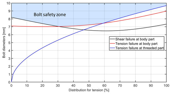
Figure 6.
Criteria bolt diameter values by varying the distribution for tension (Case 2).
4. Experiments in a Water Tank in the Laboratory-Scale
A water tank has been set up in the laboratory of the Korea Maritime and Ocean University. In the test rig, an electric motor-driven propeller propulsion system was installed, as shown in Figure 7 and Table 2. A strain gauge with a telemetry system was applied to measure the stress at the intermediate shaft as well as the shaft power. The telemetry system of MANNER Sensortelemetrie GmbH consists of a type FSV_8c sensor signal amplifier that rotates with the shaft and a type of AW_22TE evaluation unit (signal receiver). The zero-point drift (accuracy) is less than 0.02%/°C. The sensitivity is 0.05 to 20 mV/V with a bandwidth of 0 to 1 kHz. The rope cutter operation was evaluated via the power performance test and the transient torsional vibration measurement during cutting action.
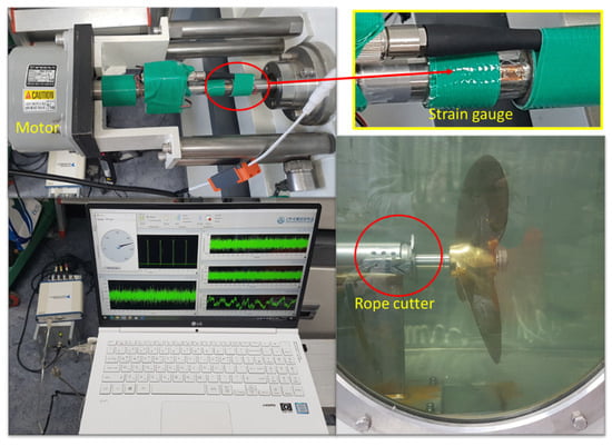
Figure 7.
Experimental setup for the test in the laboratory-scale.
Table 2.
Specifications of the propulsion system in the laboratory-scale experiment.
4.1. Power Performance Test
The purpose is to compare the power performance of the propulsion system between cases with and without a rope cutter. The engine speed slowly increased from 20 to 230 rpm. As a result, the power performance is almost the same for both conditions, as described in Figure 8. In case of the installed rope cutter, the fluctuation in shaft power is a bit greater at 212 rpm. This occurs due to the turbulence in the water flow, but not significantly. It may not happen in an open water condition. Thus, it can be concluded that the installation of the rope cutter does not affect the efficiency of the propulsion system.
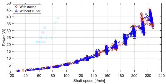
Figure 8.
Power performance comparison in water tank test.
4.2. Transient Torque during the Cutting Action
Ropes of different diameters were inserted into the cutter. They are made from polypropylene, as shown in Figure 9, which is commonly used in fishing activities. The strain gauge measured transient torsional vibration at the intermediate shaft due to the cutting action. It was very difficult to put the rope into the cutter in the same way every time. Figure 10 and Figure 11 show the measured stresses in a test of ∅12 rope at 100 and 200 rpm, respectively. They were the same ropes, but the results of each test are different. To clarify this issue, it is necessary to find out what happened after a rope was put into the cutter. The rope was braided with lots of small polypropylene fibers. At first, the blades of cutter squeezed the rope and deformed it into a flatter shape. The shapes were not perfectly the same between cuts. The cutting could start later, resulting in shorter cutting time, and vice versa. As a result, in the case that the cutting time is shorter, the peak of the cutting force increases, but the work done to cut remains the same. As seen in Figure 10, the cutting duration of cut No.1 is longer than the others, resulting a smaller peak.
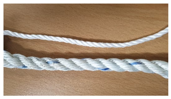
Figure 9.
Polypropylene ropes for the cutting test in the laboratory-scale.
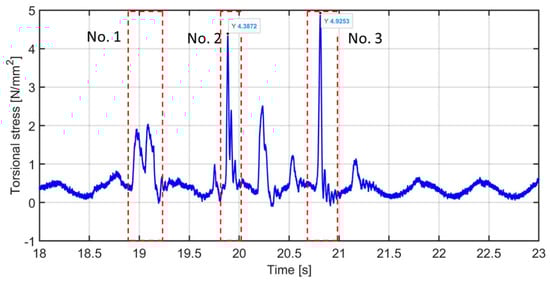
Figure 10.
Measured stress of the cutting test with ∅12 rope at 100 rpm.
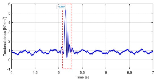
Figure 11.
Measured stress of the cutting test with ∅12 rope at 200 rpm.
Cutting at a higher or lower position also changes the distance from the cutting point to the shaft center line, resulting in a change in torque. In addition, the cutting force highly depends on how to insert the rope into the cutter, concerning the shape of the cutting section. When the rope is perpendicular to the cutting blade, the shape of the cutting section is a circle with the smallest area as well as the smallest cutting force. In this experiment, the cutting point was set at 33 mm from shaft center line. After iterative testing, the result shows that the shaft speed does not affect the cutting force much. Taking the average values, the measurement results are obtained in Table 3.
Table 3.
Shear stress amplitude in rope due to cutting action.
For the same material, the shear stresses in rope due to cutting actions are almost the same regardless of the rope diameter. Therefore, the transient torsional stress can be estimated in advance to protect the shaft from fatigue failure. For example, a stress of 12.5 N/mm2 is estimated when cutting a ∅20 polypropylene rope by this cutter system. If the stress amplitude is too large, the cutter needs to be modified or changed to improve the cutting performance. Using the same method as described in Section 2, the permissible shear stress for transient torsional vibration of the intermediate shaft is calculated as 107.7 N/mm2. Therefore, the maximum diameter of rope that can be safely cut is 59.4 mm. The cutting capacity of this cutter is determined.
5. Experiment in the Shipboard Test on an Actual Ship
A rope cutter system has been installed on a passenger ferry. The main technical data of ship and propulsion plant are summarized in Table 4. The experiment procedure is as follows:
Table 4.
Specifications of the ship and propulsion system in the shipboard test.
- -
- The engine stops, the ship stops.
- -
- A diver hooks a rope into the cutter system.
- -
- Start the engine, run at a speed of 600 rpm (ready to engage).
- -
- Engage the clutch to rotate the propeller shaft, and then the rope is cut immediately.
Test No. 1 was carried out with a ∅50 rope for cutting and test No. 2 used a fishing net, as shown in Figure 12. Both are made of polypropylene. The measured vibration results are compared to the normal engagement. As with the laboratory tests, a strain gauge was installed at the intermediate shaft to measure the transient torsional vibration due to the cutting actions. The roller encoder measured the rotating angular velocity. The accelerometers were mounted on the engine body for the structure vibration measurement. The measurement diagram is described in Figure 13.
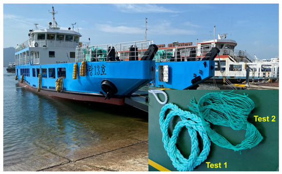
Figure 12.
The overview of passenger ferry and cutting test materials (rope, net).
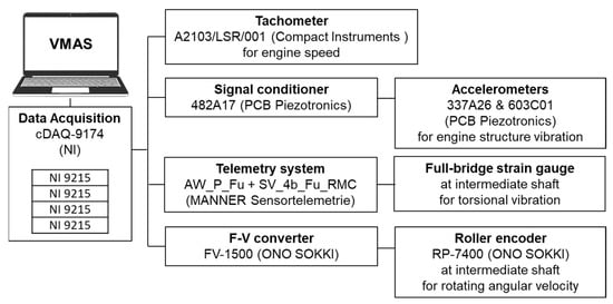
Figure 13.
Schematic diagram of the vibration measurement system in the shipboard test.
When the gear clutch engaged with the cut, the torsional vibration stresses were greater in the comparison with the normal engagement as described in Figure 14 and Figure 15. Those oscillations were due to the cutting actions. In case of test No. 1, after the first one, the cutting occurred 2 more times because the rope continued to move into the cutter with the flow of water. As calculated in Section 2, the permissible transient torsional stress is determined by the lower value as 64.5 N/mm2 for 520 reversals. The transient torsional vibration amplitudes due to cutting action were less than 5 N/mm2, which is significantly smaller than the clutch engaging torsional fluctuation, 34 N/mm2, which occurs many times daily. The maximum diameter of rope that can be safely cut is calculated as 180 mm. The cutting capacity of this cutter is determined. After clutch engaging, the angular velocity of the propeller shaft increased quickly, as shown in Figure 16 and Figure 17. The cutting action affected the angular velocity slightly; it was lower but not remarkable in both test cases. The difference in engine structure vibration was very insignificant. There was almost no effect of rope cutting to the engine body.
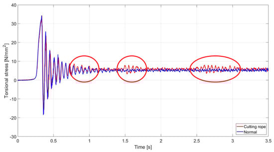
Figure 14.
Comparison of torsional vibration stress at the intermediate shaft during engaging test No. 1.
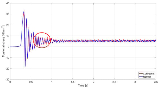
Figure 15.
Comparison of torsional vibration stress at the intermediate shaft during engaging test No. 2.
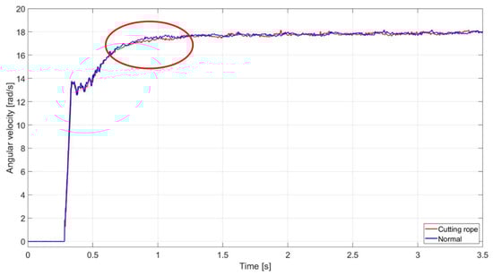
Figure 16.
Comparison of rotating angular velocity at the intermediate shaft during engaging test No. 1.
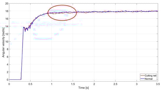
Figure 17.
Comparison of rotating angular velocity at the intermediate shaft during engaging test No. 2.
The performance test also was employed with the vibration measurements. The engine speed increased slowly from minimum to maximum. The rope cutter did not change the vibration characteristic of the propulsion system. The ship could reach the same speed as before, 13.5 knots, at 1800 rpm.
6. Conclusions
The rope cutter system poses a great advantage in protecting the propulsion system. However, it produces transient torsional vibration during the cutting action. In this study, the optimal size selection and calculation method of the connecting bolt for the rope cutter was studied considering the permissible torsional stress of the propulsion shaft. If the rope cutter encounters foreign substances that cannot be cut, such as a large diameter rope or a piece of wood, the connecting bolts can be damaged first either in the thread or body part according to the force distribution condition so that the rope cutter is released, thereby ensuring the safety of the ship’s engine and propulsion system. Therefore, by applying this method when designing scaled rope cutters in actual application, it is considered that the connecting bolts can act as a safety device to protect the propulsion system. Moreover, the effect of the rope cutter on the power performance and transient torsional stress characteristics of the propulsion system was studied on the basis of experiments in a water tank and in the shipboard test. In both tests, a strain gauge with a telemetry system was used to measure the transient torsional stress at the intermediate shaft. From the result of the experiment in a water tank, it was found that the shear stress of ropes with the same material was almost the same regardless of the rope diameter, and the transient torsional stress can be estimated to prevent fatigue failure of the shaft. Then, regarding the permissible transient torsional stress, the cutting capability of the cutter system was determined as the rope diameter of 59.4 mm for the laboratory-scale experimental system and 180 mm for the propulsion system in the shipboard test. These results are applied for the polypropylene objects, which are the most common marine debris. In case of the other material, the same experiment can be performed to determine the corresponding cutting capacity of the cutter system. Finally, it was confirmed that the operation of the rope cutter has no significant effect on the power performance and the structure vibration characteristic of the propulsion system.
Author Contributions
W.-S.K. and Q.D.V. have contributed equally to this work. Conceptualization, W.-S.K., Q.D.V. and W.-J.L.; methodology, W.-S.K., Q.D.V. and W.-J.L.; software, S.-K.Y.; validation, Q.D.V., W.-J.L.; formal analysis, Q.D.V.; investigation, S.H.Y. and M.-H.P.; resources, W.-J.L.; data curation, A.J.N.; writing—original draft preparation, Q.D.V. and W.-S.K.; writing—review and editing, J.-u.L., J.-w.L. and W.-J.L.; visualization, W.-S.K.; supervision, J.-H.C.; project administration, J.-H.C. and W.-J.L.; funding acquisition, W.-J.L. All authors have read and agreed to the published version of the manuscript.
Funding
This research was supported by the BK21 Four program through the National Research Foundation of Korea (NRF) funded by the Ministry of Education of Korea(Center for Creative Leaders in Maritime Convergence) and by the “Leaders in Industry-university Cooperation +” Project funded by the Ministry of Education and National Research Foundation of Korea.
Institutional Review Board Statement
Not applicable.
Informed Consent Statement
Not applicable.
Data Availability Statement
Not applicable.
Conflicts of Interest
The authors declare no conflict of interest.
References
- Donohue, M.J.; Boland, R.C.; Sramek, C.M.; Antonelis, G.A. Derelict fishing gear in the Northwestern Hawaiian Islands: Diving surveys and debris removal in 1999 confirm threat to coral reef ecosystems. Mar. Pollut. Bull. 2001, 42, 1301–1312. [Google Scholar] [CrossRef]
- NOAA Marine Debris Program. 2015 Report on the Impacts of “Ghost Fishing” via Derelict Fishing Gear. 2015; p. 25. Available online: https://marinedebris.noaa.gov/impact-ghost-fishing-derelict-fishing-gear (accessed on 28 January 2022).
- Hong, S.; Lee, J.; Kang, D. Emergy evaluation of management measures for derelict fishing gears in Korea. Ocean. Sci. J. 2015, 50, 603–613. [Google Scholar] [CrossRef]
- Hong, S.; Lee, J.; Lim, S. Navigational threats by derelict fishing gear to navy ships in the Korean seas. Mar. Pollut. Bull. 2017, 119, 100–105. [Google Scholar] [CrossRef] [PubMed]
- Jang, Y.C.; Lee, J.; Hong, S.; Mok, J.Y.; Kim, K.S.; Lee, Y.J.; Lee, S. Estimation of the annual flow and stock of marine debris in South Korea for management purposes. Mar. Pollut. Bull. 2014, 86, 505–511. [Google Scholar] [CrossRef] [PubMed]
- Ten Brink, P.; Lutchman, I.; Bassi, S.; Speck, S.; Sheavly, S.; Register, K.; Woolaway, C. Guidelines on the Use of Market-Based Instruments to Address the Problem of Marine Litter; Institute for European Environmental Policy (IEEP): Brussels, Belgium; Sheavly Consultants: Virginia Beach, VA, USA, 2009; p. 60. [Google Scholar]
- Mouat, J.; Lozano, R.L.; Bateson, H. Economic Impacts of Marine Litter; Kommunenes Int. Miljøorganisasjon: Lerwick, UK, 2010; p. 117. [Google Scholar]
- What to Do When Rope or Line Wraps Around Your Propeller. Available online: https://www.bornagainboating.com/line-around-your-propeller/ (accessed on 9 January 2022).
- Hall, K. Impacts of Marine Debris and Oil: Economic and Social Costs to Coastal Communities; Kommunenes Int. Miljøorganisasjon: Lerwick, UK, 2000; p. 97. [Google Scholar]
- South Korean Coastguard and Navy Search for Survivors of Fatal Capsizing. Available online: https://www.theguardian.com/world/2015/sep/06/south-korean-coastguard-and-navy-search-for-survivors-of-fatal-capsize (accessed on 9 January 2022).
- 10 Dead, 8 Still Missing after Fishing Boat Capsizes in South Korea. Available online: https://www.ndtv.com/world-news/10-dead-8-still-missing-after-fishing-boat-capsizes-in-south-korea-1214835 (accessed on 9 January 2022).
- Ten Dead after South Korea Fishing Boat Capsizes. Available online: https://www.smh.com.au/world/ten-dead-after-south-korea-fishing-boat-capsizes-20150907-gjgg44.html (accessed on 9 January 2022).
- Sinking of MV Seohae. Available online: https://en.wikipedia.org/wiki/Sinking_of_MV_Seohae (accessed on 9 January 2022).
- Over 280 Missing after South Korean Ferry Capsizes. Available online: https://www.reuters.com/article/us-korea-ship-idINKBN0D205U20140416?edition-redirect=in (accessed on 9 January 2022).
- Macfadyen, G.; Huntington, T.; Cappell, R. Abandoned, Lost or Otherwise Discarded Fishing Gear; Technical Report for Food and Agriculture Organization of the United Nations: Rome, Italy, January 2009; p. 41. [Google Scholar]
- Cho, D.O. Challenges to marine debris management in Korea. Coast. Manag. 2005, 33, 389–409. [Google Scholar] [CrossRef]
- Carlton, J. Chapter 16—Waterjet Propulsion. In Marine Propellers and Propulsion, 4th ed.; Butterworth-Heinemann: Oxford, UK, 2019; pp. 399–408. [Google Scholar] [CrossRef]
- Borrett, D.; Rae, P. Waterjet applications in vessels that operate in multiple modes. Waterjet Propuls. 2008, 5, 1–10. [Google Scholar]
- What is a Prop Guard? Available online: https://www.marineinsight.com/tech/what-is-a-prop-guard/ (accessed on 9 January 2022).
- Ladd, D.M. Power Performance of Planning Boats with the Effect of Propeller Selection and Propeller Guard Design. Master’s Thesis, Oregon State University, Corvallis, OR, USA, 1975. Available online: https://ir.library.oregonstate.edu/concern/graduate_thesis_or_dissertations/47429c58j (accessed on 9 January 2022).
- Guo, C.Y.; Han, K.; Wang, C.; Ye, L.Y.; Wang, C.H. Evaluation and analysis of the static strength of ice-class propellers. Ocean. Eng. 2021, 235, 109336. [Google Scholar] [CrossRef]
- de Waal, R.J.O.; Bekker, A.; Heyns, P.S. Indirect load case estimation for propeller-ice moments from shaft line torque measurements. Cold Reg. Sci. Technol. 2018, 151, 237–248. [Google Scholar] [CrossRef] [Green Version]
- Batrak, Y.A.; Serdjuchenko, A.M.; Tarasenko, A.I. Calculation of Torsional Vibration Responses in Propulsion Shafting System Caused by Ice Impacts. Torsional Vibration Symposium; Vibration Association: Vienna, Austria, 2014; pp. 21–23. [Google Scholar]
- Lu, Y.; Wu, C.; Liu, S.; Gu, Z.; Shao, W.; Li, C. Research on Optimization of Parametric Propeller Based on Anti-Icing Performance and Simulation of Cutting State of Ice Propeller. J. Mar. Sci. Eng. 2021, 9, 1247. [Google Scholar] [CrossRef]
- DNV AS. Classification of Ships for Navigation in Ice. Rules for Classification of Ships; Det Norske Veritas: Bærum, Norway, 2011. [Google Scholar]
- Kim, J.S.; Seul, Y.; Lee, D.Y.; Park, K.; Kim, T.H.; Choi, J.H.; Lee, W.J. A Study on the Structural Stability and Effectiveness of Rope Cutter for Ship’s Propeller. J. Korean Soc. Mar. Environ. Saf. 2021, 27, 550–556. [Google Scholar] [CrossRef]
- Yang, W.; Zhao, W.; Liu, Y.; Chen, Y.; Yang, J. Simulation of forces acting on the cutter blade surfaces and root system of sugarcane using FEM and SPH coupled method. Comput. Electron. Agric. 2021, 180, 105893. [Google Scholar] [CrossRef]
- Kroes, S.; Harris, H.D. A kinematic model of the dual basecutter of a sugar cane harvester. J. Agric. Eng. Res. 1995, 62, 163–172. [Google Scholar] [CrossRef]
- Kroes, S.; Hogarth, D.M. The Specific Splitting Energy of Sugarcane. In Proceedings of the Australian Society of Sugar Cane Technologists; Watson Ferguson and Company: Tingalpa, Australia, 1998; pp. 349–356. [Google Scholar]
- Liu, Q.T.; Ou, Y.G.; Qing, S.L.; Wang, W.Z. Cutting force calculation of sugarcane stalk. J. Agric. Mach. 2006, 37, 89–92. [Google Scholar]
- IACS. UR M68—Dimensions of Propulsion Shafts and Their Permissible Torsional Vibration Stresses; International Association of Classification Societies: London, UK, 2015. [Google Scholar]
- DNV AS. Chapter 4 Rotating Machinery—Power Transmission. Part 4 Systems and Components. Rules for Classification of Ships; Det Norske Veritas: Bærum, Norway, 2017. [Google Scholar]
- DNV AS. Calculation of Shafts in Marine Applications. Class Guideline; Det Norske Veritas: Bærum, Norway, 2015. [Google Scholar]
- Miner, M.A. Cumulative Damage in Fatigue. ASME J. Appl. Mech. 1945, 12, A159–A164. [Google Scholar] [CrossRef]
- Campbell, F.C. Elements of Metallurgy and Engineering Alloys; ASM International: Almere, The Netherlands, 2008; p. 656. [Google Scholar]
- Song, M.-H.; Pham, X.D.; Vuong, Q.D. Torsional Vibration Stress and Fatigue Strength Analysis of Marine Propulsion Shafting System Based on Engine Operation Patterns. J. Mar. Sci. Eng. 2020, 8, 613. [Google Scholar] [CrossRef]
- Steeve, B.E.; Wingate, R.J. Aerospace Threaded Fastener Strength in Combined Shear and Tension Loading; National Aeronautics and Space Administration: Washington, DC, USA, 2012. [Google Scholar]
Publisher’s Note: MDPI stays neutral with regard to jurisdictional claims in published maps and institutional affiliations. |
© 2022 by the authors. Licensee MDPI, Basel, Switzerland. This article is an open access article distributed under the terms and conditions of the Creative Commons Attribution (CC BY) license (https://creativecommons.org/licenses/by/4.0/).