Abstract
The lingual retractor is an appliance with esthetic advantages and biomechanical superiority in the retraction of anterior teeth, when used in combination with temporary skeletal anchorage devices (TSADs). These appliances can address the patients’ chief complaint during the early stages of bialveolar protrusion treatment. This narrative review presents the clinical applications and biomechanics of various lingual retractors with TSADs.This review includes all research and case reports related to various lingual retractors such as the C-lingual retractor (CLR), double J retractor (DJR), and antero-posterior lingual retractor (APLR). Anterior torque and vertical control can be achieved with all three types of lingual retractors by changing the length of the lever arms and the position of the TSADs. Torquing springs in DJR are designed to slide along palatal mini-implants or to apply intermaxillary elastics to counteract retroclination of the incisors during space closure. APLR allows three-dimensional control of the anterior tooth movement with anterior lever arms, guide bars, posterior tubes, and position of TSADs. Various lingual retractors with TSADs are effectively proper anterior torque and vertical control.
1. Introduction
For the successful treatment of bialveolar protrusion, proper lingual retraction of the anterior teeth following premolar extraction is necessary. To overcome the visibility of buccal (labial) conventional appliances widely used for orthodontic treatment, the use of more esthetic lingual appliances has been gradually increasing in the past 20 years.
The lingual retractor, a type of lingual appliance, splints the anterior teeth on the lingual aspect with bonded attachment pads connected by an anterior lingual arch (connecting wire), and two lever arms are soldered to a connecting wire. The proposed method has several advantages. First, because it is located on the lingual surface of the maxillary anterior teeth, it is invisible; therefore, there is no concern about compromised esthetics during the retraction of the anterior teeth [1,2,3]. Second, compared to the conventional bracket, which requires aligning and leveling before the retraction of the anterior teeth, the lingual retractor can address a patient’s chief complaint of an anterior protrusion at an early stage because it retracts the anterior teeth from the beginning [1,3,4,5]. Third, it can avoid round tripping of the anterior teeth and distal tipping of the posterior teeth due to the friction between the archwire and bracket in the conventional lingual orthodontic system [5]. Fourth, it has biomechanical superiority in the retraction of the anterior teeth. The center of resistance (CR) of the maxillary anterior dentition is located apically compared to the bracket, and the point of application of the orthodontic force is far from the CR of the anterior teeth toward the occlusal surface, rendering the control of tooth movement difficult. A lingual retractor can alter the direction and position of the retraction force to the anterior CR by adjusting the length of the lever arm [4,6,7,8,9].
Early lingual retractors used the transpalatal arch (TPA) with soldered hooks connected to the first and second molars for intra-arch anchorage [10,11,12]; however, since 2005, temporary skeletal anchorage devices (TSADs) such as mini-implants or palatal plates, have gained wide usage for intra-arch anchorage. TSADs allow more precise torque and vertical control [2,4,6,13,14]. TSADs placed in the palatal bone have a high success rate owing to the excellent bone quality of the palate [15,16,17].
The design of the lingual retractor has continuously evolved over the past 20 years. Consequently, the C-lingual retractor (CLR) [2,3,9,10,11,12,13], lingual lever arm4, double J retractor (DJR) [7,14], and anterior-posterior lingual retractor (APLR) [5,13], have been devised and presented. Although many articles on lingual retractors have been published, most studies have discussed the clinical applications and treatment results of only one type of lingual retractor. This narrative review aimed to first discuss and present the clinical applications and biomechanics of various lingual retractors with TSADs introduced to date.
2. History of Various Lingual Retractors with a TSADs
The lingual retractor is an alternative method for obtaining a direct controlled retraction force on the maxillary anterior teeth using lingual lever arm mechanics [18,19,20,21].
The C-lingual retractor (CLR) was introduced by Chung et al. [1,10,18]. Kim et al. treated Class II severe anterior openbite malocclusion using CLR and TPAs in the upper dentition and horseshoe mechanics in the lower dentition [11], and there was a decrease in lip protrusion and facial convexity due to the retraction of the anterior teeth. Kim et al. also reported a case of severe Class II malocclusion with anterior deep bite where CLR, TPAs with auxiliary hooks for intrusion force, and a high-pull headgear for anchorage reinforcement, were used [12]. The maxillary anterior teeth were retracted and intrude simultaneously to obtain an ideal overjet and overbite [12]. Chung et al. reported for the first time a case in which a C-palatal plate was placed without using TPA for a CLR in a Class II patient [2]. In addition, they introduced speedy orthodontic-surgical treatment using CLR with TSADs after corticotomy, which could be an excellent alternative to orthognathic surgery in patients with anterior protrusion [3].
Although the CLR has long lever arms, it still has some disadvantages, such as torque loss of the anterior teeth and vertical bowing of the occlusal plane [7]. To overcome these clinical limitations, the double J Retractor (DJR) was introduced by Jang et al. [7] and Joo [22]. The main difference between the two retractors is that DJR has additional torquing springs in the retraction lever arms. A torquing spring with a helix helps control the torque when retracting the anterior teeth [23].
The CLR and DJR facilitate anterior torque and vertical control by changing the length of the lever arm and the position of the TSADs or by adding a torquing spring. However, the intrusion of the posterior teeth is difficult in CLR and DJR because the appliance is bonded only to the anterior teeth. To overcome these limitations of CLR and DJR, an antero-posterior lingual retractor (APLR) was introduced by Kwon et al. [5,24] and this appliance was named KILBON (kinematics of lingual bar on non-paralleling technique) [5]. The anterior components of the APLR include an anterior splint and lever arms similar to the CLR. The posterior components include a posterior splint, a guide bar connected to the anterior splint or lever arm, and a posterior tube as a sliding path of the guide bar.
3. Design of Various Lingual Retractors with TSADs
3.1. Design of a CLR
An anterior lingual arch (connecting wire) is fabricated along the lingual surface of the six anterior teeth with a 0.032-inch or 0.036-inch stainless steel (SS) wire and soldered to the anterior attachment pad. The two lever arms are placed on both canines [10,11,12,25,26] or between the central and lateral incisor [2,9,27,28,29,30], such that the force passes close to the CR of the anterior teeth and the fabricated retractor is bonded to the lingual surface of the anterior teeth. (Figure 1) To reinforce intra-arch anchorage, a transpalatal arch (TPA) with soldered hooks is fabricated with a 0.032-inch or 0.036-inch SS wire on both the first and second molars (Figure 2a) [1,11,12,25]. When absolute anchorage is required during retraction of the anterior teeth, TSADs, such as miniscrews (Figure 2b) or C-palatal plates (Figure 2c, Jin Biomed, Bucheon, South Korea) are inserted in the palatal area [1,2,3,9,27,29,30]. Since the appliances are not bonded to the posterior dentition when using the CLR with TSADs, the CLR is useful when the occlusion of the posterior dentition is normal and movement of the posterior teeth is desired to be minimal.
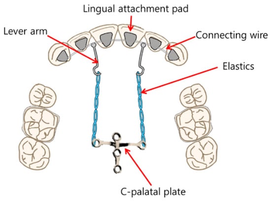
Figure 1.
Schematic representation of C-lingual retractor (CLR).
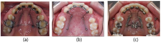
Figure 2.
Modifications of the C-lingual retractor (CLR): (a) lever arms positioned between both central and lateral incisors, and TPA between both first molars; (b) lever arms on both canines, and miniscrews on palatal slope; (c) lever arms positioned between both central and lateral incisor, and C-palatal plate.
3.2. Design of the DJR with TSADs
DJR comprises three main components: (1) a lingual attachment part, (2) an activating part, and (3) a mini-implant part [22].
The lingual connecting arch made of a 0.036-inch SS wire is soldered to the attachment pads and bonded to the lingual surfaces of the anterior teeth. The lingual arch is bent to extend the helical spring from the canine to the first molar area. To prevent anterior torque loss during retraction, helical torquing springs are positioned to contact the mini-implants on the posterior palatal slope or allow the application of intermaxillary elastics. The lever arms are fabricated close to the height of the estimated CR of the maxillary anterior teeth and soldered to the lingual connecting arch (Figure 3) [1,2].
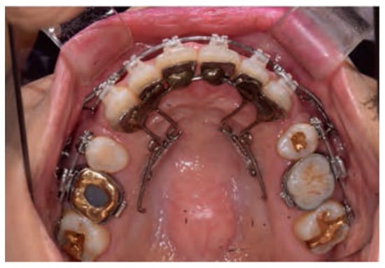
Figure 3.
Double J retractor (DJR).
In published journals, three different designs with varied helical torquing springs have been reported: (1) to activate the spring by contacting the mini-implant on the palatal slope (Figure 4); (2) to apply Class II elastics to the torquing spring on the palatal side (Figure 5); and (3) to apply elastics with extended spring to the buccal side (Figure 6).
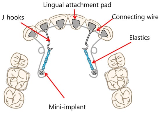
Figure 4.
Schematic representation of the Double J retractor (DJR) in which the torquing spring is activated by contacting the mini-implant on the palatal slope. Redrawn with permission from Am J Orthod Dentofacial Orthop [23].
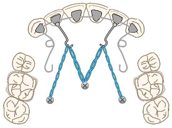
Figure 5.
Schematic representation of a Double J retractor (DJR) designed to apply Class II elastics to torquing springs on a palatal slope. Redrawn with permission from Am J Orthod Dentofacial Orthop [14].
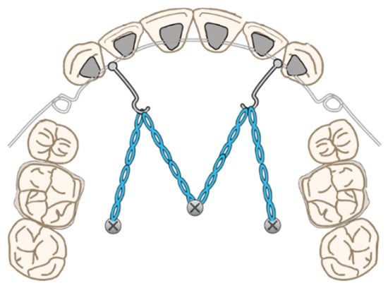
Figure 6.
Schematic representation of the Double J retractor (DJR) designed to apply Class II elastics to the extended spring to the buccal side. Redrawn with permission from Semin Orthod [22].
Jang et al. used the following design in a finite element analysis (Figure 4) [7]. The torquing spring was placed approximately 8 mm from the gingival line along the palatal mini-implant between the second premolar and first molar. Additionally, Liaw et al. reported a case using this design [23,31]. Park et al. [14] and Joo [22] reported designs made with elastics (Figure 5). In addition, DJR by Joo allows the application of elastics to the buccal side by extending the helical spring to the extraction space (Figure 6) [22]. The intermaxillary elastics for torque control support the helical torquing spring. A midpalatal mini-implant and two mini-implants on the palatal slopes of the first molars are used as anchors to retract the anterior teeth.
3.3. Design of the APLR with TSADs
The APLR basically consists of a C-lingual retractor bonded to the lingual surfaces of the six anterior teeth, lever arms, posterior splints, and posterior tubes, which act as pathways for the guide bar. The lever arms are soldered to the anterior splint, and the posterior tubes are soldered to the posterior splint. A guide bar with a diameter of 0.036-in extending from the lever arm passes and slides through the posterior tube (Figure 7) [1,5]. Friction in the APLR is minimized compared to conventional lingual brackets as the friction in the APLR occurs only between the guide bar and the posterior tube during retraction.
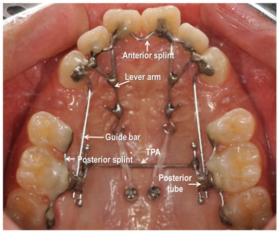
Figure 7.
Antero-posterior Lingual Retractor (APLR) appliance.
- (1)
- Anterior Segment
The anterior part of the APLR was similar to that of the CLR. In addition, the 0.036-in stainless steel guide bar, soldered to the lever arm or attachment pad extends posteriorly into the posterior tube [1,5].
- (2)
- Posterior Segments
The posterior connecting wire is soldered to the posterior attachment pad to be positioned on the second premolar, first and second molar to form a posterior splint. A posterior tube 1 mm in diameter, typically parallel to the occlusal plane is soldered to the first molar area of the posterior splint and acts as a sliding path. The guide bar soldered to the anterior segment passes through the posterior tube and the clearance between the guide bar and posterior tube is approximately 0.1 mm [1,5].
- (3)
- Accessory Parts
The transverse dimension is controlled by adding a TPA. It is soldered to the extended arm which is connected to the first molar pad. In some cases, additional hooks are added to the TPA for posterior intrusion or torque control [1].
- (4)
- TSADs
Generally, miniscrews or C-palatal plate are placed in the midpalatal area for torque and vertical control of anterior teeth [5].
4. Biomechanics of Various Lingual Retractors with TSADs
4.1. CR of Six Maxillary Anterior Teeth
The results of various studies on the CRs of six maxillary anterior teeth are as follows. In Lee et al.’s study, the vertical position of the CR during lingual retraction of six maxillary anterior teeth, it was located at a distance of 6.76mm and 44.32% from the CEJ toward the apical [32]. Jang et al. evaluated the CR of six maxillary anterior teeth is located 12.2 mm apical to the incisal edge of the central incisor [7]. Jeong et al. said that the CR of six maxillary anterior teeth was 13.5 mm apical and 14.0 mm posterior to the incisal edge of the central incisor [33].
4.2. Biomechanics of the CLR with TSADs
The lever arm and TSADs system for anterior torque and vertical control during retraction in conventional lingual orthodontic treatment introduced by Hong et al. can also be applied to treatment using a CLR (Figure 8) [1,6]. Mo et al. analyzed the factors that affect torque and vertical control during anterior retraction by using a C-retractor and a palatal miniplate [28], and Park et al. evaluated the mechanism of tooth movement in en-masse retraction of maxillary anterior teeth using a palatal appliance with TSADs and lever arms [26].
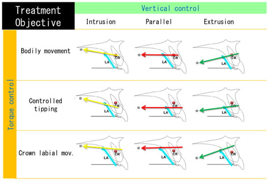
Figure 8.
Schematic diagram of the maxillary anterior movement pattern during anterior retraction according to the center of resistance (CR) position of the anterior teeth, the length of the lever arm and the height of the TSAD. Redrawn figure in Angle Orthod [6].
When the line of action of the force connecting the hook of the lever arm and TSADs passes through the CR of the anterior teeth, the maxillary anterior teeth are retracted with bodily movement. When it passes above the CR, the maxillary anterior teeth are retracted with lingual movement or root. However, when it passes below the CR, the maxillary anterior teeth are retracted with controlled tipping. Additionally, if the TSADs in the midpalatal area are positioned vertically above the hook of the lever arm, the maxillary anterior teeth are intruded. If the TSADs on the palatal slope are located at the same height as the hook of the lever arm, the maxillary anterior teeth are retracted in parallel, without vertical movement [1,6,26,28].
Moreover, Mo et al. reported that the effectiveness of torque control was improved when the lever arms were positioned between the central and lateral incisors compared to when they were placed between the lateral incisors and canines [28].
4.3. Biomechanics of the DJR with TSADs
Lingual lever arm mechanics is effective in controlling the anterior torque during retraction. Jang et al. evaluated the CR of six maxillary anterior teeth and found that it is located 12.2 mm apical to the incisal edge of the central incisor [7]. Therefore, they stated that during anterior retraction using DJR, the optimal position of the mini-implants should be 8 mm from the cervical level of the first molar [7]. Torquing springs are activated either directly by mini-implants or by applying intermaxillary elastics to counteract the lingual tipping movement of the anterior teeth during retraction (Figure 9) [23].
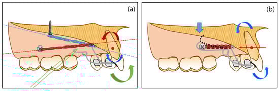
Figure 9.
Comparison of different force systems generated with different designs of double J Retractors (DJRs): (a) direction of force that passing above and below the center of resistance (CR) of the anterior teeth and application of intermaxillary elastics; (b) direction of the force that passes through the CR of the anterior teeth and activation of helical torquing spring. Redrawn with permission from Am J Orthod Dentofacial Orthop [22].
Figure 9a shows that the direction of the force passing above and below the CR of the anterior teeth is equal to the direction of force passing through the CR. Class II intermaxillary elastics generates the forward rotation moment of the anterior teeth [23,31]. Figure 9b shows the direction of force that passes through the CR of the anterior teeth, allowing bodily movement of the anterior teeth. During retraction, a downward force can be generated by contacting the mini-implants with a torquing spring. Therefore, it creates the forward rotation moment in the anterior teeth [23,31].
4.4. Biomechanics of the APLR with TSADs
APLR can adjust the three-dimensional control of anterior teeth with the anterior lever arm, guide bar, posterior tube, and position of TSADs. As shown in Figure 10, when force is applied from the lever arm to the TSADs in the midpalatal area, the anterior teeth are intruded and retracted with torque control. The posterior teeth are intruded by the kinetic energy generated when the force direction and the guide bar are not parallel. Resultantly, the mandible is autorotated counterclockwise, and the occlusal plane is maintained or flattened [34,35]. Therefore, APLR is effective when applied to hyperdivergent Class II patients with a gummy smile or uprighted maxillary incisors [1,5,24,34,35].
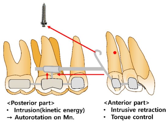
Figure 10.
Biomechanics of the antero-posterior lingual retractor (APLR).
Based on the combination of the length of the extended arms and the location of TSADs, the effective vertical movement of the anterior teeth is possible with adequate torque control [1,5,24]. A heavy guide bar connected to the posterior segments effectively controls the retraction vector to prevent anterior torque loss [34,35]. The posterior tube also controls the amount of intrusion of the anterior teeth. A previous study suggested that the angular change of the posterior tube of the APLR resulted in a difference in the intrusion amount of the anterior teeth [35]. If the angulation of the posterior tube was parallel to the maxillary occlusal plane, the anterior segment showed bodily movement without angulation change (Figure 11B) [34,35]. When the tube angulation was tipped disto-occlusally, the intrusion amount of the maxillary anterior teeth increased (Figure 11C). Therefore, the maxillary anterior teeth in patients with an excessive gingival display can be effectively controlled by changing the angulation of the tube [35].
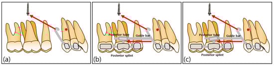
Figure 11.
Schematic diagrams of the C-lingual retractor (CLR) and antero-posterior lingual retractor (APLR): (a) CLR group; (b) APLR group with parallel posterior tubes; (c) APLR group with distally angulated posterior tube.
5. Treatment Results and Discussion
Kim et al. analyzed the treatment results of 35 patients who underwent maxillary anterior retraction by applying a CLR with a C-palatal plate [9]. In patients requiring bodily tooth movement (SN-U1 < 105°), a long lever arm approximately 10 mm from the facial axis point (FA point) of the lingual side of the six anterior teeth was applied. Conversely, in patients requiring controlled tipping (SN-U1 > 105°), a short lever arm approximately 7 mm from the FA point on the lingual side of the six maxillary anterior teeth was used. The lever arms of all patients were located between the central and lateral incisors [9,36]. In the long lever arm group, SN-U1 decreased by 7.8°, and in the short lever arm group, SN-U1 decreased by 12.0°. In both groups, the maxillary incisors were intruded by 1.1 mm. The authors concluded that reasonable torque control and effective intrusion of the anterior teeth were possible using CLR with TSADs [9].
To our knowledge, no study has analyzed the treatment results for improving anterior protrusion using DJR; therefore, all case reports related to DJR have been reviewed, including three Class II cases [14,30,34]. Liaw et al. reported two extraction cases in skeletal Class II patients with anterior protrusion using DJR [23,31]. In the first case, a DJR designed to allow a helical torquing spring to be activated directly on the mini-implant was fabricated by placing two miniscrews on the palatal slope [31]. The maxillary incisors were retracted 5.0 mm and intruded 2.8 mm, with adequate maxillary incisor torque control (SN-U1, from 102.58° to 103.88°), thus, effectively reducing the anterior protrusion [31]. In the second case, treatment results showed 7 mm retraction and 1.5 mm intrusion of maxillary incisors. The maxillary first molars were extruded by 1 mm [23]. Incisal torque control during space closure was adequate. Moreover, the maxillary incisors showed a retroclination of 4.1° (SN-U1, from 100.2° to 96.1°) [23]. These suggest generating torque-controlled retraction and intrusion force by activating the helical spring during anterior retraction. Furthermore, Park et al. reported a case of skeletal Class II patients with an anterior protrusion in which the helical spring was activated using elastics [14]. Only the maxillary first premolars were extracted, and bodily translation of the anterior teeth was planned using DJR. Class II elastics were applied to the palatal side of the helical spring and mandibular first molar to control maxillary incisal torque. To minimize the extrusive force, elastics were worn only at night. The upper incisal torque was well-controlled (SN to U1, from 96.2° to 90.7°). When reviewing the above three cases using DJR with TSADs [2,14,31], the torque loss of the maxillary incisors was smaller than that in cases using CLR with a C-palatal plate [9]. However, additional studies with larger sample sizes are needed to confirm these results.
Unlike CLR and DJR, APLR allows not only intrusion of the maxillary incisors but also intrusion of the maxillary molars. Therefore, APLR with TSADs is effective in hyperdivergent patients with lip protrusion, a gummy smile, or uprighted maxillary incisors [1,5,24]. In a case report by Park et al., a skeletal Class I patient with anterior protrusion was treated using APLR with TSADs. The maxillary incisors were retracted by 4.5 mm and intruded by 5 mm simultaneously without loss of anterior torque. Meanwhile, the maxillary molars also showed an intrusion by 2 mm without significant mesial movement resulting in a flattened occlusal plane [1]. The maxillary total arch intrusion resulted in rotation of the mandible, which induced comfortable lip closure and a favorable profile. Nahm et al. [13] also reported a case in which APLR with TSADs was applied in a skeletal Class II patient with a hyperdivergent pattern showing a gummy smile. As a result of treatment, bodily retraction and intrusion of the incisors, total intrusion of the maxillary dentition, and mandibular autorotation were achieved. The gummy smile was resolved by extensive anterior retraction and intrusion with proper torque control [13].
Kwon et al. reported two cases in which APLR was applied to a skeletal Class II patient with a hyperdivergent pattern, but autorotation occurred differently. In the first case, the maxillary incisors showed bodily retraction and intrusion, and the molars were intruded by 1.5 mm, which resulted in mandibular counterclockwise autorotation and the anterior positioning of Pogonion by 1.6 mm [5]. In the second case, the maxillary incisors showed controlled tipping, with intrusion by 4 mm and retraction by 7 mm. The maxillary molar intrusion was 1.5 mm. However, no autorotation was observed, contrary to other cases [5]. This may result from mandibular repositioning after resolving of the CO-CR discrepancy [5].
Next, considering the effect of APLR on periodontal tissue, despite the significant amount of retraction, the alveolar bone around the incisors did not show vertical bone loss [5]. APLR showed similar results to the conventional appliances for alveolar bone loss in the palate; however, significantly smaller vertical alveolar bone loss was found when APLR was used. This is because, regardless of the type of lingual retractor, the anterior teeth are splinted together [34,37,38].
Finally, there have been no reports on the long-term stability of APLR with TSADs. However, in a case report by Nahm et al., stable occlusion and periodontal health were shown after a retention period of one year [13]. The treatment stability using APLR is expected to deliver results similar to the long-term stability of intrusion and en-mass retraction. This necessitates future studies on the long-term stability of lingual retractors.
6. Future Perspectives
Kwon et al. showed that APLR (KILBON) can be designed using CAD/CAM soft-ware including 3Txer (ver. 2.5, Orapix, Seoul, Korea) and Rhinoceros 3D (ver 5.0, Rob-ert McNeel & Associates, Seattle, WA, USA) (Figure 12) [24]. Because 3D digital technology is rapidly developing, it is judged that these technologies will be applied to lingual retractors in various ways, and accordingly, lingual retractors are expected to become more popular.
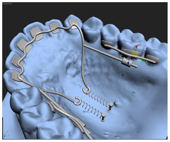
Figure 12.
Virtual design of antero-posterior lingual retractor with software program.
7. Conclusions
- -
- All lingual retractors can control the torque and vertical movement of maxillary incisors by changing the length of the lever arm and position of the TSADs.
- -
- In DJR, the torquing spring plays an additional role in anterior torque control.
- -
- In APLR, changes in the guide bar and posterior tube play an additional role in anterior torque and vertical control.
Author Contributions
Conceptualization, J.-Y.C., K.-A.K., J.L., Y.-S.L., K.-R.C. and K.-H.P.; Investigation, J.L. and Y.-S.L.; Methodology, J.-Y.C., K.-A.K., K.-R.C. and K.-H.P.; Project administration, J.-Y.C. and K.-A.K.; Supervision, K.-R.C. and K.-H.P.; Visualization, J.L. and Y.-S.L.; Writing—original draft, J.-Y.C., K.-A.K., J.L., Y.-S.L. and K.-H.P.; Writing—review & editing, K.-R.C. All authors have read and agreed to the published version of the manuscript.
Funding
This research received no external funding.
Institutional Review Board Statement
Not applicable.
Informed Consent Statement
Not applicable.
Data Availability Statement
Not applicable.
Conflicts of Interest
The authors declare no conflict of interest.
References
- Park, K.H.; Ahn, H.W.; Kang, Y.G. Chapter 50. TAD-assisted Lingual Retractors. In Temporary Anchorage Devices in Clinical Orthodontics; Park, J.H., Ed.; Wiley Blackwell: Hoboken, NJ, USA, 2020; pp. 527–540. [Google Scholar]
- Chung, K.R.; Kook, Y.A.; Kim, S.H.; Mo, S.S.; Jung, J.A. Class II malocclusion treated by combining a lingual retractor and a palatal plate. Am. J. Orthod. Dentofacial. Orthop. 2008, 133, 112–123. [Google Scholar] [CrossRef] [PubMed]
- Chung, K.R.; Kim, S.H.; Lee, B.S. Speedy surgical-orthodontic treatment with temporary anchorage devices as an alternative to orthognathic surgery. Am. J. Orthod. Dentofacial. Orthop. 2009, 135, 787–798. [Google Scholar] [CrossRef] [PubMed]
- Park, Y.C.; Choi, Y.J.; Choi, N.C.; Lee, J.S. Esthetic segmental retraction of maxillary anterior teeth with a palatal appliance and orthodontic mini-implants. Am. J. Orthod. Dentofacial. Orthop. 2007, 1, 537–544. [Google Scholar] [CrossRef] [PubMed]
- Kwon, S.Y.; Ahn, H.W.; Kim, S.H.; Park, Y.G.; Chung, K.R.; Paik, C.H.; Nelson, G. Antero-posterior lingual sliding retraction system for orthodontic correction of hyperdivergent Class II protrusion. Head Face Med. 2014, 10, 22. [Google Scholar] [CrossRef] [PubMed]
- Hong, R.K.; Heo, J.M.; Ha, Y.K. Lever-arm and mini-implant system for anterior torque control during retraction in lingual orthodontic treatment. Angle Orthod. 2005, 75, 129–141. [Google Scholar]
- Jang, H.J.; Roh, W.J.; Joo, B.H.; Park, K.H.; Kim, S.J.; Park, Y.G. Locating the center of resistance of maxillary anterior teeth retracted by Double J Retractor with palatal miniscrews. Angle Orthod. 2010, 80, 1023–1028. [Google Scholar] [CrossRef]
- Sung, S.J.; Jang, G.W.; Chun, Y.S.; Moon, Y.S. Effective en-masse retraction design with orthodontic mini-implant anchorage: A finite element analysis. Am. J. Orthod. Dentofacial. Orthop. 2010, 137, 648–657. [Google Scholar] [CrossRef]
- Kim, J.S.; Kim, S.H.; Kook, Y.A.; Chung, G.R.; Nelson, G. Analysis of lingual en masse retraction combining a C-lingual retractor and a palatal plate. Angle Orthod. 2011, 81, 662–669. [Google Scholar] [CrossRef]
- Chung, K.R.; Oh, M.Y.; Ko, S.J. Corticotomy-assisted orthodontics. J. Clin. Orthod. 2001, 35, 331–339. [Google Scholar]
- Kim, S.H.; Park, Y.G.; Chung, K.R. Severe anterior open bite malocclusion with multiple odontoma treated by C-lingual retractor and horseshoe mechanics. Angle Orthod. 2003, 73, 206–212. [Google Scholar]
- Kim, S.H.; Park, Y.G.; Chung, K.R. Severe Class II anterior deep bite malocclusion treated with a C-lingual retractor. Angle Orthod. 2004, 74, 280–285. [Google Scholar]
- Nahm, K.Y.; Shin, S.Y.; Ahn, H.W.; Kim, S.H.; Nelson, G. Gummy smile correction using lingual orthodontics and augmented corticotomy in extremely thin alveolar housing. J. Craniofac. Surg. 2017, 28, 599–603. [Google Scholar] [CrossRef]
- Park, J.H.; Tai, K.; Takagi, M.; Miyajima, K.; Kojima, Y.; Joo, B.H. Esthetic orthodontic treatment with a double J retractor and temporary anchorage devices. Am. J. Orthod. Dentofacial. Orthop. 2012, 141, 796–805. [Google Scholar] [CrossRef]
- Park, J.R.; Cho, H.J. Three-dimensional evaluation of interradicular spaces and cortical bone thickness for the placement and initial stability of microimplants in adults. Am. J. Orthod. Dentofacial. Orthop. 2009, 136, 314–315. [Google Scholar] [CrossRef]
- Kang, Y.G.; Kim, J.Y.; Nam, J.H. Control of maxillary dentition with 2 midpalatal orthodontic miniscrews. Am. J. Orthod. Dentofacial. Orthop. 2011, 140, 879–885. [Google Scholar] [CrossRef]
- Asscherickx, K.; Vannet, B.V.; Bottenberg, P.; Wehrbein, H.; Sabzevar, M.M. Clinical observations and success rates of palatal implants. Am. J. Orthod. Dentofacial. Orthop. 2010, 137, 114–122. [Google Scholar] [CrossRef]
- Chung, K.R. Lingual mechanotherapy by lingual bonded edgewise appliance. Kyung Hee Univ. Med. J. 1986, 2, 87–106. [Google Scholar]
- Fontanelle, A. Lingual orthodontics in adults. In Current Controversies in Orthodontics; Melsen, B., Ed.; Quintessence Publishing Co.: Chicago, IL, USA, 1991; pp. 227–246. [Google Scholar]
- Siatkowski, R.E. Lingual lever-arm technique for en masse translation in patients with generalized marginal bone loss. J. Clin. Orthod. 1999, 33, 700–704. [Google Scholar]
- Park, Y.C.; Choi, K.C.; Lee, J.S.; Kim, T.K. Lever-arm mechanics in lingual orthodontics. J. Clin. Orthod. 2000, 34, 601–605. [Google Scholar]
- Joo, B.H. A new treatment method to retract anterior teeth with the double J retractor system in Class III malocclusions. Semin. Orthod. 2011, 17, 149–167. [Google Scholar] [CrossRef]
- Liaw, J.; Tai, S.; Huang, G. En-masse retraction of maxillary anterior teeth with the Double J retractor and palatal miniscrews: A case report. Am. J. Orthod. Dentofacial. Orthop. 2022, 161, 592–601. [Google Scholar] [CrossRef] [PubMed]
- Kwon, S.Y.; Kim, Y.; Ahn, H.W.; Kim, K.B.; Chung, K.R.; Kim, S.H. Computer-aided designing and manufacturing of lingual fixed orthodontic appliance using 2D/3D registration software and rapid prototyping. Int. J. Dent. 2014, 2014, 164164. [Google Scholar] [CrossRef] [PubMed]
- Khattab, T.Z.; Hajeer, M.Y.; Farah, H. Evaluation of the C-lingual retractor and the conventional lingual orthodontic brackets in terms of speech performance and oral discomfort: A randomized controlled trial. Cureus 2022, 14, e23752. [Google Scholar] [CrossRef] [PubMed]
- Park, J.H.; Kook, Y.A.; Kojima, Y.; Yun, S.; Chae, J.M. Palatal en-masse retraction of segmented maxillary anterior teeth: A finite element study. Korean J. Orthod. 2019, 49, 188–193. [Google Scholar] [CrossRef] [PubMed]
- Kim, K.A.; Lee, B.S.; Akbulut, A.S.; Kim, S.H.; Nelson, G. Maxillary Corticotomies with Bone-to-Bone Retraction and Mandibular Segmental Osteotomy for Correcting an Anterior Double Protrusion. J. Craniofac. Surg. 2017, 28, 757–760. [Google Scholar] [CrossRef]
- Mo, S.S.; Kim, S.H.; Sung, S.J.; Chung, K.R.; Chun, Y.S.; Kook, Y.A.; Nelson, G. Torque control during lingual anterior retraction without posterior appliances. Korean J. Orthod. 2013, 43, 3–14. [Google Scholar] [CrossRef]
- Sadek, M.M.; Sabet, N.E.; Hassan, I.T. Type of tooth movement during en masse retraction of the maxillary anterior teeth using labial versus lingual biocreative therapy in adults: A randomized clinical trial. Korean J. Orthod. 2019, 49, 381–392. [Google Scholar] [CrossRef]
- Zakkar, M.; Farah, H. Evaluation of C-lingual retractor effects on anterior teeth using cone beam computed tomographic imaging. Int. J. Appl. Dent. Sci. 2020. 6, 452–457.
- Liaw, J.; Huang, G.; Tsai, F.F.; Wang, S.H.; Liao, W. Torque control of maxillary anterior teeth with the double J retractor and palatal miniscrews during en masse retraction: A case report. Angle Orthod. 2022, 92, 562–572. [Google Scholar] [CrossRef]
- Lee, H.K.; Chung, K.R. The vertical location of the center of resistance for maxillary six anterior teeth during retraction using three dimensional finite element analysis. Korean J. Orthod. 2001, 31, 425–438. [Google Scholar]
- Jeong, G.M.; Sung, S.J.; Lee, K.J.; Chun, Y.S.; Mo, S.S. Finiteelement investigation of the center of resistance of the maxillary dentition. Korean J. Orthod. 2009, 39, 83–94. [Google Scholar] [CrossRef]
- Min, H.; Ahn, H.W.; Kwon, S.Y.; Choi, J.H.; Kim, S.H.; Nelson, G. Control of anterior segment using an antero-posterior lingual sliding retraction system: A preliminary cone-beam CT study. Prog. Orthod. 2018, 19, 2. [Google Scholar]
- Seo, K.W.; Kwon, S.Y.; Kim, K.A.; Park, K.H.; Kim, S.H.; Ahn, H.W.; Nelson, G. Displacement pattern of the anterior segment using antero-posterior lingual retractor combined with a palatal plate. Korean J. Orthod. 2015, 45, 289–298. [Google Scholar] [CrossRef]
- Park, H.S.; Lee, S.K.; Kwon, O.W. Group distal movement of teeth using microscrew implant anchorage. Angle Orthod. 2005, 75, 602–609. [Google Scholar]
- Ahn, H.W.; Moon, S.C.; Baek, S.H. Morphometric evaluation of changes in the alveolar bone and roots of the maxillary anterior teeth before and after en masse retraction using cone-beam computed tomography. Angle Orthod. 2013, 83, 212–221. [Google Scholar] [CrossRef]
- Jee, J.H.; Ahn, H.W.; Seo, K.W.; Kim, S.H.; Kook, Y.A.; Chung, K.R.; Nelson, G. En-masse retraction with a preformed nickel-titanium and stainless steel archwire assembly and temporary skeletal anchorage devices without posterior bonding. Korean J. Orthod. 2014, 44, 236–245. [Google Scholar] [CrossRef][Green Version]


Publisher’s Note: MDPI stays neutral with regard to jurisdictional claims in published maps and institutional affiliations. |
© 2022 by the authors. Licensee MDPI, Basel, Switzerland. This article is an open access article distributed under the terms and conditions of the Creative Commons Attribution (CC BY) license (https://creativecommons.org/licenses/by/4.0/).