Article

Modelling of Failure Behaviour of 3D-Printed Composite Parts

by
Madhukar Somireddy
1,2,
Aleksander Czekanski
2,* and
Sundar V. Atre
1
1
Department of Mechanical Engineering, University of Louisville, Louisville, KY 40292, USA
2
Department of Mechanical Engineering, York University, Toronto, ON M3J 1P3, Canada
*
Author to whom correspondence should be addressed.
Appl. Sci. 2022, 12(21), 10724; https://doi.org/10.3390/app122110724
Submission received: 23 September 2022 / Revised: 18 October 2022 / Accepted: 20 October 2022 / Published: 23 October 2022
(This article belongs to the Special Issue Composite Structures - Modelling, Testing and Manufacturing)

Abstract

:
Failure in 3D-printed composite parts is complex due to anisotropic properties, which are mainly governed by printing parameters, printing strategy, and materials. Understanding the failure behaviour of materials is crucial for the design calculations of parts. Effective computational methodologies are yet not available for accurately capturing the failure behaviour of 3D-printed parts. Therefore, we proposed two different computational methodologies for modelling the failure behaviour of 3D-printed parts. 3D-printed parts subjected to uniaxial tensile loading were considered for modelling. In the first method, the computational model employed nonlinear properties of virgin material, and the model predicted higher values than the experimental results. This method provided idealistic nonlinear behaviour of 3D-printed parts. The difference in the results of experimental and computational is significant, especially in the case of 3D-printed composites. In the second method, the computational model utilized nonlinear material data from mechanical testing results and the model predicted accurate nonlinear behaviour of 3D-printed parts. This method provided realistic material behaviour of 3D-printed parts. Therefore, for effective design and analysis, it is suggested to use the latter computational methodology to capture the failure behaviour of 3D-printed parts accurately.

1. Introduction

Additive manufacturing (AM) technology, also known as 3D printing, usage is increasing for many engineering applications [1]. Material extrusion-based AM technology is rising in popularity for producing large-scale composite structures [2], and further, the technology is versatile and can even process metals [3]. However, this latest manufacturing technology has certain limitations and challenges while processing composite materials, including voids, weak bonding of reinforcements and matrix, process-oriented properties, and weak interfacial properties [4,5]. Furthermore, the material properties of the printed parts are not the same as those of virgin material, which is used for 3D printing and anisotropy is introduced in the properties [6]. Such variation in the properties of 3D-printed parts leads to complex failure behaviour, and further, it is crucial to understand design calculations. Therefore, our work is focused on developing an efficient computational methodology for accurately capturing the failure behaviour of 3D-printed composite parts.
Several experimental works have focused on investigating the performance of 3D-printed parts under different mechanical loadings and its relation to the factors associated with the 3D printing process. Investigation of 3D-printed parts revealed that the process parameters, such as printing direction and build orientation, significantly influenced impact behaviour [7] and compressive behaviour [8]. Further, printing conditions, such as the temperatures of the bed and extruder, influenced the fracture properties of 3D-printed composites [9]. The interfacial fracture toughness of bimaterial composites can be enhanced with increased extruder temperature, but the increase in bed temperature can negatively affect the toughness. It was found that the angle-ply printing strategy exhibited better toughness than that of the cross-ply. However, the fatigue behaviour of 3D-printed composites with an angle ply printing strategy showed early stiffness degradation compared to other printing strategies [10]. Anisotropic performance is typical in 3D-printed lattice structures due to the variation in printing direction [11]. Investigation [12], on the flexural behaviour of printed composite parts, revealed that the composite material’s distribution of reinforcements significantly influenced the parts’ flexural response. The printed parts exhibited linear and nonlinear behaviour before fracture. The above studies indicated that the material behaviour of the printed parts is significantly influenced by the printing conditions, process parameters, printing strategies, and materials.
Failure behaviour in 3D-printed parts is complex and is not a much-explored research topic. Understanding the failure of materials is important for the effective design of parts. Therefore, assessing the failure behaviour of the printed parts subjected to different mechanical loadings is gaining interest in recent times. Bouaziz et al. [13] employed fracture mechanics techniques, such as J integral and crack tip methods, to quantify the crack initiation and propagation in 3D-printed parts. Pan et al. [14] utilized acoustic emission technology to investigate the damage behaviour. The investigation revealed that matrix buckling and interface failure are the primary failure modes in 3D-printed composite parts subjected to flexural loading. Furthermore, microscopic examination using a micro-CT scanner revealed that the parts also have other damage modes, such as matrix buckling, debonding, delamination, and fibre breakage. On the other hand, the predominant failure modes in 3D-printed honeycomb sandwich structures are indentation, bending of face sheet and core, and core shear [15]. It is clear that different failure modes occur in 3D-printed parts, and no single failure mode is primarily responsible for the ultimate failure of parts. Investigation on 3D-printed parts revealed that they have directional properties as well as the material behaviour of the parts is similar to that of laminate composites [16]. Therefore, the mechanics of laminates and laminate theories were proposed for characterizing the mechanical behaviour of 3D-printed parts. Typically, classical first-ply failure criteria were used to assess the laminates’ strength. However, strength and safety-oriented failure criteria for design are a more difficult proposition. An alternative to assessing the structural performance of the printed parts is computational modelling.
Computational methods [17], such as the finite element (FE) method, are the alternate solutions to experimental work, and further, these computational methods eliminate the challenges associated with experimental work. Scapin et al. [18] conducted an FE analysis to investigate the structural performance of printed parts with different infill patterns. The investigations [19] revealed that the material behaviour of the parts is transversely isotropic. The influence of printing parameters on the elastic response of 3D printed arc structures was investigated using FE analysis [20] and found that overlap between the layers significantly influenced the performance of structures. Cerda-Avila et al. [21] proposed alternate analytical methods for the preliminary design and analysis of 3D-printed parts subjected to uniaxial loading. The vibrational characteristics of 3D-printed parts were assessed using the finite element method [22]. A new computational tool was developed to accurately capture the intricate details of microstructure, which is important in the computational material modelling of 3D-printed parts [23]. The above studies only focused on investigating the macro-level structural performance of 3D-printed parts subjected to different loading conditions and did not consider intricate details of microstructure, which primarily governs the final material behaviour of 3D-printed parts. Computational models based on micromechanical approach considers the microstructure of parts and are useful for determining the material properties and investigating the failure behaviour of 3D-printed parts.
Micromechanical computational models employ microstructure, which is built during 3D printing, and the intricate details of microstructure are represented in representative volume element (RVE) or unit-cell for material modelling to estimate the properties. Recently, Dialami et al. [24] developed a computational model based on the homogenization technique for investigating the influence of printing strategies on the properties of 3D-printed structures. Furthermore, the influence of change in microstructure in different sections of 3D-printed parts on the mechanical performance was assessed experimentally and computationally [25]. Several studies employed the computational homogenization method to predict the properties of the printed parts: for PLA material [26], for nanocomposite material [27], for different mechanical loadings [28], and for different printing strategies [29]. Sayyidmousavi et al. [30] developed a computationally efficient micromechanical model based on a unit-cell model to predict the properties of 3D-printed composites. Analytical homogenization was proposed to predict the influence of process parameters on the deformation of 3D-printed parts [31]. Monaldo et al. [32] developed a multiscale approach based on the nonlinear homogenization method and elastoplastic constitutive law to determine the material behaviour of 3D-printed parts under mechanical loadings. In another study, Wei et al. [33] applied an elastic-plastic homogenization model along with the von Mises failure criterion for investigating the material behaviour of 3D-printed parts. In composite materials, bonding between the fibre and matrix is critical for determining the material behaviour, and this interface is modelled with cohesive-zone modelling in RVEs of 3D-printed parts [34]. Intricate details of microstructure are crucial in computational models; thus, this novel mathematical model based on the volume-conserving model was proposed for investigating the dimensional quality of 3D-printed parts [35]. Hasanov et al. [36] proposed a numerical homogenization method to investigate 3D-printed functionally graded material with different printing strategies. The results based on the simulations agreed with the experimental results. Recently, authors [37] revealed that 3D-printed parts have inferior quality, and thus, lead to a significant difference in the results of computational and experimental work. Most of the above computational work is limited to only elastic (linear) modelling. Further, a more realistic approach to predict accurate failure behaviour is crucial for the design calculations since the printing strategy governs the microstructure of the parts. Moreover, experimental work is expensive and tedious, and it fails to provide deeper insights into the failure at the microstructure level of 3D-printed parts. Therefore, computational modelling is needed to capture the failure behaviour of the parts. The topic is not yet much explored for the printed parts and is addressed in this work.
In this work, we considered 3D-printed parts via material extrusion additive manufacturing (ME-AM) for computational damage modelling. In the computational models, we considered the representative volume element for material modelling. Initially, linear material modelling is done based on the homogenization technique to determine the linear material properties, as discussed in the authors’ previous work [38], and then followed the nonlinear material modelling for capturing the damage behaviour of 3D-printed parts. Two different computational methodologies are proposed for damage modelling: one is based on utilizing nonlinear material properties of polymeric material, and the other is based on utilizing mechanical testing data of unidirectionally 3D-printed parts. Then, the computational damage models are implemented for investigating the failure behaviour of 3D-printed composite parts subjected to uniaxial tensile loading.

2. Materials and Methods

2.1. Materials

The 3D-printed parts can be considered laminate structures since their behaviour is similar to that of traditional laminates [16]. Laminate behaviour in 3D-printed parts is mainly contributed by two factors: printing direction (raster angle) and materials used in 3D printing. Therefore, in this work, we investigated the effects of variation in the printing direction and materials on the nonlinear behaviour of the printed parts during failure.
We considered two different commercially available filament materials for failure modelling of 3D-printed parts; the first one is a pure Acrylonitrile butadiene styrene (ABS) polymer, an isotropic material. The second material is a composite material that comprises 20% short Carbon fibres (sCF) in the ABS matrix; the materials data is available in [6,16]. Further, two printing strategies were considered (See Table 1), one resembles the cross-ply lay-up architecture, and the other is the angle-ply lay-up architecture in 3D-printed parts. In cross-ply lay-up architecture, the printing direction is 0° and 90° in the subsequent layers, and in angle-ply architecture, the printing direction is 45° and −45° in subsequent layers. 3D-printed parts considered in this work are shown in Figure 1. The printing direction, which is a raster angle, indicates the orientation of deposited material in each layer with respect to the length of the part. In our damage modelling, tensile loading is applied along the length of 3D-printed tensile coupons, which means that the raster angle is with respect to the loading direction. The above two printing strategies produce bidirectionally parts, which means that the subsequent layers in 3D-printed parts have different printing directions. On the other hand, unidirectionally 3D-printed parts have the same printing direction for all layers, for example, 0° raster angle for all layers.
The 3D-printed parts’ behaviour of the aforementioned materials and printing strategies was assessed experimentally in the works [6,16]. Experimental data of unidirectionally 3D-printed parts are adopted in one of the computational models of the present work, and more details are discussed in the following section. Furthermore, experimental work on bidirectionally 3D-printed parts is utilized for validating the results obtained from the present computational damage modelling. The bidirectionally 3D-printed parts with printing strategies [0°/90°]2S and [45°/−45°]2S are discussed in the damage modelling.

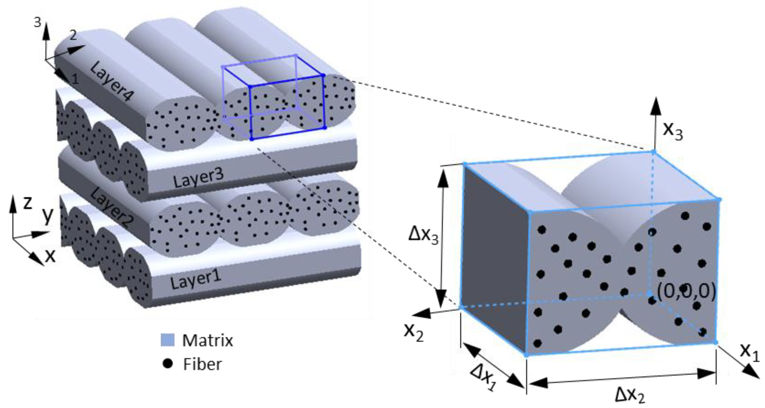
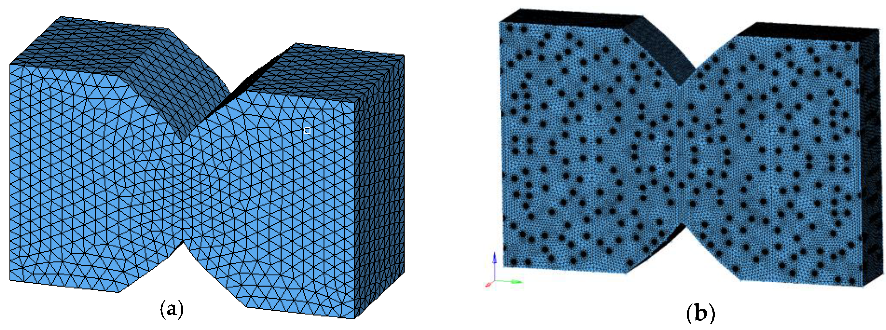
2.2. Computational Modelling

In this work, we applied numerical homogenization techniques for linear material modelling and for nonlinear material modelling. Computational models for modelling linear material behaviour were recently developed by authors [38]. In the present work, we focused on developing the computational procedure for nonlinear material modelling of the printed parts. A multiscale designer tool by Altair Engineering Inc is utilized for computational modelling. In this work, two different computational methodologies are developed for damage modelling.
In the computational modelling of linear material behaviour of 3D-printed parts, a unit cell is taken from the single layers’ microstructure of the printed parts. The unit cell is also referred to as the representative volume element (RVE), and is shown in Figure 2 for a composite 3D part. The layers of printed parts are considered as orthotropic and therefore, the RVE is treated as an orthotropic material. The stress–strain relationship for an orthotropic material is
[ C 11 C 12 C 13 0 0 0 C 12 C 22 C 23 0 0 0 C 13 C 23 C 33 0 0 0 0 0 0 C 44 0 0 0 0 0 0 C 55 0 0 0 0 0 0 C 66 ] { ε 11 ε 22 ε 33 γ 23 γ 13 γ 12 } ;   or   { σ } = [ C ] { ε }
where C is a constitutive matrix. The compliance matrix (S) is obtained by inverting the above equation.
{ ε 11 ε 22 ε 33 γ 23 γ 13 γ 12 } = [ S 11 S 12 S 13 0 0 0 S 12 S 22 S 23 0 0 0 S 13 S 23 S 33 0 0 0 0 0 0 S 44 0 0 0 0 0 0 S 55 0 0 0 0 0 0 S 66 ] { σ 11 σ 22 σ 33 τ 23 τ 13 τ 12 } ;   or   { ε } = [ S ] { σ }
the coefficients S matrix are
S 11 = 1 E 1 ,   S 12 = ν 12 E 1 , S 13 = ν 13 E 1 , S 22 = 1 E 2 , S 23 = ν 23 E 2 , S 33 = 1 E 3 , S 44 = 1 G 23 , S 55 = 1 G 13 , S 66 = 1 G 12
The RVE is considered macroscopically homogeneous in the homogenization technique, and the average stresses σ ¯ i j and average strains ε ¯ i j are calculated using the following equations
σ ¯ i j = 1 V RVE V σ i j ( x 1 , x 2 , x 3 ) d V ,   ε ¯ i j = 1 V RVE V ε i j ( x 1 , x 2 , x 3 ) d V
The average stress and strain fields for fibre and matrix in an RVE are written as
ε ¯ i j = v f ε ¯ i j f + v m ε ¯ i j m
σ ¯ = v f σ ¯ i j f + v m σ ¯ i j m
where f denotes fibre, and m denotes matrix material, respectively. The elastic constitutive relation for homogenized RVE is given as
{ σ ¯ } = [ C ] { ε ¯ }
From Equation (7) the constitutive matrix C is calculated by following the procedure as described in [39]. The finite element models of RVE are developed in order to apply a numerical homogenization method for determining the coefficients of effective stiffness matrix C for the layers of 3D-printed parts. More details on the computational models for linear material modelling are provided in [39]. Similar RVE models are developed in the present work for computational modelling of nonlinear behaviour of the parts.
Experimental investigations [6] revealed two types of macro failures in 3D-printed parts; these are breakages of extrudates and the debonding between adjacent extrudates. As well as the above two failure modes, fibre pullout is also observed in the case of composite 3D-printed parts [16]. Experimental work also revealed that the failure in 3D-printed parts is not brittle, but the printed parts experienced both linear and nonlinear behaviour which are seen in the stress–strain graphs of bidirectionally 3D-printed parts. Furthermore, experimental works uncovered that the polymeric material mainly contributes to the nonlinear behaviour in the parts, although the material used in the 3D printing is composite. It was also observed that the fibre reinforcements in the composites do not undergo deformation. Therefore, only ABS polymer’s nonlinear material behaviour is considered in the present work on damage modelling of 3D-printed parts. Further, the fibre reinforcement material is treated to remain elastic during the deformation. The following computational methodologies are developed for nonlinear material modelling of 3D-printed parts.

2.2.1. Computational Methodology-1

In the first computational methodology (CM-1), nonlinear properties of ABS polymer from Table 2 are employed for modelling. This method is based on isotropic damage and plasticity law. The finite element models of RVE are developed for this computational method. The finite element RVE models of 3D-printed parts for this computational method are shown in Figure 3. In these finite element models of RVE, the bonding at the interface of extrudates is assumed to be perfect. Furthermore, FE models of RVE of printed composite material have the following additional assumptions: perfect bonding between fibres and matrix, fibres are perfectly in line with the direction of the extrudate, and sCF reinforcements are positioned sparsely. These assumptions in the RVE FE models make the computational model idealistic. Material properties for ABS polymer from Table 2 and for Carbon fibre reinforcements from Table 3 are employed in the computational models.
Where the nonlinear material parameters in Table 2 represent σ Y -yield strength, σ U -ultimate strength, δ -exponent for the damage evolution law, H-linear term for hardening law, ε p 0 -equivalent plastic strain at which damage begins, ε p 1 -equivalent plastic strain at which damage causes zero stress, σ m e a n -mean stress at damage initiation, J1-volumetric strain to failure. More details about the damage law are available in the manual of the Multiscale designer tool by Altair [40]. The values of nonlinear parameters are obtained from the tensile testing data of ABS polymer, which is used for 3D printing.
This computational method is based on isotropic damage and plasticity law, which is commonly used for the damage modelling of polymers. Computational modelling for 3D-printed parts involves the following sequence of steps; firstly, linear material modelling using the homogenization technique for estimating linear material properties. Then, nonlinear material modelling uses the damage criterion and damage progression law to predict the failure of parts.

2.2.2. Computational Methodology-2

In the second computational method (CM-2), the tensile testing data of 3D-printed test coupons are utilized for modelling. The tensile test data of unidirectionally 3D-printed parts are shown in Figure 4. The FE models of RVEs for this computational method are shown in Figure 5a for the parts made of ABS material and Figure 5b for 3D-printed parts made of ABS + sCF composite material.
The main differences between the previous computational method and this method are the FE modelling of RVEs and nonlinear material data. In this case, the FE models of RVE have a different material (red region) for the interface of extrudates, and this considers the debonding failure mode. For nonlinear material data, it employs tensile testing data of unidirectionally 3D-printed parts (with 0° printing direction) for extrudates and the test data of printed parts (with 90° printing direction) for the interface material. The tensile testing data is considered to account for the predominant failure modes, debonding and breakage of extrudates in 3D-printed parts. 3D-printed parts with 0° printing direction experienced only breakage of extrudates, and in the case of the parts with 90° printing direction, they experienced only debonding at the interface of extrudates. The tensile test data of the above two cases can capture the actual failure behaviour of 3D-printed parts. The tensile testing data of unidirectionally 3D-printed parts from Figure 4a is utilized for computational modelling of the parts made of ABS polymer, and Figure 4b for modelling the parts made of composite material. Furthermore, implementing actual test data in the computational models eliminates several assumptions made in the previous case, including imperfect bonding at the interface and no pores within extrudates. This procedure makes the computational model realistic. Further, the method allows for the prediction of the nonlinear behaviour of 3D-printed parts accurately.

3. Results and Discussion

The material behaviour of 3D-printed parts subjected to tensile loading is characterized using two computational methodologies (CM-1 and CM-2) described in the previous section. Further, the computational models are applied for investigating the nonlinear material behaviour of 3D-printed parts made of two different materials (ABS and ABS + sCF) and with two different printing strategies: cross-ply and angle-ply.

3.1. Isotropic Material (ABS Polymer)

In this section, 3D-printed parts with ABS polymer are considered. The developed computational models are applied for damage modelling four different test coupons subjected to uniaxial tensile loading. The stress–strain curves are obtained using the present computational models and are then compared with existing experimental work.
The simulation results based on the computations models of CM-1 and CM-2 are in good agreement with the stress–strain curves of experimental work. Figure 6 shows the comparison of results for the printed parts with cross-ply and angle-ply printing strategies. The results obtained from the computational model of CM-1 are higher than those of other computational models and experimental work [6]. However, the stress–strain curve obtained from the results of CM-2 is comparable with the experimental results. The above discrepancy in the computational models is due to the CM-1 utilizing the virgin material properties for damage modelling. In contrast, the CM-2 utilizes testing data of 3D-printed parts for modelling nonlinear behaviour. Further, the difference in the experimental and computational models is due to the assumptions made in the finite element models.
Further, the results of the present computational models are compared with Tsai–Hill ply-based failure theory. For this, we calculated Ut-strength, Ex-stiffness along the x-axis, and εt-strain to failure from the results of computational models. Then, these properties are then compared with both experimental work and Tsai–Hill ply failure theory in Table 4. The Tsai–Hill failure criterion predicted lower stiffness and strength for 3D-printed parts. This difference in the results is due that the failure criterion employing the properties that were obtained from the mechanical testing results of uniaxially 3D-printed test coupons. The present computational models estimated higher results because of the assumptions in the FE models. However, the computational model based on CM-2 predicted accurate values because the nonlinear data for this is obtained from the mechanical testing data of uniaxially 3D-printed test coupons. The difference between the computational results of the two printing strategies (cross-ply, angle-ply) is not significant, but from the experimental work, it is observed that the angle-ply 3D-printed parts sustained higher strain before undergoing a complete fracture when compared to the cross-ply 3D-printed parts.

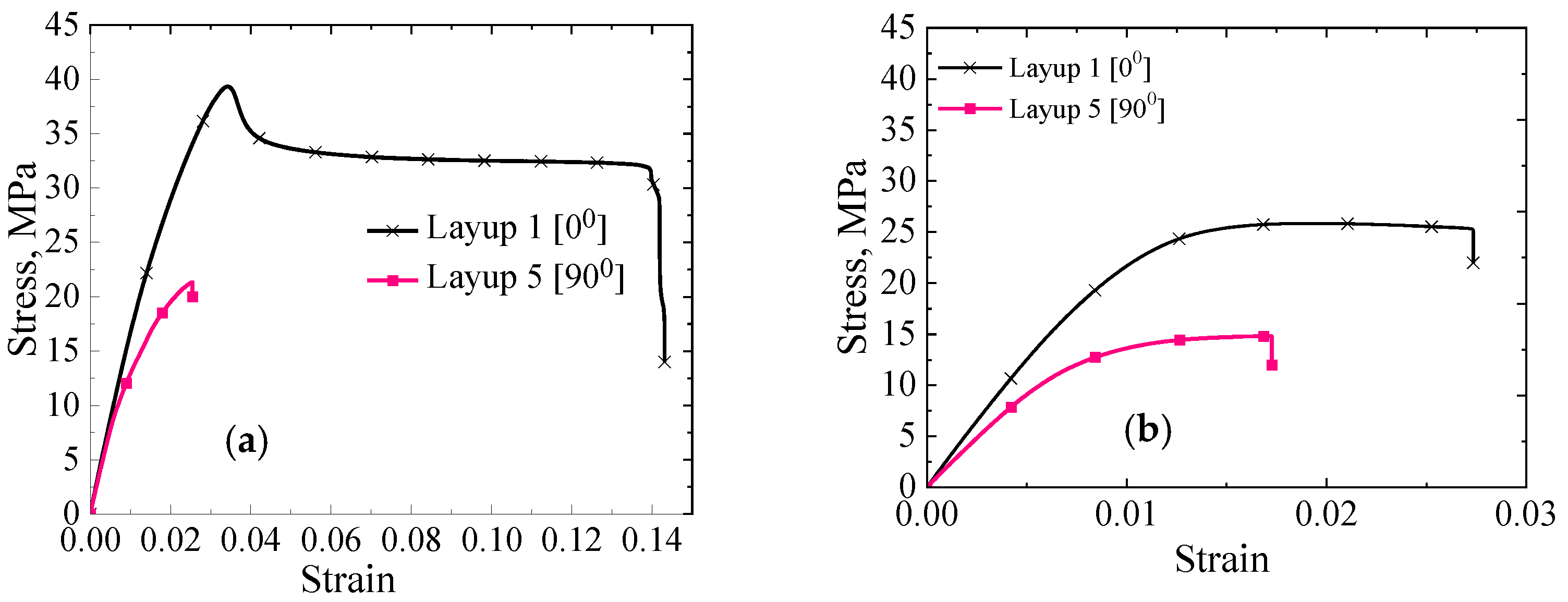
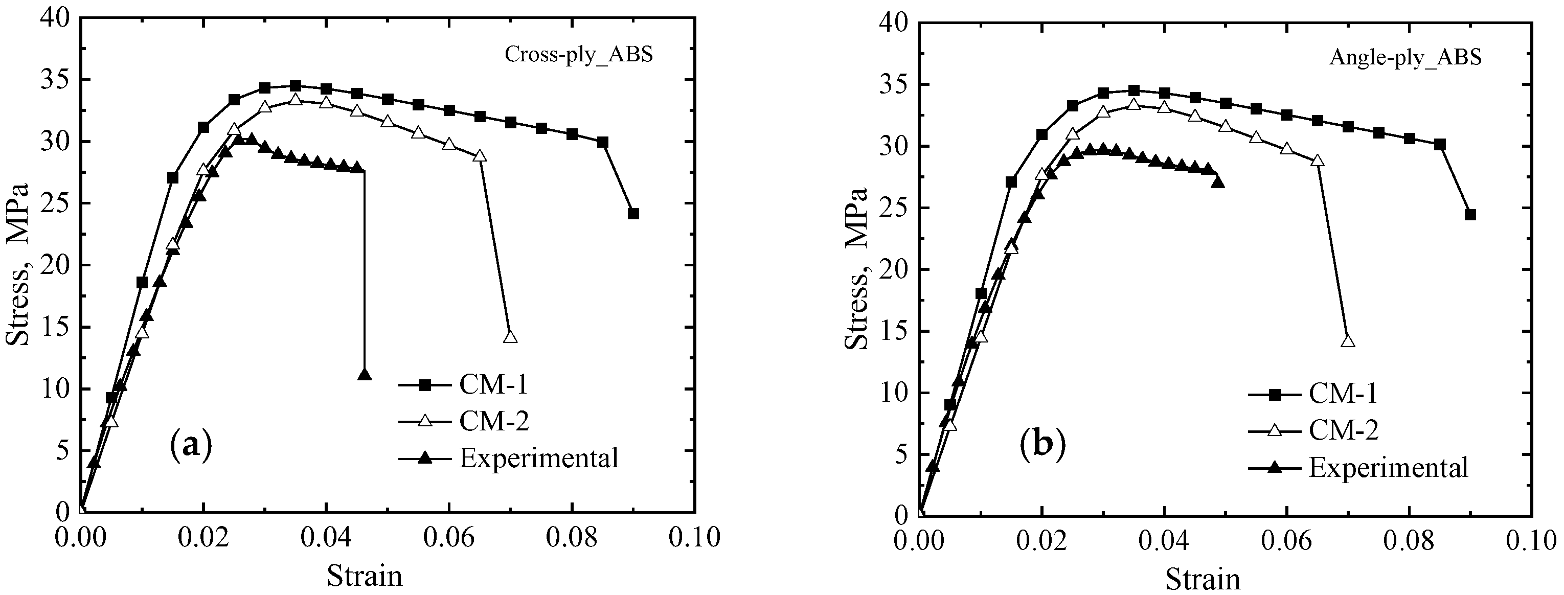
3.2. Composite Material (ABS + sCF)

In this section, we considered 3D-printed parts made of composite material for characterizing the nonlinear behaviour using computational models. The computational models are applied for four different test coupons as described in the previous section.
Experimental work on 3D-printed test coupons revealed that the nonlinearity during the deformation of the printed composites is attributed to only the ABS polymer. Therefore, the nonlinear behaviour of ABS materials alone is accounted for in the modelling of the 3D-printed composites. In contrast, the sCF reinforcements material’s behaviour remains linear while the printed composites are subjected to deformation. Finite element model preparation of RVE for 3D-printed composites was followed as explained in this work [37]. The results of the present computational models of CM-1 and CM-2 are compared with the stress–strain curves of experimental work [16]. The comparisons of results are presented in Figure 7a for cross-ply 3D-printed parts and Figure 7b for angle-ply 3D-printed parts.
Comparing the results of computational models with the results of experimental work reveals that the computational model based on CM-1 predicted higher values. However, the computational model based on CM-2 predicted accurate damage behaviour, and this is because this model employed actual mechanical testing data as described earlier. The difference between experimental and computational models of CM-1 is significant, mainly due to the process of inherited defects such as voids and misalignment of reinforcements’ orientation in the printed parts is not accounted for in the FE modelling of RVEs.
It is important to note from the stress–strain curves of 3D-printed3D-printed composites that during deformation, the printed parts initially follow linear behaviour and then exhibited hardening behaviour, and then the parts fail suddenly. On the contrary, 3D-printed ABS material has seen softening behaviour before the fracture. The hardening material behaviour in 3D-printed composites is mainly because of the presence of sCF reinforcements. Further, nonlinearity behaviour starts when the strength of the bonding between the ABS matrix and the sCF starts degrading during the deformation. After the hardening behaviour, the parts undergo sudden failure. This is due to the formation of larger discontinuity in the material and is caused by the coalescence of enclosed voids in the printed composites. This failure behaviour in the printed composites can be replicated in the computational models by considering mechanical testing data of the materials. The computational model, CM-2, that considered the mechanical testing results of the unidirectionally 3D-printed parts predicted the actual nonlinear behaviour of the parts.
Further, the present computational result is also compared with Tsai–Hill ply-based failure theory and existing experimental work. For this, we calculated material properties Ex, Ut, and εt from the simulation results. A comparison of the results is provided in Table 5 for cross-ply as well as angle-ply 3D-printed composite structures. The difference between experimental and computational results is up to 50% for properties, such as strength and strain to failure. The stiffness and strength of parts with the cross-ply printing strategy were higher than that of parts with the angle-ply printing strategy, but the angle-ply printed structures sustained higher strain to failure.

4. Conclusions

In this research work, we proposed two different computational methodologies for the failure modelling of 3D-printed parts. The computational models were then applied to investigate the nonlinear behaviour of 3D-printed parts subjected to tensile loading. The computational models based on CM-1 predicted higher values, and it is because the models employed the nonlinear material data of virgin material for modelling nonlinear behaviour. These computational models provided idealistic material behaviour of the parts. The computational models based on CM-2 predicted accurate damage behaviour of the printed parts, and this is because the models utilized the tensile testing data of uniaxially 3D-printed parts for the modelling of nonlinear behaviour. Computational models based on CM-2 provided realistic behaviour of the printed parts. The computational models were applied for 3D-printed parts and subjected to tensile loadings, only, to demonstrate the efficacy of the present computational models, and the models can be further applied to different mechanical loading cases. The following points are concluded from the research work:
  • The significant difference in the computational and experimental results indicates that the 3D-printed parts have inferior quality, and such parts can be further improved with proper selection of printing conditions and printing strategies.
  • The material behaviour of 3D-printed parts with an ABS polymer displayed linear behaviour followed by nonlinear softening behaviour before fracture. In contrast, 3D-printed3D-printed composite parts exhibited linear behaviour followed by nonlinear hardening behaviour before the sudden fracture. The hardening behaviour is mainly attributed to sCF in the composite parts.
  • Nonlinear behaviour in 3D-printed3D-printed composites is mainly attributed to matrix material (ABS polymer). Therefore, nonlinear data of ABS materials are considered for damage modelling, and the sCF reinforcements remain elastic during deformation.
  • For realistic failure modelling of 3D-printed parts, it is recommended to use the mechanical testing data of unidirectionally 3D-printed parts in the computational models. Further, consider the mechanical testing data to replicate the predominant failure modes in the computational models.

Author Contributions

Formal analysis, M.S. and A.C.; Investigation, M.S. and S.V.A.; Methodology, A.C.; Resources, A.C.; Validation, M.S.; Writing—original draft, M.S.; Writing—review & editing, A.C. and S.V.A. All authors have read and agreed to the published version of the manuscript.

Funding

This research was funded by Natural Sciences and Engineering Research Council (NSERC) of Canada for the financial support (Reference number PDF-557243-2021).

Acknowledgments

M.S. would like to acknowledge the Natural Sciences and Engineering Research Council (NSERC) of Canada for the financial support (Reference number PDF-557243-2021).

Conflicts of Interest

The authors declare no conflict of interest.

References

  1. Pal, A.K.; Mohanty, A.K.; Misra, M. Additive manufacturing technology of polymeric materials for customized products: Recent developments and future prospective. RSC Adv. 2021, 11, 36398–36438. [Google Scholar] [CrossRef] [PubMed]
  2. Pignatelli, F.; Percoco, G. An application-and market-oriented review on large format additive manufacturing, focusing on polymer pellet-based 3D printing. Prog. Addit. Manuf. 2022. [Google Scholar] [CrossRef]
  3. Singh, P.; Balla, V.K.; Gokce, A.; Atre, S.V.; Kate, K.H. Additive manufacturing of Ti-6Al-4V alloy by metal fused filament fabrication (MF3): Producing parts comparable to that of metal injection molding. Prog. Addit. Manuf. 2021, 6, 593–606. [Google Scholar] [CrossRef]
  4. Wu, Y.; Wang, K.; Neto, V.; Peng, Y.; Valente, R.; Ahzi, S. Interfacial behaviors of continuous carbon fiber reinforced polymers manufactured by fused filament fabrication: A review and prospect. Int. J. Mater. Form. 2022, 15, 18. [Google Scholar] [CrossRef]
  5. Balla, V.K.; Kate, K.H.; Satyavolu, J.; Singh, P.; Tadimeti, J.G.D. Additive manufacturing of natural fiber reinforced polymer composites: Processing and prospects. Compos. Part B Eng. 2019, 174, 106956. [Google Scholar] [CrossRef]
  6. Somireddy, M.; Singh, C.V.; Czekanski, A. Analysis of the material behavior of 3D printed laminates via FFF. Exp. Mech. 2019, 59, 871–881. [Google Scholar] [CrossRef]
  7. Patterson, A.E.; Pereira, T.R.; Allison, J.T.; Messimer, S.L. IZOD impact properties of full-density fused deposition modeling polymer materials with respect to raster angle and print orientation. Proc. Inst. Mech. Eng. Part C J. Mech. Eng. Sci. 2021, 235, 1891–1908. [Google Scholar] [CrossRef]
  8. Dou, H.; Ye, W.; Zhang, D.; Cheng, Y.; Tian, Y. Compression performance with different build orientation of fused filament fabrication polylactic acid, acrylonitrile butadiene styrene, and polyether ether ketone. J. Mater. Eng. Perform. 2022, 31, 1925–1933. [Google Scholar] [CrossRef]
  9. Rabbi, M.F.; Chalivendra, V. Interfacial fracture characterization of multi-material additively manufactured polymer composites. Compos. Part C Open Access 2021, 5, 100145. [Google Scholar] [CrossRef]
  10. Gljušćić, M.; Franulović, M.; Lanc, D.; Božić, Ž. Application of digital image correlation in behavior modelling of AM CFRTP composites. Eng. Fail. Anal. 2022, 136, 106133. [Google Scholar] [CrossRef]
  11. Sun, Z.P.; Guo, Y.B.; Shim, V.P.W. Influence of printing direction on the dynamic response of additively-manufactured polymeric materials and lattices. Int. J. Impact Eng. 2022, 167, 104263. [Google Scholar] [CrossRef]
  12. Krzikalla, D.; Měsíček, J.; Halama, R.; Hajnyš, J.; Pagáč, M.; Čegan, T.; Petrů, J. On flexural properties of additive manufactured composites: Experimental, and numerical study. Compos. Sci. Technol. 2022, 218, 109182. [Google Scholar] [CrossRef]
  13. Bouaziz, M.A.; Marae-Djouda, J.; Zouaoui, M.; Gardan, J.; Hild, F. Crack growth measurement and J-integral evaluation of additively manufactured polymer using digital image correlation and FE modeling. Fatigue Fract. Eng. Mater. Struct. 2021, 44, 1318–1335. [Google Scholar] [CrossRef]
  14. Pan, Z.B.; Zhou, W.; Zhang, K.; Ma, L.H.; Liu, J. Flexural damage and failure behavior of 3D printed continuous fiber composites by complementary nondestructive testing technology. Polym. Compos. 2022, 43, 2864–2877. [Google Scholar] [CrossRef]
  15. Edelen III, D.L.; Bruck, H.A. Predicting failure modes of 3D-printed multi-material polymer sandwich structures from process parameters. J. Sandw. Struct. Mater. 2022, 24, 1049–1075. [Google Scholar] [CrossRef]
  16. Somireddy, M.; Singh, C.V.; Czekanski, A. Mechanical behaviour of 3D printed composite parts with short carbon fiber reinforcements. Eng. Fail. Anal. 2020, 107, 104232. [Google Scholar] [CrossRef]
  17. Prajapati, A.R.; Rajpurohit, S.R.; Somireddy, M. Computational Models: 3D Printing, Materials and Structures. In Fused Deposition Modeling Based 3D Printing; Springer: Cham, Switzerland, 2021; pp. 403–417. [Google Scholar]
  18. Scapin, M.; Peroni, L. Numerical simulations of components produced by fused deposition 3D printing. Materials 2021, 14, 4625. [Google Scholar] [CrossRef]
  19. Bonada, J.; Pastor, M.M.; Buj-Corral, I. Influence of Infill Pattern on the Elastic Mechanical Properties of Fused Filament Fabrication (FFF) Parts through Experimental Tests and Numerical Analyses. Materials 2021, 14, 5459. [Google Scholar] [CrossRef]
  20. Cuan-Urquizo, E.; Espinoza-Camacho, J.I.; Álvarez-Trejo, A.; Uribe, E.; Treviño-Quintanilla, C.D.; Crespo-Sánchez, S.E.; Gómez-Espinosa, A.; Roman-Flores, A.; Olvera-Silva, O. Elastic response of lattice arc structures fabricated using curved-layered fused deposition modeling. Mech. Adv. Mater. Struct. 2021, 28, 1498–1508. [Google Scholar] [CrossRef]
  21. Cerda-Avila, S.N.; Medellín-Castillo, H.I.; Lim, T. Analytical models to estimate the structural behaviour of fused deposition modelling components. Rapid Prototyp. J. 2021, 27, 658–670. [Google Scholar] [CrossRef]
  22. Yao, T.; Ouyang, H.; Dai, S.; Deng, Z.; Zhang, K. Effects of manufacturing micro-structure on vibration of FFF 3D printing plates: Material characterisation, numerical analysis and experimental study. Compos. Struct. 2021, 268, 113970. [Google Scholar] [CrossRef]
  23. Sosa-Rey, F.; Abderrafai, Y.; Lewis, A.D.; Therriault, D.; Piccirelli, N.; Lévesque, M. OpenFiberSeg: Open-source segmentation of individual fibers and porosity in tomographic scans of additively manufactured short fiber reinforced composites. Compos. Sci. Technol. 2022, 226, 109497. [Google Scholar] [CrossRef]
  24. Dialami, N.; Rivet, I.; Cervera, M.; Chiumenti, M. Computational characterization of polymeric materials 3D-printed via fused filament fabrication. Mech. Adv. Mater. Struct. 2022. [Google Scholar] [CrossRef]
  25. Rivet, I.; Dialami, N.; Cervera, M.; Chiumenti, M.; Reyes, G.; Pérez, M.A. Experimental, computational, and dimensional analysis of the mechanical performance of fused filament fabrication parts. Polymers 2021, 13, 1766. [Google Scholar] [CrossRef]
  26. Ferretti, P.; Santi, G.M.; Leon-Cardenas, C.; Fusari, E.; Donnici, G.; Frizziero, L. Representative Volume Element (RVE) Analysis for Mechanical Characterization of Fused Deposition Modeled Components. Polymers 2021, 13, 3555. [Google Scholar] [CrossRef]
  27. Moola, A.R.; Santo, J.; Penumakala, P.K. Multiscale analysis for predicting elastic properties of 3D printed polymer-graphene nanocomposites. Mater. Today Proc. 2022, 62, 4025–4029. [Google Scholar] [CrossRef]
  28. Gonabadi, H.; Chen, Y.; Yadav, A.; Bull, S. Investigation of the effect of raster angle, build orientation, and infill density on the elastic response of 3D printed parts using finite element microstructural modeling and homogenization techniques. Int. J. Adv. Manuf. Technol. 2022, 118, 1485–1510. [Google Scholar] [CrossRef]
  29. Sánchez-Balanzar, L.; Velázquez-Villegas, F.; Ruiz-Huerta, L.; Caballero-Ruiz, A. A multiscale analysis approach to predict mechanical properties in fused deposition modeling parts. Int. J. Adv. Manuf. Technol. 2021, 115, 2269–2279. [Google Scholar] [CrossRef]
  30. Sayyidmousavi, A.; Fawaz, Z. A micromechanical approach to the mechanical characterization of 3D-printed composites. Polym. Polym. Compos. 2022, 30, 09673911221078481. [Google Scholar] [CrossRef]
  31. Sharafi, S.; Santare, M.H.; Gerdes, J.; Advani, S.G. A multiscale modeling approach of the Fused Filament Fabrication process to predict the mechanical response of 3D printed parts. Addit. Manuf. 2022, 51, 102597. [Google Scholar] [CrossRef]
  32. Monaldo, E.; Marfia, S. Multiscale technique for the analysis of 3D-printed materials. Int. J. Solids Struct. 2021, 232, 111173. [Google Scholar] [CrossRef]
  33. Wei, N.; Yao, S.; Rao, Y.; Wang, K.; Peng, Y. An integrated prediction model for processing related yield strength of extrusion-based additive manufactured polymers. Mech. Adv. Mater. Struct. 2022. [Google Scholar] [CrossRef]
  34. Gljušćić, M.; Franulović, M.; Lanc, D.; Žerovnik, A. Representative volume element for microscale analysis of additively manufactured composites. Addit. Manuf. 2022, 56, 102902. [Google Scholar] [CrossRef]
  35. De Macedo, R.Q.; Ferreira, R.T.L.; Gleadall, A.; Ashcroft, I. VOLCO-X: Numerical simulation of material distribution and voids in extrusion additive manufacturing. Addit. Manuf. 2021, 40, 101900. [Google Scholar] [CrossRef]
  36. Hasanov, S.; Gupta, A.; Alifui-Segbaya, F.; Fidan, I. Hierarchical homogenization and experimental evaluation of functionally graded materials manufactured by the fused filament fabrication process. Compos. Struct. 2021, 275, 114488. [Google Scholar] [CrossRef]
  37. Tang, H.; Sun, Q.; Li, Z.; Su, X.; Yan, W. Longitudinal compression failure of 3D printed continuous carbon fiber reinforced composites: An experimental and computational study. Compos. Part A Appl. Sci. Manuf. 2021, 146, 106416. [Google Scholar] [CrossRef]
  38. Somireddy, M.; Czekanski, A. Computational modeling of constitutive behaviour of 3D printed composite structures. J. Mater. Res. Technol. 2021, 11, 1710–1718. [Google Scholar] [CrossRef]
  39. Somireddy, M. Multiscale Material Modeling of Additively Manufactured Composite Laminates. Ph.D. Thesis, York University, Toronto, ON, Canada, 2019. [Google Scholar]
  40. Multiscale Designer Tool; Altair Engineering Inc.: Troy, MI, USA; Available online: https://www.altair.com/multiscale-designer (accessed on 19 October 2022).
Figure 1. 3D-Printed parts for tensile testing (a) cross−ply (b) angle−ply printed laminates.
Applsci 12 10724 g001
Figure 2. Unit cell or representative volume element (RVE) of 3D-printed composite part [38].
Applsci 12 10724 g002
Figure 3. Finite element models of RVEs of 3D-printed parts for computational methodology-1 (CM-1): (a) ABS polymer, (b) ABS + sCF composite material.
Applsci 12 10724 g003
Figure 4. Tensile test data of uniaxially 3D-printed parts: (a) for ABS polymer [6], (b) ABS + sCF composite material [16].
Applsci 12 10724 g004
Figure 5. Finite element models of RVEs of 3D-printed parts for computational methodology-2 (CM-2) (a) ABS polymer, (b) ABS + sCF composite material.
Applsci 12 10724 g005
Figure 6. Stress–strain relation for 3D-printed parts made of ABS material for: (a) cross-ply and (b) angle-ply printing strategies.
Applsci 12 10724 g006
Figure 7. Stress–strain relation for 3D-printed parts made of ABS-SCF material for: (a) cross-ply and (b) angle-ply printing strategies.
Applsci 12 10724 g007
Table 1. Materials and printing strategies of 3D-printed parts.
Printing StrategyMaterials
ABS PolymerABS + sCF Composite
Cross-plyCross-ply_ABSCross-ply_ABS + sCF
Angle-plyAngle-ply_ABSAngle-ply_ABS + sCF
Table 2. Material properties of ABS polymer for nonlinear material modelling.
PropertyE,
in MPa
v σ Y
in MPa
σ U
in MPa
δ H ε p 0 ε p 1 σ m e a n J 1
Value22300.343040200−1000.070.10360.10
Table 3. Material properties of short Carbon fiber (sCF) reinforcements for damage modelling [38].
PropertyE1, in GPaE2, in GPaG12, in GPaG23, in GPaν12
Value225151570.02
Table 4. Comparison of computational results with the results of Tsai–Hill failure criterion and experimental work for 3D-printed parts made of ABS material and subjected to uniaxial tensile loading.
Experimental [6]CLT and Tsai–Hill [6]Computational Modelling
CM-1CM-2
Cross-ply
Ex, in MPa1783.9 ± 2.71673.01865.71751.1
Ut, in MPa29.7 ± 0.725.234.533.3
εt0.0367 ± 0.01350.01350.090.07
Angle-ply
Ex, in MPa1728.7 ± 16.41645.61810.21720.2
Ut, in MPa28.0 ± 1.325.535.433.8
εt0.0435 ± 0.00490.01430.090.069
Table 5. Comparison of computational results with Tsai–Hill failure criterion results and experimental work for 3D-printed parts made of ABS + sCF composite material and subjected to uniaxial tensile loading.
Experimental [16]CLT and Tsai–Hill [16]Computational Modelling
CM-1CM-2
Cross-ply
Ex, in MPa2863.9 ± 78.72125.93704.22974.5
Ut, in MPa23.5 ± 0.526.061.633.6
εt0.0158 ± 0.00060.00970.050.022
Angle-ply
Ex, in MPa2094.6 ± 43.51733.32594.02053.9
Ut, in MPa21.7 ± 0.522.743.5224.3
εt0.0243 ± 0.00110.01050.070.028
Publisher’s Note: MDPI stays neutral with regard to jurisdictional claims in published maps and institutional affiliations.

